25
8.4.
Disassembly Procedure for the
Lens
NOTE: When Disassembling and Assembling for the Lens
1. To minimize the possibility of the CCD being dirt, perform
disassemble and/or assemble under the condition of the
CCD is being mounted.
Disassembling procedures for the CCD unit, refer to item
8.6.
2. Take care that the dust and dirt are not entered into the
lens.
In case of the dust is putted on the lens, blow off them by
airbrush.
3. Do not touch the surface of lens.
4. Use lens cleaning KIT (BK)(VFK1900BK).
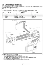
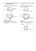
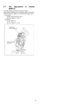
5. Apply the grease (VFK1829) to the point where is shown
to" Grease apply" in the figure.
When the grease is applied, use a toothpick and apply
thinly.
6. When repair the fixed frame, drive frame and direct
frame, must be unit exchange.
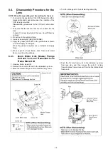
8.4.1.
Zoom Motor Unit, Master Frange
Unit and 1st Lens Frame/2nd Lens
Frame Move Unit
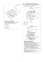
1. Unscrew the 4 screws (A).
2. Remove the zoom motor unit to the indicated by arrow.
3. Move the master frange unit to the indicated by arrow.
4. Turn the drive gear to the indicated by arrow fully.
5. Push the 1st lens frame unit to the indicated by arrow
from lens side, and then remove the unit of 1st lens
frame/2nd lens frame move unit from the fixed/drive/direct
frame unit.
Summary of Contents for Lumix DMC-FX33E
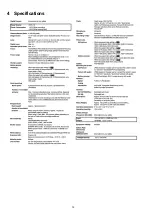
Page 12: ...12 4 Specifications ...
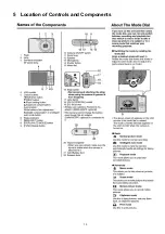
Page 13: ...13 5 Location of Controls and Components ...
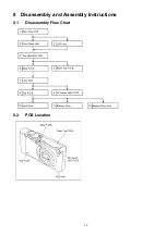
Page 19: ...19 8 Disassembly and Assembly Instructions 8 1 Disassembly Flow Chart 8 2 PCB Location ...
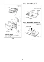
Page 21: ...21 Fig D2 8 3 2 Removal of the LCD Unit Fig D3 8 3 3 Removal of the Front Case Unit Fig D4 ...
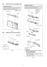
Page 23: ...23 Fig D8 8 3 6 Removal of the Main P C B Fig D9 8 3 7 Removal of the Lens Unit Fig D10 ...
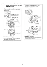
Page 28: ...28 8 5 4 Assembly for the Zoom Motor Unit Master Frange Unit and 2nd Lens Frame Move Unit ...

