63
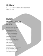
12.8. Hot Shoe Block Diagram
!!
& '
&# '
$!(
$!
$!!
!
$!!
$
$!!
2
$!!
#
&#'
&#'
&#'
&'
#
#
$!
(
$
%
()
()
()
()
()
&# '
$%!
& '
2(
2
2
2!
$!
$!(
$!
&# '
#
(
!
%
&# '
&# '
%
& ('
4
()
$!(
& '
(
2
$
%
%
%
%
(
%
(
(
(
!
$!
(
$
%
& '
%
& '
(
&# '
%$
& '
%2
&# #'
%2
&# #'
%
&# '
$%(
%%
()
(
%
B
!
2
$
$!
& '
(
%
B
!
2
$
$!
& '
Summary of Contents for Lumix DC-GH5SE
Page 16: ...16 ...
Page 17: ...17 ...
Page 18: ...18 ...
Page 19: ...19 ...
Page 26: ...26 ...
Page 27: ...27 ...
Page 30: ...30 ...
Page 34: ...34 9 1 2 P C B Location ...
Page 37: ...37 Fig D2 Fig D3 ...
Page 38: ...38 9 1 3 2 Removal of the Main P C B Fig D4 Fig D5 ...
Page 42: ...42 Fig D16 9 1 3 10 Removal of the Mount Box Unit Fig D17 Fig D18 ...
Page 46: ...46 9 1 3 18 Removal of the Rear Plate Unit Fig D26 Fig D27 ...
Page 48: ...48 Fig D30 9 1 3 21 Removal of the Strap Unit and EXT IF P C B Fig D31 ...
Page 49: ...49 Fig D32 9 1 3 22 Removal of the Image Sensor Unit Fig D33 ...
Page 63: ...63 12 8 Hot Shoe Block Diagram 2 2 2 2 2 4 2 2 2 B 2 B 2 ...
Page 64: ...64 12 9 Flash Syncro LTC Block Diagram F 2 2 4 2 2 2 2 ...
Page 66: ...66 12 11 Power 1 Block Diagram B 9 2 2 2 4 4 4 4 4 2 B 2 2 2 2 2 B 2 2 4 42 4 9 9 ...
Page 68: ...68 12 13 Power 3 Block Diagram 9 2 2 2 2 9 4 2 2 B B B B B B H 2 2 B B B B B B H 2 2 ...
Page 69: ...69 12 14 Power 4 Block Diagram 2 F B 2 2 F 2 B 2 4 2 2 2 B 2 B 2 ...