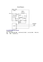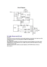
voltage appears at the Tip (T) and Ring (R) leads (When the telephone rings), the AC ring
voltage is transferred as follows:
T
L101
R2
C2
Q1
IC201 pin 27.
When the CPU (DSP) detects a ring signal, Q103 turns on, thus providing an off-hook condition
(active DC current flow through the circuit) and the following signal flow is for the voice signal.
T
D101
Q103
R119
C110
R117
R116
D103
D101
L102
P0S101
R.
ON HOOK Circuit:
Q103 is open, Q103 is connected as to cut the DC loop current and to cut the voice signal. The
unit is consequently in an on-hook condition.
SPECIFICATIONS
In the on-hook state (idle), the current flows between the telephone line and the unit is as
follows:
T
L101
R2
C2
R4
C3
R2
L102
R.
The DC component is blocked by C2, C3: thereby providing an on-hook condition.
The AC interface impedance is over 100k ; thus, satisfying the telephone company
requirements.
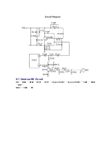
9.16. Initializing Circuit
Function:
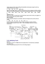
This circuit is used for to initialize the microcomputer when it incorporates an AC adaptor.
Circuit Operation:
The set can operate beyond point A in the circuit voltage diagram.
Summary of Contents for KX-TMC40JX-W
Page 3: ......
Page 7: ...4 2 Time and Date ...
Page 8: ......
Page 9: ...4 3 LCD Contrast ...
Page 10: ...4 4 Making Calls ...
Page 11: ......
Page 12: ...4 5 Answering Calls ...
Page 13: ...4 6 Caller ID Service ...
Page 14: ...4 7 Usin the Caller List ...
Page 15: ...4 8 Viewing the Caller List ...
Page 16: ...4 9 Calling Back from the Caller List ...
Page 18: ...4 12 FLASH Button ...
Page 40: ...10 CPU DATA 10 1 IC201 ...
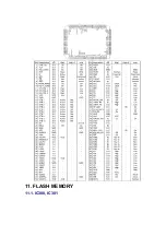
Page 41: ...11 FLASH MEMORY 11 1 IC300 IC301 ...
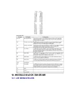
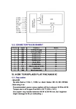
Page 42: ...12 MODULE BLOCK DIAGRAM 12 1 LCD MODULE BLOCK ...
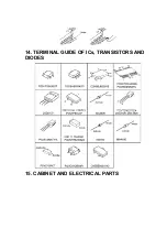
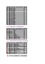
Page 45: ...14 TERMINAL GUIDE OF ICs TRANSISTORS AND DIODES 15 CABINET AND ELECTRICAL PARTS ...
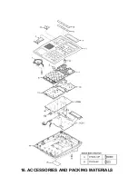
Page 46: ...16 ACCESSORIES AND PACKING MATERIALS ...
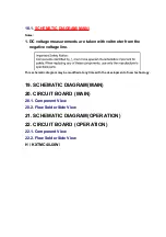
Page 62: ...CN801 MIC 2 1 24 23 PQUP11143ZA KX TMC40JXW OPERATION BOARD COMPONENT VIEW ...

