background image

19

KX-TG6323CPK/KX-TGA631CS

*R364

*R365

*C361

*R361

6.8u

*L361

6.8uH

*L371

K0.01

C305

120

R308

220

R304

220

R303

DCDC_IC

1

ON/*OFF

2

VSS

3

VOUT

5

VIN

4

EXT

22uH

L300

C304

K1.0

P101 22

10k

R113

100k

R141

*C132

K0.01

K0.01

C142

560

R175

1k

R178

47k

R114

390k

R121

390k

R122

1k

*R134

MIP

MIN

CHARGE-

C301

NC

NC

*R157

DCP2

DCM2

C111 0.047

C112 0.047

33u

L101

33u

L102

0.68

C113

C162

NC

C173

K0.22

C308

K0.1

NC

C179

NC

C174

D101

4

3

1

2

1M

*R133

1k

R154

100

R176

1

NC1

2

*RESET

3

VDET

4

VIN

5

VOUT

6

NC2

7

GND

8

CD

NC

C167

SA103

300V

*SA102

300V

10u

C176

*SA101

NC

2

1

35

47u

C300

0.022u

C178

NC

R371

NC

*R156

NC

*C115

Q142

B

C

E

*D362

A

K

*Q361

B

E

C

C161

10u

2.2k

*RA451

1

2

3

4

NC

C141

C143

NC

NC

R144

2.2k

R145

2.7k

R142

(3216)

NC

R155

NC

C164

NC

C160

27k

R165

100k

R161

C163

10p

47k

R162

NC

C166

NC

C165

NC

C171

NC

R166

2.2u

C168

NC

C182

NC

C183

F301

3.0A

C101

680p

C102

680p

NC

*R115

6.3

330u

C341

16

100u

C306

DCP

DCM

L1T

L1R

0.1u

*C452

*Q156

NC

B

C

E

*D361

22V

AK

*Q362

B

C

E

D142

NC

AK

Q111

B

C

E

D113

AK

Q161

B

C

E

Q171

B

C

E

*D133

AK

D153

AK

0

*R362

C_DCP

C_DCM

*R372

6.8

NC

L372

NC

*R373

470nH

*L362

C331

K0.47

100k

R172

K1.0

C342

K0.01

C152

10M

R151

D300

NC

Q300

D301

390

R181

56

R182

C181

0.1u

27

(4532)

R167

22

R171

*MIC1

1

2

82

R160

12

R163

2.7k

R164

820

R168

C184

K1.0

1000p

C172

C169

NC

NC

C170

680p

C121

680p

C122

100k

R111

100k

R112

10M

*R131

NC

*R363

D143

25V

*Q141

B

E

C

3.3M

R152

10p

*C455

10p

*C454

NC

C456

VCCA

4.0V CONVERTOR

REFERENCE

1XX : TEL LINE
3XX : POWER, CHARGE
4XX : RESET, MIC, SP
5XX : DSP, RF I/F
6XX : FLASH, KEY, LCD
7XX : RF(2.4G)
8XX : RF(5.8G)

CHARGE PAD

CID

Bell detection

Charge detection

RF_GND

DIGITAL_GND

CHG electrostatic GND

SP electrostatic GND

NC

NC

NC

NC

NC

NC

NC

IC300

IC331

(1)

(2)

(3)

(4)

(5)

(7)

(6)

(8)

(9)

(10)

(11)

(12)

(13)

(14)

(15)

(16)

(17)

3.3V

4.0V

Test Signal
Frequency: 1kHz

Rx
(MIC Mute: ON)
-25dBm/600    IN
100mVp-p

Tx
-10dBm/600
700mVp-p

6.5~12V

TX
800mVp-p

RX
120mVp-p

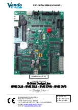
KX-TG6323C SCHEMATIC DIAGRAM (Base Unit_Main)

NC: No Components

Summary of Contents for KX-TGA631CS

Page 1: ...d All rights reserved Unauthorized copying and distribu tion is a violation of law ORDER NO KM40803543CE F22 Telephone Equipment Model No KX TG6323CPK KX TGA631CS Expandable Digital Cordless Answring System Pearl Silver Version for Canada ...

Page 2: ...2 KX TG6323CPK KX TGA631CS ...

Page 3: ... 1 Connections 7 5 2 Battery 7 6 Operating Instructions 9 6 1 Programmable Settings 9 6 2 Error Messages 12 6 3 Troubleshooting 13 7 Schematic Diagram 17 7 1 For Schematic Diagram 17 7 2 Schematic Diagram Base Unit_Main 18 7 3 Schematic Diagram Base Unit_RF Part 20 7 4 Schematic Diagram Handset_Main 22 7 5 Schematic Diagram Handset_RF Part 24 7 6 Schematic Diagram Charger Unit 25 8 Exploded View a...

Page 4: ...d wire assembly shall be replaced 3 FASTON terminals shall be plugged straight in and unplugged straight out ICs and LSIs are vulnerable to static electricity When repairing the following precautions will help prevent recurring malfunctions 1 Cover plastic parts boxes with aluminum foil 2 Ground the soldering irons 3 Use a conductive mat on worktable 4 Do not grasp IC or LSI pins with bare fingers...

Page 5: ...5 KX TG6323CPK KX TGA631CS 3 Specifications Note Design and specifications are subject to change without notice Note for Service Optional headset RP TCA86 RP TCA92 RP TCA94 RP TCA95 ...

Page 6: ...6 KX TG6323CPK KX TGA631CS 4 Location of Controls and Components 4 1 Controls 4 1 1 Base Unit 4 1 2 Handset 4 2 Display ...

Page 7: ...7 KX TG6323CPK KX TGA631CS 5 Installation Instructions 5 1 Connections 5 2 Battery 5 2 1 Battery Installation and Replacement ...

Page 8: ...indicated correctly if the battery is disconnected and connected again even after it is fully charged In that case by recharging the battery as mentioned above you will get a correct indication of the battery strength 5 2 3 Battery Level 5 2 4 Panasonic Ni MH Battery Performance supplied batteries ...

Page 9: ...9 KX TG6323CPK KX TGA631CS 6 Operating Instructions 6 1 Programmable Settings 6 1 1 Programming by Scrolling through the Display Menus ...

Page 10: ...10 KX TG6323CPK KX TGA631CS 6 1 2 Programming using the Direct Commands ...

Page 11: ...11 KX TG6323CPK KX TGA631CS ...

Page 12: ...12 KX TG6323CPK KX TGA631CS 6 2 Error Messages ...

Page 13: ...13 KX TG6323CPK KX TGA631CS 6 3 Troubleshooting ...

Page 14: ...14 KX TG6323CPK KX TGA631CS ...

Page 15: ...15 KX TG6323CPK KX TGA631CS ...

Page 16: ...16 KX TG6323CPK KX TGA631CS ...

Page 17: ... with the development of new technology 7 1 2 Handset Schematic Diagram Handset_Main Notes 1 DC voltage measurements are taken with an oscilloscope or a tester with a ground 2 The schematic diagrams may be modified at any time with the development of new technology 7 1 3 Charger Unit Schematic Diagram Charger Unit Notes 1 DC voltage measurements are taken with voltmeter from the negative voltage l...

Page 18: ...901 ANT3 13 824M X501 NC R595 NC R596 ANT1_HOT2 ANT2_HOT2 P15 10p C472 10p C473 ANT1 ANT2 R674 220 R672 L501 0 C475 4 NC TXMOD 5 NC1 6 XIN 7 XOUT 8 VDD 9 VCCIN 10 GND1 11 RSTN 12 FLASH_RE 13 FLASH_SO 14 FLASH_SI 15 FLASH_CS 16 NC2 17 SYN_OUT 18 TX_DATA 19 SLOT_CTRL 20 NC3 21 NC4 22 NC5 29 SYN_CLK 30 SYN_DATA 31 NC8 32 NC9 33 FCCP15 34 RX_DATA 35 NC10 36 NC11 37 NC12 38 RF_RSTN 39 NC13 40 NC14 41 N...

Page 19: ...C102 680p NC R115 6 3 330u C341 16 100u C306 DCP DCM L1T L1R 0 1u C452 Q156 NC B C E D361 22V A K Q362 B C E D142 NC A K Q111 B C E D113 A K Q161 B C E Q171 B C E D133 A K D153 A K 0 R362 C_DCP C_DCM R372 6 8 NC L372 NC R373 470nH L362 C331 K0 47 100k R172 K1 0 C342 K0 01 C152 10M R151 D300 NC Q300 D301 390 R181 56 R182 C181 0 1u 27 4532 R167 22 R171 MIC1 1 2 82 R160 12 R163 2 7k R164 820 R168 C18...

Page 20: ...R763 NC R762 NC R761 NC R715 NC C739 NC C764 D771 1 2 3 D781 1 2 3 K1uF C714 3 0V 1 VIN 2 VSS 3 CE 5 VOUT 4 NC B1 0p C792 B1 0p C796 3 9n L795 3 9n L791 B2 0p C777 B2 0p C775 B1 5p C776 B3 3p C751 D10p C765 B0 7p C763 1 VCC_VCO 2 PAEN 9 TX_p 3 ATST_p 4 ATST_n 5 ANT_n 6 TRSW 7 Rxp 8 Rxn 10 TX_n 11 TRSW_n 12 ANT 13 VCC_FE 14 VDD_IF 15 VCC_IF 16 VDD_DIG_b 17 VCC_DIG 18 RSTN 19 VCC_IO 20 TR_DATA 21 RA...

Page 21: ...tion ANS1 1 2 STOP 1 2 ERASE 1 2 REC 1 2 CHK 1 2 MSG VCC ANS MSG2 1 2 MSG1 1 2 RPT 1 2 SKIP 1 2 UP 1 2 DOWN 1 2 LOCAT INT 1 2 LED902 A K LED901 A K MEG_LED KEYIN2 KEYS_B ANS_LED KEYS_E KEYS_C KEYIN1 2APVCC KEYIN3 KEYS_D KX TG6323 SCHEMATIC DIAGRAM Base Unit_Operation ...

Page 22: ... GND2 10 GND3 11 GND4 12 GND5 13 RST 14 FL_RST 15 FL_DO 16 FL_DI 17 FL_CS 18 BL_LED 19 SYN_OUT 20 TX_DATA 21 SLOT_CTRL 22 NC2 29 VCC1 30 SYN_EN 31 SYN_CLK 32 SYN_DATA 33 NC4 34 TX_EN 35 NC5 36 RX_DATA 37 NC6 38 CHG_DET 39 NC7 40 LCD_BACK_LIGHT 41 NC8 42 CHG_CTL 43 NC9 44 DB4 45 DB5 46 DB6 47 DB7 54 NC11 55 ANT_LED 56 LCD_RS 57 RW_WR 58 E_RD 59 LCDPOW 60 NC12 61 NC13 62 NC14 63 STB_E 64 STB_D 65 ST...

Page 23: ...52 NC L352 1 2 R370 BATTN NC L351 NC R375 120 R367 VSS2 CHG1 K0 1 C374 CHG2 47k R363 NC C351 NC D531 A K 33k R369 K0 1 C362 VSS1 100k R437 1k R436 5 6n F301 Q531 B C E Q361 B E C 560 R362 3 3k R366 NC C353 Q362 B C E NC L412 NC L413 Q364 B C E RECEIVER 1 2 SP_PHONE 1 2 D361 A K MICM 1 MICP 1 NC C364 K1 0 C421 K1 0 C371 K1 0 C372 2 7V 1 VIN 2 VSS 3 ONOFF 5 VOUT 4 NC K0 1 C363 D364 L4 3V A K 10uH L3...

Page 24: ... NC R763 NC R762 NC R761 NC R715 NC C739 NC C764 D771 1 2 3 D781 1 2 3 RF_POWER K1uF C714 NC C792 NC C796 B2 0p C775 B2 0p C777 B1 5p C776 B3 3p C751 D10p C765 B0 7p C763 1 VCC_VCO 2 PAEN 9 TX_p 3 ATST_p 4 ATST_n 5 ANT_n 6 TRSW 7 Rxp 8 Rxn 10 TX_n 11 TRSW_n 12 ANT 13 VCC_FE 14 VDD_IF 15 VCC_IF 16 VDD_DIG_b 17 VCC_DIG 18 RSTN 19 VCC_IO 20 TR_DATA 21 RADIOEN 22 SLOT_CTRL 23 SYN_DAT 24 SYN_CLK 25 SYN...

Page 25: ...25 KX TG6323CPK KX TGA631CS 7 7 Schematic Diagram Charger Unit J1 2 1 TP3 G TP2 TP1 TP4 R1 10 D1 A K F1 SCHEMATIC DIAGRAM Charger Unit ...

Page 26: ...replacing any of these com ponents only use specified manufacture s parts 3 ISO code Example ABS 94HB of the remarks column shows quality of the material and a flame resisting grade about plas tics Note 1 You can download and refer to the Operating Instructions Instruction book on TSN Server 8 1 KX TG6323CPK K T KXTG6323CPK KXTGA631CS Safety Ref No Part No Part Name Description Remarks A1 PQLV207T...

Reviews: