


64
KX-TG4021LAT/KX-TG4022LAT/KX-TG4023LAT/KX-TGA403LAT
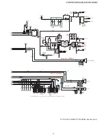
14 Schematic Diagram
14.1. For Schematic Diagram
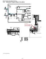
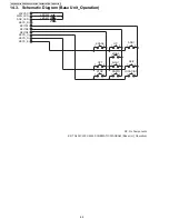
14.1.1. Base Unit (Schematic Diagram (Base Unit_Main))
Notes:
1. DC voltage measurements are taken with voltmeter from the negative voltage line.
2. The schematic diagrams may be modified at any time with the development of new technology.
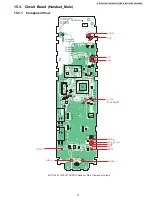
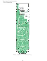
14.1.2. Handset (Schematic Diagram (Handset_Main))
Notes:
1. DC voltage measurements are taken with an oscilloscope or a tester with a ground.
2. The schematic diagrams may be modified at any time with the development of new technology.
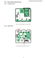
14.1.3. Charger Unit (Schematic Diagram (Charger Unit))
Notes:
1. DC voltage measurements are taken with voltmeter from the negative voltage line.
2. The schematic diagrams may be modified at any time with the development of new technology.
Summary of Contents for KX-TGA403LAT
Page 2: ...2 KX TG4021LAT KX TG4022LAT KX TG4023LAT KX TGA403LAT ...
Page 23: ...23 KX TG4021LAT KX TG4022LAT KX TG4023LAT KX TGA403LAT 4 9 Signal Route ...
Page 24: ...24 KX TG4021LAT KX TG4022LAT KX TG4023LAT KX TGA403LAT RF part signal route ...
Page 28: ...28 KX TG4021LAT KX TG4022LAT KX TG4023LAT KX TGA403LAT 8 1 2 Handset ...
Page 44: ...44 KX TG4021LAT KX TG4022LAT KX TG4023LAT KX TGA403LAT ...
Page 45: ...45 KX TG4021LAT KX TG4022LAT KX TG4023LAT KX TGA403LAT 11 1 2 Handset ...
Page 46: ...46 KX TG4021LAT KX TG4022LAT KX TG4023LAT KX TGA403LAT 11 1 3 Charger Unit ...
Page 65: ...65 KX TG4021LAT KX TG4022LAT KX TG4023LAT KX TGA403LAT Memo ...
Page 69: ...69 KX TG4021LAT KX TG4022LAT KX TG4023LAT KX TGA403LAT Memo ...
Page 76: ...76 KX TG4021LAT KX TG4022LAT KX TG4023LAT KX TGA403LAT Memo ...
Page 83: ...83 KX TG4021LAT KX TG4022LAT KX TG4023LAT KX TGA403LAT 16 4 Accessories A2 A3 A1 ...


