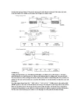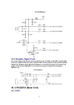
telephone company requirements.
13.16. Intercom Mode
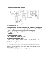
1. When the base unit LOCATOR/INTERCOM button is pressed, a call
monitor signal (intercom sound) is output from pins 32 and 33 of
IC501. Thus a monitor tone is heard from the speaker.
2. “Paging” is displayed on LCD. This status is called “Intercom
stand-by”.
3. The receiving signal flows:
RF pin 32 and 33 of IC501 SP
4. The transmission signal flows:
MIC C474 C475 C476 R476 pin 47 of IC501 RF
13.17. Initializing Circuit
Function:
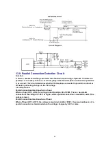
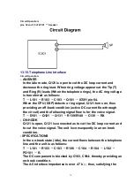
This circuit is used for to initialize the microcomputer when it incorporates an AC adaptor.
Circuit Operation:
When the AC Adaptor is inserted into the unit, then the voltage is shifted by IC301, D509 and
power is supplied to the DSP.
The set can operate beyond point A in the circuit voltage diagram.
71
Summary of Contents for KX-TG2583S
Page 3: ...3 ...
Page 4: ...1 2 Handset 2 DISPLAYS 4 ...
Page 5: ...3 SETTINGS 3 1 Connections 5 ...
Page 6: ...3 2 Adding Another Phone 6 ...
Page 7: ...3 3 Battery Charge 3 3 1 Battery strength 3 3 2 Recharge 7 ...
Page 8: ...3 3 3 Battery information 3 4 Selecting the Dialing Mode 8 ...
Page 9: ...3 5 Selecting the Line Mode 9 ...
Page 10: ...4 PREPARING THE ANSWERING SYSTEM 4 1 Day and Time Adjustment 10 ...
Page 11: ...11 ...
Page 12: ...5 OPERATION 5 1 Making Calls 5 1 1 With the Handset 12 ...
Page 13: ...13 ...
Page 14: ...5 1 2 With the Base Unit Digital Duplex Sperkerphone 14 ...
Page 15: ...15 ...
Page 16: ...5 2 Answering Calls 16 ...
Page 17: ...5 3 Flash Button 17 ...
Page 18: ...5 4 Listening to Message 18 ...
Page 19: ...19 ...
Page 22: ...5 5 3 Viewing the caller list 22 ...
Page 23: ...23 ...
Page 25: ...5 5 5 2 With the base unit 25 ...
Page 26: ...5 5 6 Storing caller list information in the directory 26 ...
Page 27: ...5 5 7 Erasing caller list information 27 ...
Page 28: ...28 ...
Page 29: ...6 DISASSEMBLY INSTRUCTIONS 29 ...
Page 30: ...30 ...
Page 32: ...7 2 Asseembly the LCD to P C Board Handset 32 ...
Page 33: ...7 3 How To Check Splash Resistance 33 ...
Page 36: ...8 1 Check Power 36 ...
Page 37: ...8 2 Error Message Table NOTE Flash memory is IC571 DSP is IC501 37 ...
Page 38: ...8 3 Check Record 8 4 Check Playback 8 5 Check SP phone Voice Transmission 38 ...
Page 39: ...8 6 Check SP phone Voice Reception 8 7 Check Battery Charge 39 ...
Page 48: ...8 10 Check Handset Voice Transmission 48 ...
Page 49: ...8 11 Check Handset Voice Reception 49 ...
Page 50: ...8 12 Check Call ID 50 ...
Page 51: ...9 TEST MODE AND ADJUSTMENT 9 1 Test Mode Flow Chart for Base Unit 51 ...
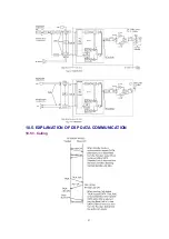
Page 57: ...10 5 EXPLANATION OF DSP DATA COMMUNICATION 10 5 1 Calling 57 ...
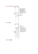
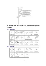
Page 58: ...10 5 2 To Terminate Communication 10 5 3 Ringing 10 5 4 ID CHANGE 58 ...
Page 59: ...11 TERMINAL GUIDE OF IC S TRANSISTORS AND DIODES 11 1 Base Unit 11 2 Handset 59 ...
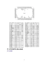
Page 75: ...17 CPU DATA Handset 17 1 IC201 75 ...
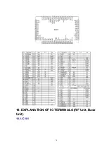
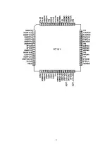
Page 76: ...18 EXPLANATION OF IC TERMINALS RF Unit Base Unit 18 1 IC101 76 ...
Page 77: ...77 ...
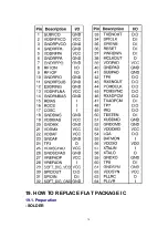
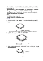
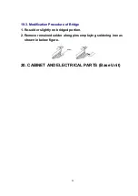
Page 78: ...19 HOW TO REPLACE FLAT PACKAGE IC 19 1 Preparation SOLDER 78 ...
Page 81: ...81 ...
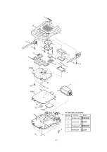
Page 82: ...21 CABINET AND ELECTRICAL PARTS Handset 82 ...
Page 103: ... Ýïïð Ýïðë Ýïïí Ýïïî Ýïðç Ýïïì Ýïðï Ýïðê ...
Page 104: ......
Page 106: ...ÍÐ ØÔÜ Í ð ç è é ê ë ì í î ï ÝÔÎ ÐßË ÚÔÍ ÎÜÔ ÔÝÌ ÎÒÙ ÛÒÌ ÛÈÌ ÜÉÒ Î ÙØÌ ËÐ ÍÌÐ ÓÍÙ ÔÛÚÌ ...
Page 108: ... Ýëëï Þ Û Ý Þ Û Ý ...
Page 109: ... Ýîðï Û Þ Ý Û Þ Ý Û Þ Ý Û Þ Ý Û Þ Ý Û Þ Ý Þ Û Ý Þ Û Ý Ýîðî Û Þ Ý Þ Û Ý ÎÚ ËÒ Ì Ýîðì Ýîðí Ýîðë ...
Page 112: ...Ýèðï Ýèðé Ýèðè Ýèðì Ýèðí Ýèðî Ýèðë Ýèðê Îèðî Îèðï ...
Page 114: ...Þ Û Ý ÎÚ ËÒ Ì ÍÉ ÑÚÚ Ò Ó ÍÉ ÑÒ ÌÛÍÌ Ó øØ ÙÒÜ ÍÉ ÍÁÔÑÉ ...

