background image

30

Summary of Contents for KX-TG2583S

Page 1: ...DER NO KM40101757C7 F12 Telephone Equipment KX TG2583B KX TG2583S KX TG2583W 2 4GHz Cordless Answering System Black Version Silver Version Pearl White Version for U S A for Latin America SPECIFICATIONS 1 ...

Page 2: ...2001 Kyushu Matsushita Electric Co Ltd All rights reserved Unauthorized copying and distribution is a violation of law 1 LOCATION OF CONTROLS 1 1 Base Unit 2 ...

Page 3: ...3 ...

Page 4: ...1 2 Handset 2 DISPLAYS 4 ...

Page 5: ...3 SETTINGS 3 1 Connections 5 ...

Page 6: ...3 2 Adding Another Phone 6 ...

Page 7: ...3 3 Battery Charge 3 3 1 Battery strength 3 3 2 Recharge 7 ...

Page 8: ...3 3 3 Battery information 3 4 Selecting the Dialing Mode 8 ...

Page 9: ...3 5 Selecting the Line Mode 9 ...

Page 10: ...4 PREPARING THE ANSWERING SYSTEM 4 1 Day and Time Adjustment 10 ...

Page 11: ...11 ...

Page 12: ...5 OPERATION 5 1 Making Calls 5 1 1 With the Handset 12 ...

Page 13: ...13 ...

Page 14: ...5 1 2 With the Base Unit Digital Duplex Sperkerphone 14 ...

Page 15: ...15 ...

Page 16: ...5 2 Answering Calls 16 ...

Page 17: ...5 3 Flash Button 17 ...

Page 18: ...5 4 Listening to Message 18 ...

Page 19: ...19 ...

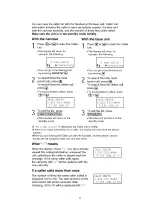
Page 20: ...ll be shown on the handset and base unit displays after the first ring The unit can record information of up to 50 different callers in the Caller List The Caller List information is sorted by the most recent to the oldest call When the 51st call is received the first call is deleted Using the list you can automatically call back a caller You can store the caller s names and 20 ...

Page 21: ...scribe to both Caller ID and Call Waiting services when a second call is received while talking the new caller s name and phone number will be displayed 5 5 1 How caller information is displayed when a call is received 5 5 2 To check the number of new calls 21 ...

Page 22: ...5 5 3 Viewing the caller list 22 ...

Page 23: ...23 ...

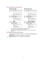
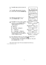
Page 24: ...5 5 4 Calling back from the caller list 5 5 5 Editing the caller s phone number 5 5 5 1 With the handset 24 ...

Page 25: ...5 5 5 2 With the base unit 25 ...

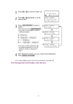
Page 26: ...5 5 6 Storing caller list information in the directory 26 ...

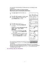
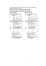
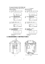
Page 27: ...5 5 7 Erasing caller list information 27 ...

Page 28: ...28 ...

Page 29: ...6 DISASSEMBLY INSTRUCTIONS 29 ...

Page 30: ...30 ...

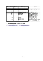
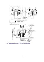
Page 31: ...eration P C Board Screws 2 6 8 B 6 4 4 4 Battery Cover Remove the Battery Cover 5 4 5 5 Rear Cabinet Screws 2 6 12 C 2 Screws 2 8 D 2 Screw 2 6 12 E 1 6 4 6 6 Antenna Screw 2 6 12 F 1 Main P C Board Screws 2 8 G 4 7 4 7 7 Main P C Board Pull the Charge Terminals outside Remove the Main P C Board 7 ASSEMBLY INSTRUCTIONS 7 1 Assembly the LCD to P C Board Base Unit 31 ...

Page 32: ...7 2 Asseembly the LCD to P C Board Handset 32 ...

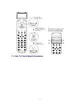
Page 33: ...7 3 How To Check Splash Resistance 33 ...

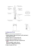
Page 34: ...speaker cables of LCD unit on HS main board And remove LCD unit 2 Remove solder on six legs of RF unit 3 Remove solder on all pads of RF unit 4 Replace defective RF unit with new HS RF unit NOTE Do not use BU RF unit for HS one HS RF unit is different from BU one 5 Solder all pads of RF unit 34 ...

Page 35: ...6 Solder six RF legs 7 Put LCD unit and solder speaker wire NOTE Speaker wire has polarity Component View Solder Side View 8 TROUBLESHOOTING GUIDE 35 ...

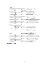
Page 36: ...8 1 Check Power 36 ...

Page 37: ...8 2 Error Message Table NOTE Flash memory is IC571 DSP is IC501 37 ...

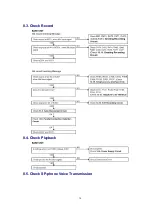
Page 38: ...8 3 Check Record 8 4 Check Playback 8 5 Check SP phone Voice Transmission 38 ...

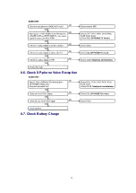
Page 39: ...8 6 Check SP phone Voice Reception 8 7 Check Battery Charge 39 ...

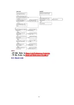
Page 40: ...NOTE CP CM Refer to Base Unit Reference Drawing TP BL Refer to Handset Reference Drawing 8 8 Check Link 40 ...

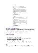
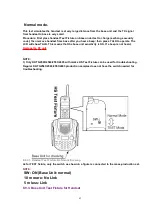
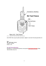
Page 41: ...e linked How to confirm the link is as follows press the TALK button and confirm Handset in use is displayed on BU LCD 8 9 2 Handset Test Fixture for Base Unit Test Fixture has two mode 1 TEST mode RF Power Low mode The switch of Test Fixture changed with TEST mode side Then Test Fixture is in TEST mode 2 Normal mode RF Power Normal mode The switch of Test Fixture changed with Normal mode side The...

Page 42: ... This means that the base unit sensitivity is OK If a beep is not heard Replace the RF unit NOTE 1 Only KX TG2583 2563 2553 2403 with marks HS Test Fixture can be used for troubleshooting Regular KX TG2583 2563 2553 2403 production samples does not have the switch needed for troubleshooting 8 9 2 1 Handset Test Fixture Reference Drawing As for TEST fixture only the switch as shown in a figure is c...

Page 43: ...r not This test simulates the handset is at very large distance from the base unit and the TX signal from base to handset is very small Procedure First place handset under test to charge exchange security code then remove handset from base after you hear a beep Press TALK button on handset and if it links with the base then this handset sensitivity is OK If a beep is not heand Replace the RF unit ...

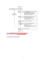
Page 44: ...nly the switch as shown in a figure is connected to the mass production set Note SW ON Handset Nomal 10m more No Link 5m less Link 8 9 4 RF Check Flowchart Each item 1a 6 of RF Check Flowchart is correspond to Check Table for RF Block Please refer each item one by one 44 ...

Page 45: ... 1 See RF Unit Reference Drawing Base Unit and Handset 2 Base unit RF only refer to Check Table for RF Block 8 9 5 Check Table for RF Block 45 ...

Page 46: ...soldering 2 24MHz Adjustment 1 Set BU to Test STANDBY mode 5 2 Confirm X101 frequency within 24MHz 720Hz at TP_FREQ 4 of RF Unit If X101 frequency is spec out than adjust frequency within 24 MHz 100 Hz by VC101 1 Set HS to Test STANDBY mode 2 Confirm X101 frequency within 24MHz 720Hz at TP_FREQ Unit If X101 frequency is spec out adjust frequency within 24 MHz Hz by VC101 3 TX Pow_Low confirmation ...

Page 47: ...e Unit HS Handset 2 See Base Unit Reference Drawing 3 See Handset Reference Drawing 4 See RF Unit Reference Drawing Base Unit and Handset 5 See TEST MODE AND ADJUSTMENT 8 9 6 RF DSP Interface Signal Wave Form 47 ...

Page 48: ...8 10 Check Handset Voice Transmission 48 ...

Page 49: ...8 11 Check Handset Voice Reception 49 ...

Page 50: ...8 12 Check Call ID 50 ...

Page 51: ...9 TEST MODE AND ADJUSTMENT 9 1 Test Mode Flow Chart for Base Unit 51 ...

Page 52: ... 1 See Base Unit Reference Drawing 2 Special check method for Base Unit individually 9 2 Key Check Mode 1 See Base Unit Reference Drawing 9 3 Test Mode Flow Chart for Handset 52 ...

Page 53: ...r to Test Mode Flow Chart for Handset DC power supply and Battery connector are required in this adjustment 1 Set 3 9V for DC power supply 2 Place handset in test mode 3 Press TALK key 4 times to TX Low mode CW Tx Low is displayed on LCD 4 Set 3 51V for DC power supply Check voltage at battery connector because some voltage drop is happened using long or thin cable 5 Press key to write voltage val...

Page 54: ...ing and receiving channel between base unit and handset is same frequency Refer to the Frequency Table 10 2 Time Division Duplex TDD operation Transmission reception between the base unit and handset is performed by time sharing as shown in Fig 7 1 slot time of transmission and reception is 1mS Same frequency is used in transmitting and receiving The figure shows an example the frequency of 1ch is...

Page 55: ...th the 8 bit sync word and 8 bit data channel are programmable via the DSP interface In addition the 64 bit payload can be filled either with ADPCM voice data or can be used by the host DSP as a fast data channel between base and handset 10 3 Spread Spectrum Transmission and reception are operated using the spread spectrum method DSS Digital Spread Spectrum Mixing the original signal with the pseu...

Page 56: ...gh filter L107 and the balun T101 to perform the de spread then input to DSP IC201 DSP performs ADPCM decoding to convert the signal into the voice signal then it is output to the speaker Transmission The voice signal input from the microphone is led to DSP IC201 The DSP generates ADPCM signal As well as the reception it is converted into the RF signal by RFIC IC101 Passing through the balun T101 ...

Page 57: ...10 5 EXPLANATION OF DSP DATA COMMUNICATION 10 5 1 Calling 57 ...

Page 58: ...10 5 2 To Terminate Communication 10 5 3 Ringing 10 5 4 ID CHANGE 58 ...

Page 59: ...11 TERMINAL GUIDE OF IC S TRANSISTORS AND DIODES 11 1 Base Unit 11 2 Handset 59 ...

Page 60: ... RX Circuit Circuit Operation Telephone Line T R R139 R140 C139 C449 R448 C441 Q461 C442 R442 pin 38 of IC501 pins 32 and 33 of IC501 Speaker 13 2 SP PHONE TX Circuit Circuit Operation MIC C474 C475 C476 R476 pin 47 of IC501 pin 36 of IC501 R431 C432 C433 Telephone Line 60 ...

Page 61: ...ceiving status or OGM transmitting status Circuit Operation The voltage pin 40 of IC501 is monitored If a parallel connected telephone is put into an OFF HOOK status the presence absence of a parallel connection is determined when the voltage changes by 0 2V or more When the set detects the parallel connected telephone is OFF HOOK status the line is disconnected 61 ...

Page 62: ... 4 1 V The voltage at point C is dropped by D521 to 3 8 V The voltage at point D is dropped by Q315 to 4 0V The voltage at point E is dropped by Q601 to 3 6V 13 5 DTMF Signal When the DTMF data from the Handset is received the DTMF signal is output from pin 36 of IC501 and sent to the line through Q131 13 6 Line Sending Signal The coded signal input from the RF unit is decoded by IC501 The audio s...

Page 63: ...13 7 Line Receiving Signal The audio signal from line passes through Q131 and Q461 to pin38 and 39 of IC501 DSP IC501 modulates this input audio signal to output to the RF unit 63 ...

Page 64: ...a caller ID service contract has been entered for the circuit being used The data for the caller ID from the telephone exchange is sent during the interval between the first and second rings of the bell signal The data from the telephone exchange is a modem signal which is modulated in an FSK Frequency Shift Keying format Data 0 is a 1200 Hz sine wave and data 1 a 2200 Hz sine wave There are two t...

Page 65: ...es place almost immediately after the customer is alerted to the new call so he she can use this information to decide whether to take the new call Function The CAS signal flows from T R R111 R112 C111 C112 IC501 pins 41 43 and the ACK DTMF signal is returned to the telephone exchange The telephone exchange that received the ACK can send the data in the same manner as the caller ID If the unit dee...

Page 66: ...hook or off hook by detecting changes in the T R voltage Circuit Operation Parallel connection detection when on hook When on hook Q115 is ON the voltage is monitored pin 40 of IC501 There is no parallel connection if the voltage is 1 65 V or higher while a parallel connection is deemed to exist if the voltage is lower Parallel connection detection when off hook When off hook Q115 is OFF the volta...

Page 67: ...s activation and control of all that functions such as speech Recording Playback Tone detecting and Line monitoring The DSP system comprises of following a Host Processor a Digital Signal Processor which includes the firmware implemented functions a FLASH MEMORY IC571 which is used for stored voice messages and synthesized voice Voice Message Recording The DSP system use a proprietary speech compr...

Page 68: ...ORY IC571 which stored the vocabulary Caller ID and Call Waiting CID demodulation The DSP implements monitor and demodulate the FSK signals that provide CID information from the Central Office Transmit and Receive ADPCM Data This DSP implement ADPCM 13 11 Greeting Recording Circuit Circuit Operation MIC C474 C475 C476 R476 pin 47 of IC501 When Pin82 of IC501 is Low Greeting recording 13 12 Greetin...

Page 69: ...13 13 ICM Recording Circuit Circuit Operation Telephone Line Q131 C463 R448 C442 R464 C441 pin 38 and 39 of IC501 13 14 ICM Play Circuit 69 ...

Page 70: ... providing an off hook condition active DC current flow through the circuit and the following signal flow is for the voice signal T D101 Q121 Q131 R139 R140 C139 RX ON HOOK Q121 is open Q121 is connected as to cut the DC loop current and to cut the voice signal The unit is consequently in an on hook condition SPECIFICATIONS In the on hook state idle the current flows between the telephone line and...

Page 71: ...tercom stand by 3 The receiving signal flows RF pin 32 and 33 of IC501 SP 4 The transmission signal flows MIC C474 C475 C476 R476 pin 47 of IC501 RF 13 17 Initializing Circuit Function This circuit is used for to initialize the microcomputer when it incorporates an AC adaptor Circuit Operation When the AC Adaptor is inserted into the unit then the voltage is shifted by IC301 D509 and power is supp...

Page 72: ...h IC761 to switch another Antenna Antenna selection control by IC501 is available only in test mode 14 BLOCK DIAGRAM Handset 15 CIRCUIT OPERATION Handset 15 1 Power Supply Circuit Voltage is supplied separately to each block 15 2 Charge Circuit Ni cd battery is connected to CN202 When the handset is put on the cradle of the base unit the power is supplied from CHARGE1 and CHARGE2 terminals to char...

Page 73: ... high Q208 turns on and results in a louder beep tone 15 4 Sending Signal The voice signal from the microphone input to pin 42 CIDIP and pin 41 CIDIN of IC201 DSP CN203 is the headphone jack When the headphone is connected the Q206 detect it The input from the microphone of the handset CIDIN CIDIP is cut and the microphone signal from the headphone is input to pin 47 of IC201 HMIN Also the power f...

Page 74: ...P as the voice signal SPN is the inverse output of SPP and the speaker is driven by SPN and SPP CN203 is the headphone jack When the headphone is connected to this jack the output to the speaker of the handset SPN SPP is cut and the voice signal is output to the headphone HSOUT only 16 CPU DATA Base Unit 16 1 IC501 74 ...

Page 75: ...17 CPU DATA Handset 17 1 IC201 75 ...

Page 76: ...18 EXPLANATION OF IC TERMINALS RF Unit Base Unit 18 1 IC101 76 ...

Page 77: ...77 ...

Page 78: ...19 HOW TO REPLACE FLAT PACKAGE IC 19 1 Preparation SOLDER 78 ...

Page 79: ...iron but beginner might damage foil by overheating Flux HI115 Specific gravity 0 863 Original flux will be replaced daily 19 2 Procedure 1 Temporary fix FLAT PACKAGE IC by soldering on two marked 2 pins Most important matter is accurate setting of IC to the corresponding soldering foil 2 Apply flux for all pins of FLAT PACKAGE IC 3 Solder employing specified solder to direction of arrow as sliding...

Page 80: ...3 Modification Procedure of Bridge 1 Re solder slightly on bridged portion 2 Remove remained solder along pins employing soldering iron as shown in below figure 20 CABINET AND ELECTRICAL PARTS Base Unit 80 ...

Page 81: ...81 ...

Page 82: ...21 CABINET AND ELECTRICAL PARTS Handset 82 ...

Page 83: ...lable for a specific period of time The retention period of availability is dependent on the type of assembly and in accordance with the laws governing part and product retention After the end of this period the assembly will no longer be available 2 Important safety notice Components identified by a mark special characteristics important for safety When replacing any of these components use only ...

Page 84: ...SISTORS CAPACITORS Unless otherwise specified All resistors are in ohms K 1000 M 1000k All capacitors are in MICRO FARADS F P F Type Wattage of Resistor 23 1 Base Unit 23 1 1 CABINET AND ELECTRICAL PARTS 84 ...

Page 85: ... TG2583B S 13 PQYM10112Z2 UPPER CABINET for KX TG2583S S 13 PQYM10112Z4 UPPER CABINET for KX TG2583W S 14 PQSA10109Y ANTENNA for KX TG2583B for KX TG2583S 14 PQSA10109X ANTENNA for KX TG2583W 15 PQSA10110Y ANTENNA for KX TG2583B for KX TG2583S 15 PQSA10110X ANTENNA for KX TG2583W 16 PQSX10168Z RUBBER SWITCH DIAL for KX TG2583B for KX TG2583S 16 PQSX10168Y RUBBER SWITCH DIAL for KX TG2583W 17 PQSX1...

Page 86: ...OR SI Q371 2SD2136 TRANSISTOR SI Q381 2SD1819A TRANSISTOR SI Q445 2SD1819A TRANSISTOR SI Q451 PQVTDTC123JU TRANSISTOR SI S Q461 2SD1819A TRANSISTOR SI Q485 2SD1819A TRANSISTOR SI Q577 UN5213 TRANSISTOR SI S Q601 2SD1994A TRANSISTOR SI Q611 2SD1994A TRANSISTOR SI Q621 2SD2137 TRANSISTOR SI DIODES D101 PQVDS1ZB60F1 DIODE SI S D103 MA111 DIODE SI D117 MA111 DIODE SI D118 MA111 DIODE SI D121 PQVDRLZ20...

Page 87: ...A102 PQVDDSS301L SURGE ABSORBER OTHERS X501 PQVCK4096N9Z CRYSTAL OSCILLATOR S E1 PQJM146Y MICROPHONE E2 PQMG10025Z CUSHION RUBBER MIC E3 PQJE10113Z FFC P101 PQRPAR390N POSISTOR S G601 PQJT10152Z CHARGE TERMINAL G602 PQJT10152Z CHARGE TERMINAL G603 PQJT10152Z CHARGE TERMINAL G604 PQJT10152Z CHARGE TERMINAL G605 PQJT10152Z CHARGE TERMINAL G606 PQJT10152Z CHARGE TERMINAL RESISTORS R103 ERJ3GEYJ104 10...

Page 88: ...GEYJ220 22 R377 ERDS1TJ221 220 S R378 ERDS1TJ221 220 S R381 ERJ3GEYJ563 56k R382 ERJ3GEYJ563 56k R383 ERJ3GEYJ103 10k R384 ERJ3GEYJ104 100k R411 ERJ3GEYJ394 390k R412 ERJ3GEYJ394 390k R413 ERJ3GEYJ103 10k R414 ERJ3GEYJ103 10k R415 ERJ3GEYJ473 47k R431 ERJ3GEYJ222 2 2k R433 ERJ3GEYJ393 39k R442 ERJ3GEYJ682 6 8k R443 ERJ3GEYJ103 10k R444 ERJ3GEYJ332 3 3k R445 ERJ3GEYJ564 560k R446 ERJ3GEYJ105 1M R44...

Page 89: ... 820 R664 ERJ3GEYJ180 18 R666 ERJ3GEYJ180 18 R751 ERJ3GEYJ103 10k R753 ERJ3GEYJ104 100k R754 ERJ3GEYJ104 100k CAPACITORS C101 ECKD2H681KB 680P S C102 ECKD2H681KB 680P S C103 PQCUV1H154KR 0 15 C104 PQCUV1H154KR 0 15 C106 PQCUV1A684KB 0 68 C111 ECKD2H681KB 680P S C112 ECKD2H681KB 680P S C115 ECUV1H103KBV 0 01 C121 ECUV1H103KBV 0 01 C131 ECUV1H101JCV 100P C132 ECUV1H103KBV 0 01 C134 ECEA1HKS100 10 S ...

Page 90: ...V1H070CCV 7P C461 ECUV1C104ZFV 0 1 C464 ECUV1H101JCV 100P C467 ECUV1H070CCV 7P C471 ECUV1A105ZFV 1 C472 ECST0JY475 4 7 C474 ECUV1A224KBV 0 22 C475 PQCUV1H154KR 0 15 C476 ECUV1A224KBV 0 22 C477 ECUV1H221JCV 220P C481 ECUV1H070CCV 7P C482 ECUV1H070CCV 7P C483 ECUV1H070CCV 7P C488 ECUV1H102KBV 0 001 C501 ECEA0JU102 1000 C502 ECUV1C104ZFV 0 1 C503 ECUV1C104ZFV 0 1 C504 ECUV1C104ZFV 0 1 C505 ECUV1C104Z...

Page 91: ...C104ZFV 0 1 C760 ECUV1H070CCV 7P C761 ECUV1H070CCV 7P C763 ECUV1H070CCV 7P C764 ECUV1H070CCV 7P 23 1 3 OPERATIONAL P C BOARD PARTS Ref No Part No Part Name Description Remarks PCB2 PQWP2G2583BH OPERATION P C BOARD LEDS LED841 PQVDBR1111C LED S LED842 PQVDBR1111C LED S LED843 PQVDSML310MT LED S LED844 PQVDBR1111C LED S CONNECTORS CN801 PQJS30B37Z CONNECTOR SOCKET S CN802 PQJS22B11Z FPC CONNECTOR RE...

Page 92: ...ACKING SHEET EP CAP 116 PQHS10485Z CUSHION SPEAKER 117 PQHX10862Z LCD COVER SHEET 118 PQHX10934Z SHEET 119 PQHX10959Z RF SPONGE 120 PQJT10175Z CHARGE TEMRINAL 121 PQKE10128Z1 EARPHONE CAP for KX TG2583B for KX TG2583S S 121 PQKE10128Z2 EARPHONE CAP for KX TG2583W S 122 PQKE10129Z1 COVER for KX TG2583B for KX TG2583S S 122 PQKE10129Z2 COVER for KX TG2583W S 123 PQP508SVC BATTERY S 124 PQQT22212Z CH...

Page 93: ...D212 MA8150 DIODE SI D213 MA8150 DIODE SI D214 PQVD1SR154 DIODE SI S D215 MA2ZD1400 DIODE SI D216 PQVD1SR154 DIODE SI S LEDS LED201 PQVDSML310MT LED S LED202 PQVDSML310MT LED S LED203 PQVDSML310MT LED S LED204 PQVDSML310MT LED S LED205 PQVDSML310MT LED S LED206 PQVDSML310MT LED S LED207 PQVDSML310MT LED S CONNECTORS CN201 PQJS22B11Z FPC CONNECTOR CN202 PQJP2D13Z CONNECTOR PIN S CN203 PQJJ1J007Z EA...

Page 94: ...J3GEYJ224 220k R229 ERJ3GEYJ102 1k R230 ERJ3GEYJ102 1k R231 ERJ3GEYJ102 1k R232 ERJ3GEYJ103 10k R233 ERJ3GEY0R00 0 R234 ERJ3EKF2204 0 R235 ERJ3EKF2204 0 R236 ERJ3GEYJ473 47k R241 ERJ3GEY0R00 0 R242 ERJ3GEYJ180 18 R243 ERJ3GEYJ180 18 R244 ERJ3GEYJ473 47k R245 ERJ3GEYJ103 10k R246 ERJ3GEYJ153 15k R247 ERJ3GEYJ391 390 R248 ERJ3GEYJ393 39k R249 ERJ3GEYJ222 2 2k R250 ERJ3GEYJ222 2 2k R251 ERJ3GEYJ120 1...

Page 95: ...C226 ECUV1C104ZFV 0 1 C227 ECUV1H470JCV 47P C228 ECUV1C104ZFV 0 1 C229 ECUV1C104ZFV 0 1 C230 ECUV1C104KBV 0 1 C231 ECUV1A224KBV 0 22 C232 ECUV1C104KBV 0 1 C233 ECUV1C104ZFV 0 1 C234 ECUV1A224KBV 0 22 C236 ECUV1H060DCV 6P S C237 ECUV1H060DCV 6P S C239 ECUV1H103KBV 0 01 C249 ECST0GY226 22 C255 ECUV1A224KBV 0 22 C267 ECST0JY226 22 C270 ECST0JY475 4 7 C274 ECUV1C104ZFV 0 1 C280 ECUV1C104ZFV 0 1 C283 E...

Page 96: ...12 PQXDZLDRS1 SECURITY TAG for KX TG2583S P1 XZB21X35A03 PROTECTION COVER for Base Unit P2 XZB10X35A02 PROTECTION COVER for Handset P3 PQPK13353Z GIFT BOX for KX TG2583B P3 PQPK13344Z GIFT BOX for KX TG2583S P3 PQPK13387Z GIFT BOX for KX TG2583W 24 FOR SCHEMATIC DIAGRAM 24 1 Base Unit SCHEMATIC DIAGRAM Base Unit Notes 1 DC voltage measurements are taken with voltmeter from the negative voltage lin...

Page 97: ...CIRCUIT BOARD OPERATION 28 SCHEMATIC DIAGRAM Operation 29 CIRCUIT BOARD Base Unit 29 1 Component View 29 2 Flow Solder Side View 30 SCHEMATIC DIAGRAM Base Unit 31 CIRCUIT BOARD Handset 31 1 Component View 31 2 Flow Solder Side View 32 SCHEMATIC DIAGRAM Handset M KXTG2583B KXTG2583S KXTG2583W Printed in Japan 97 ...

Page 98: ...ÍÐ ÐØÑÒÛ ÎÈ ÌßÔÕ ÌÈ ÌßÔÕ ÎÈ ºãïòïµØ ïìð Ê ó øóîë Þ ñêðð Ñ ìîð Ê ó óïí Þ êð Ê ó îð Ê ó ïê Ê ó íòëÊ íòéÊ îê Ê ó îî Ê ó ìðð Ê ó éîð Ê ó Ê ÓßÈ ìòïÊ íòèÊ ìòïÊ êòèÊ ìòëÊ ìòïÊ ïïòðÊ éòìÊ ìòðÊ ºãïòïµØ øóëð Þ ñêðð Ê ó ÎÚ Í ÙÒßÔ ÌÈ Ø Ô ª õîð o ì Þ îòìðïë îòìéðë ÙØ ...

Page 99: ...ðì Ýîðí Ýîðë ÌÈ ØñÍ ÎÈ ØñÍ ÌÈ Ò ºãïòïµØ ïè Ê ó øóìë Þ ñêðð ïîð Ê ó óîê Þ ÎÈ Ò ïîð Ê ó óîê Þ îêð Ê ó óïè Þ íòíÊ íòíÊ ïêð Ê ó óîí Þ ºãïòïµØ ïè Ê ó øóìë Þ ñêðð óîè Þ çð Ê ó ÌÈ Ø Ô ª õîð o ì Þ îòìðïë îòìéðë ÙØ ÎÚ Í ÙÒßÔ ...

Page 100: ...Ïíéï Ïíïï Ïêîï éÊ éÊ Ïêðï Ïíïë Ïíìí Ïìêï Ïïïë íòêÊ íòêÊ ÊÐÉÎ ÊÎÚï ÊÎÚî ÐÝÑÒÌ ÎÛÙËÔßÌÑÎ ÑÐ ÝÒëèï ÍÛÙë ÍÛÙì Ïêïï ÍóÔÑÉ ÎÚÁÎÛÍÛÌ ÞÞ ÝÁÐÉÜÒ øÎ ÙØÌ ßÒÌï øÔÛÚÌ ßÒÌî Ýëéï ...

Page 101: ... ÎÛÙ ÎÛÍÛÌ Ïîðë ÍÐóßÓÐ Ïîðè Ïîïð Ýîðìô Ïîðì íòíÊ ÎÛÙ ÝØßÎÙÛ ÝØßÎÙÛ ÜÛÌ ØÛßÜ ÍÛÌ ÖßÝÕ Ó Ý ÍÐÛßÕÛÎ Î ÒÙÛÎ ÌÑ ÔÝÜ ËÒ Ì øÝßÔÔÛÎ Ü Ýîðî ÛÛÐÎÑÓ ÕÛÇ ÐßÜ ÕÛÇ ÔÛÜÍ ìòðçêÓØ Èîðï ÑÍÝ ÐÉÎÜ Ò ÎÏ ÌÈÁßÜÐÝÓ ÎÈÁßÜÐÝÓÑ ÐÝÓÁÍÇÒÝ ÐÝÓÁÞÝÔÕ ÎÚÁÎÛÍÛÌ ÍÐ ÁÛÒ ÍÐ ÁÝÔÕ Ò ÍÐ ÁÜ Ò ÍÐ ÁÜÑËÌ ÐÝÑÒÌ ÍÁÔÑÉ ÝÒîðí ÔÝÜÁö ÛÛÐÎÑÓÁÜÑ ÊÝÝÐÔÔ ÊÝÝÐß î ï ÞßÌÌõ ÞßÌÌó ÝÒîðî ÞßÌÌ Ýîðï ...

Page 102: ...ô ÞßÝÕ Ô ÙØÌ ÔÝÜ ÎÚ Ý Ýïðï Ðß ÎÛÙ õíòíÊ Ïîðìô Ýîðì ÜÍÐ Ýîðï ÛîÐÎÑÓ Ýîðî Ó Ý Ý ÎÝË Ì õíòêÊ õíòíÊ õíòíÊ õíòíÊ õîòéÊ ÎÛÙ õíòíÊ Ýîðí Þ µ Ü øØ Ð ÎÚ ËÒ Ì ÔÛÜÍ õíòíÊ ÞßÌÌõ ÞßÌÌó Üîïì Üîïê ÝØßÎÙÛî ÝÒîðî ÝØßÎÙÛï Ïîðí Ïîïï ÝÒîðî ...

Page 103: ... Ýïïð Ýïðë Ýïïí Ýïïî Ýïðç Ýïïì Ýïðï Ýïðê ...

Page 104: ......

Page 105: ...ÎÚ ËÒ Ì Ùêðï Ùêðî Ùêðí Ùêðì Ùêðë Ùêðê Þ Ý Û Þ Ý Û Þ Ý Û ÍÉ ÑÚÚ Ò Ó ÍÉ ÑÒ ÌÛÍÌ Ó øÞ Ë ÙÒÜ ÍÉ ÍÁÔÑÉ ...

Page 106: ...ÍÐ ØÔÜ Í ð ç è é ê ë ì í î ï ÝÔÎ ÐßË ÚÔÍ ÎÜÔ ÔÝÌ ÎÒÙ ÛÒÌ ÛÈÌ ÜÉÒ Î ÙØÌ ËÐ ÍÌÐ ÓÍÙ ÔÛÚÌ ...

Page 107: ...Îïìç Îïïê Ýïíí Îïîî Îïëì Îïïì Îïìé Ýïîè Ýïîì Îïìí Îïïï Ýïîë Îïìì Îïìë Ýïîê Îïìê Îïëë Ýïîî Îïëï Ýïíî Îïìè Ýïíï Ýïçê Îïîê Ýïïë Ýïïì Ýïìí Îïîï Îïðé Îïðè Îïðç Îïïð Îïíï Ýïîé Îïîð Îïðë Îïïë Îïíð Îïíç Ýïèì Ýïëð Ýïìç Îïîè Ýïêî Ýïêé Îïîç Ýïðê ÊÝïðï Èïðï Ýïðê Ýïïð Ôïðê Ýïïï Ýïìì Ýïïð Îïðï Îïðì Ýïëî Ýïïî Ýïðí Ýïìð Îïðî Ýïïè Îïëè Îïëé Ýïïç Îïëí Ýïçð Ýïèç Ýïçî Ýïçï Ýïçì Ýïçë Ýïçí Îïëî Ýïîç Ýïðï Ýïðî Ýïðì Ýïçç...

Page 108: ... Ýëëï Þ Û Ý Þ Û Ý ...

Page 109: ... Ýîðï Û Þ Ý Û Þ Ý Û Þ Ý Û Þ Ý Û Þ Ý Û Þ Ý Þ Û Ý Þ Û Ý Ýîðî Û Þ Ý Þ Û Ý ÎÚ ËÒ Ì Ýîðì Ýîðí Ýîðë ...

Page 110: ...ÝÑÒÚ ÌßÔÕ ËÐ Ü ÎÛÝÌ ÔÛÚÌ ÚËÒÝñÛÈ Ì ÜÑÉÒ ï î í ì ë ê é è ÔÛÜîðí Îîðí ÔÛÜîðì Îîðì ç ð ÍÇß ÎÜÔñÐßËÍÛ ÚÔÍñÝÉ Ì Î ÙØÌ ÒÌñÝÔÛßÎ Îîðë Îîðê Ýîïë Ýîïî Îîéî Ýîçé Ýîçè Û Þ Ý Îîðé Ïîðí Îîêï Îîêî Ýîïï Îîïé Ýîïð Ýîðç Ýîðè Ýîðé Ýîðê Îîïè ÔÛÜîðï Îîðï ÔÛÜîðî Îîðî ...

Page 111: ... ïð ÑÍÝ ïòïµØ Ó ÝÁÓ Ó ÝÁÐ ÌÐÁÊÞßÌ ÌÐÁÊÍÍ íòçÊ ÑÍÝ ÔÔÑÍÝÑÐÛ ßÝ ÊÑÔÌ ÓÛÌÛÎ ïëð ëð ÝßÞÔÛ ïëð ÑÍÝ ïòïµØ ÑÐÛÒ ÍÐÓ ÍÐÐ Ó Ýï ÍÐï ßÝ ÊÑÔÌ ÓÛÌÛÎ ïð ÑÍÝ ÔÔÑÍÝÑÐÛ ØßÒÜ ÍÛÌ ØÛßÜ ÍÛÌ ßÒÌÙ ßÒÌ Í ß ÚÎÛÏËÛÒÝÇ ÝÑËÒÌÛÎ Ò òï Ý º Ú ÌÛÍÌ ÌÐÁÊÝÝ ÌÐÁÞÔ êððÉ ñ óìë Þ º ã ïòï µØ Ê ÌÐÁÚÎÛÏ îìÓØ oéîðØ ...

Page 112: ...Ýèðï Ýèðé Ýèðè Ýèðì Ýèðí Ýèðî Ýèðë Ýèðê Îèðî Îèðï ...

Page 113: ...ÁÝÑËÒÌÛÎ ÎÚÁËÒ Ì ÔÑÝßÌÑÎ ÝÜÔ ÌßÓ ÌÛÍÌ ÓÑÜÛ ÍÉ Þ Í ÓËÔßÌÑÎ ßÚ ÊÑÔÌ ÓÛÌÛÎ ÔÑÑÐ Í ÓËÔßÌÑÎ Ý ó Ü Í ÓËÔßÌÑÎ ì ßÚ ÊÑÔÌ ÓÛÌÛÎ ÍÐò ÑËÌ ìððÉ êððÉ ÔÞ è ßÚ ÑÍÝ Ó Ý ÑÍÝ ßÚ ÑÍÝ îë Þ ïòïµØ ÝÓ ÝÐ îìÓØ oéîðØ ÌÐÁÚÎÛÏ ßÒÌ î ßÒÌ ï Íß ëð Þ ô ïòïµØ øÍ É ª ...

Page 114: ...Þ Û Ý ÎÚ ËÒ Ì ÍÉ ÑÚÚ Ò Ó ÍÉ ÑÒ ÌÛÍÌ Ó øØ ÙÒÜ ÍÉ ÍÁÔÑÉ ...

Page 115: ...ÎÚ ËÒ Ì Ùêðï Ùêðî Ùêðí Ùêðì Ùêðë Ùêðê Ýëéï Ýëðï Û Ý Þ Û Ý Þ Û Ý Þ Û Ý Þ Þ Ý Û Þ Ý Û Þ Ý Û Ýíðï Ýííï Ýéìï Ýéêï Ýéëï ...

Reviews: