


31
KX-TG1032SK/KX-TGA101S
9.1.4.3.
Check Table for RF part
Note:
(*1) Refer to
Commands
(P.47) for Base unit, and refer to
Commands
(P.52) for Handset.
(*2) Refer to
RF-BBIC Interface Signal Wave Form
(P.33)
(*3) Refer to
Adjustment Standard (Base Unit)
(P.48)
(*4) Refer to
Adjustment Standard (Handset)
(P.53)
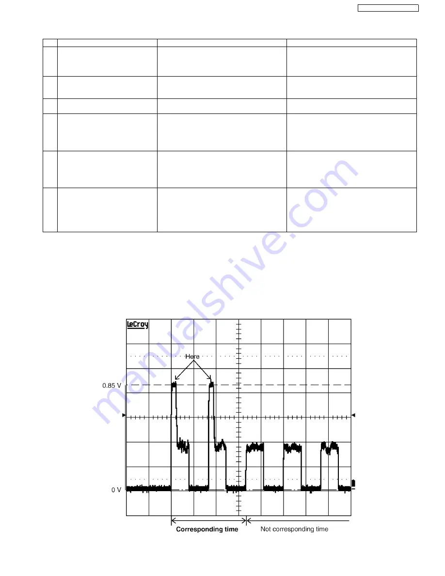
(*5)
Caution for measuring RSSI:
It must be measured RSSI of reception unit when the timing of transmission corresponds to the timing of reception as below.
EX.) RSSI waveform
No.
Item
BU (Base Unit) Check
HS (HandSet) Check
1
Link Confirmation Normal
HS, BU Mode: [Normal mode]
1. Register Regular HS to BU (to be
checked).
2. Press [Talk] key of the Regular HS to
establish link.
1. Register HS (to be checked) to Regular
BU.
2. Press [Talk] key of the HS to establish link.
2
Control signal confirmation
HS, BU Mode: [Burst TX mode]
1. Check BBIC interface. (*2)
1. Check BBIC interface. (*2)
3
X’tal Frequency confirmation
1. Check X’tal Frequency. (*3)
(10.368 MHz ± 100 Hz)
1. Check X’tal Frequency. (*4)
(10.368 MHz ±100Hz)
4
TX Power confirmation (*5)
HS, BU mode
Checked unit: [Burst TX mode] (*1)
Regular unit: [Test RX mode] (*1)
1. Place the Regular HS about 15cm away
from the BU.
2. Confirm that RSSI of the Regular HS is
approximately 0.85 V by Oscilloscope. (*3)
1. Place the HS about 15cm away from the
Regular BU.
2. Confirm that RSSI of the Regular BU is
approximately 0.85 V by Oscilloscope. (*4)
5
RX Sensitivity confirmation (*5)
HS, BU mode
Checked unit: [Test RX mode] (*1)
Regular unit: [Burst TX mode] (*1)
1. Place the Regular HS about 15cm away
from the BU.
2. Confirm that RSSI of the BU is approxi-
mately 0.85 V by Oscilloscope. (*3)
1. Place the HS about 15cm away from the
Regular BU.
2. Confirm that RSSI of the HS is approxi-
mately 0.85 V by Oscilloscope. (*4)
6
Range Confirmation Normal
HS, BU Mode: [Normal mode]
1. Register Regular HS to BU (to be
checked).
2. Press [Talk] key of the Regular HS to
establish link.
3. Compare the range of the BU (being
checked) with that of the Regular BU.
1. Register HS (to be checked) to Regular
BU.
2. Press [Talk] key of the HS to establish link.
3. Compare the range of the HS (being
checked) with that of the Regular HS.
Summary of Contents for KX-TG1032SK
Page 2: ...2 KX TG1032SK KX TGA101S ...
Page 14: ...14 KX TG1032SK KX TGA101S 4 6 Signal Route ...
Page 15: ...15 KX TG1032SK KX TGA101S ...
Page 17: ...17 KX TG1032SK KX TGA101S 8 Service Mode 8 1 Engineering Mode 8 1 1 Base Unit ...
Page 19: ...19 KX TG1032SK KX TGA101S 8 1 2 Handset ...
Page 33: ...33 KX TG1032SK KX TGA101S 9 1 4 5 RF BBIC Interface Signal Wave Form SYCL SYEN SYDA ...
Page 39: ...39 KX TG1032SK KX TGA101S ...
Page 40: ...40 KX TG1032SK KX TGA101S 10 1 2 Handset ...
Page 41: ...41 KX TG1032SK KX TGA101S 10 1 3 Charger Unit ...
Page 42: ...42 KX TG1032SK KX TGA101S ...
Page 43: ...43 KX TG1032SK KX TGA101S 10 2 How to Replace the Handset LCD ...
Page 44: ...44 KX TG1032SK KX TGA101S 10 3 How and Where to fix the spacer ...
Page 45: ...45 KX TG1032SK KX TGA101S ...
Page 65: ...65 KX TG1032SK KX TGA101S Memo ...
Page 72: ...72 KX TG1032SK KX TGA101S Memo ...
Page 78: ...78 KX TG1032SK KX TGA101S 15 3 Cabinet and Electric Parts Charger Unit ...


