background image

51

3

Features

S

• If the system clock is not set by System Programming or if the calendar

IC is out of order, the date and time is not printed out.

• If FLASH Signal is manually sent out during a conversation, the call

record is printed and a new record is started.

Connection References

Section 2, Installation,
2.3.10  Printer Connection   

Programming References

Section 4, System Programming,
[000]  Date and Time Set
[120] Charge Display Selection
[212]  Call Duration Count Start Time 
[800]  SMDR Incoming / Outgoing Call Log Printout
[801]  SMDR Format 
[802]  System Data Printout 
[806]–[807]  EIA (RS-232C) Parameters
[815] SMDR Out put Mode  

Feature References

None

Operation References

Not applicable.

Summary of Contents for KX-TD816CE

Page 1: ...KX TD816CE KX TD1232CE Added and Changed Features for Installation Manual and Programming Tables Please read this manual first and then the Installation Manual In this manual the last letter CE of ea...

Page 2: ...rotect printed circuit boards from static electricity do not touch connectors indicated below To discharge body static touch ground or wear a grounding strap Warning REMOTE SYSTEM INTER CONNECTION DIS...

Page 3: ...Remote Wake Up Call 19 SMDR for Timed Reminder 20 Section 4 System Programming 009 Emergency Dial Number Set 21 010 Budget Management 22 011 Charge Margin Rate 23 120 Charge Display Selection 24 121...

Page 4: ...m Speed Dialing Number Set 44 52 002 System Speed Dialing Name Set 44 54 100 Flexible Numbering 44 109 Expansion Unit Type 45 55 211 Dial Start Time 45 412 Pause Time 45 413 Flash Time 45 601 Class of...

Page 5: ...5 Added Features...

Page 6: ...tallation of Optional Cards and Units 2 ISDN S0 Line Unit Connection To add two ISDN S0 lines use the optional 2 ISDN S0 Line Unit KX TD280 This unit can be installed in any of the expansion areas pro...

Page 7: ...Hook the cabinet to the main unit and slide the cabinet to the left until it is secured Slit Slit 4 Loosen the outside screw and slide the cover to the right D1232 D1232 DIGITAL SUPER HYBRID SYSTEM P...

Page 8: ...so 9 Close the cabinet cover and secure the outside screw 10 Cover the cords with the cord holder included 11 Fix the cords to the wall as shown so that the front cover can be opened Programming Refer...

Page 9: ...the main unit remove them beforehand 2 Attach the Pay Tone Card s KX TD189 to the CO Line Card with the spacers Accessary included One Pay Tone Card for KX TD816 and up to two Pay Tone Cards for KX T...

Page 10: ...esponds to CO1 OPJPB to CO2 OPJPC to CO3 OPJPD to CO4 OPJPE to CO5 OPJPF to CO6 OPJPG to CO7 and OPJPH to CO8 When you install the Pay Tone Card A you will detect the pay tone signal from CO1 CO4 and...

Page 11: ...Call Information in this manual HOTEL APPLICATION in this manual 1 Loosen five screws located on the rear of the 4 CO Line Unit 2 Remove the back plate and take out the P board 3 Attach the Pay Tone...

Page 12: ...HOTEL APPLICATION Operation References Not applicable Calling Line Identification Restriction CLIR Description Allows the extension user to restrict the presentation of the calling party s number to...

Page 13: ...um of 99999 Meter can be collected The existing call is not referred It is programmable to select the first display Meter or Charge by System Programming This can be switched manually at each extensio...

Page 14: ...tored in program 001 and if a match is found decides the caller s name by using the System Speed Dialing Names stored in program 002 The CO line name display has precedence on the Operator s telephone...

Page 15: ...n party answers the call and record it manually When the information area is full i e more than 15 calls the user can control the log mode at his her extension CO Incoming Call Information Log Mode If...

Page 16: ...ed conversion table Explanation 1 An incoming call from the ISDN network reaches your DSHS Digital Super Hybrid System The ISDN network informs DSHS of the DDI number 2 DSHS converts the DDI number to...

Page 17: ...n Electronic Station Lockout A maximum of eight emergency numbers are assignable An extension number can be stored as an emergency number to call service desk with 1 digit for HOTEL APPLICATION 009 Em...

Page 18: ...ot ready cleaned up or not The check out operation by the operator changes the room status from check in to check out not ready mode Changing from check out not ready to check out ready mode can be ex...

Page 19: ...on Operator 1 s extension turns red if the guest does not respond to the alarm ringing The Alert button can also be used to confirm the not responded room number or to call back the room The Alert bu...

Page 20: ...Reminder record Conditions Connect a printer provided with an EIA RS 232C interface to the EIA RS 232C connector located on the main unit Connection References Section 2 Installation 2 3 10 Printer Co...

Page 21: ...y press CLEAR To change the current entry press CLEAR and the new number 5 Press STORE 6 To program another emergency dial number press NEXT or PREV or SELECT and the desired emergency dial location n...

Page 22: ...splay Jack NO 3 Enter a jack number To enter jack number 01 you can also press NEXT Display example 01 1 0 4 Enter a charge limitation To delete the charge limitation press CLEAR 5 Press STORE 6 To pr...

Page 23: ...ming 1 Enter 011 Display Charge Margin 2 Press NEXT Display Margin 0 3 Enter a charge margin rate To delete the charge limitation press CLEAR 4 Press STORE 5 Press END Conditions Telephone charge Real...

Page 24: ...T Display example in Meter 3 Keep pressing SELECT until the desired selection is displayed 4 Press STORE 5 Press END Conditions This programming is only effective when you select for charge SMDR Outpu...

Page 25: ...Denomi KC 3 Enter a 0 9 SELECT CLEAR or none To change the current entry press CLEAR and the new characters To enter characters see Section 4 1 3 Entering Characters 4 Press STORE 5 Press END Conditi...

Page 26: ...splay Jack NO 3 Enter a jack number To enter jack number 01 you can also press NEXT Display example 01 Enable 4 Keep pressing SELECT until the desired selection is displayed 5 Press STORE 6 To program...

Page 27: ...charge information Selection 4 digits 0000 through 9999 Default 1234 Programming 1 Enter 123 Display Charge ID Code 2 Press NEXT Display example Code 1234 3 Enter an ID code To delete the current ent...

Page 28: ...g 1 Enter 124 Display Hotel Apply Asn 2 Press NEXT Display example Hotel Disable 3 Keep pressing SELECT until the desired selection is displayed 4 Press STORE 5 Press END Conditions If Enable is selec...

Page 29: ...07 DSS Console Port and Paired Telephone Assignment 008 Absent Messages 009 Emergency Dial Number Set 010 Budget Management 011 Charge Margin Rate Selection Password 4 through 7 digits Default 1234 Pr...

Page 30: ...gh 64 Default 10 min Programming 1 Enter 216 Display MW Ring Time 2 Press NEXT Display example Interval 10 min 3 Enter the time To change the current entry press CLEAR and enter the new time 4 Press S...

Page 31: ...n Number of times 1 through 5 Default 3 times Programming 1 Enter 217 Display Alarm Times 2 Press NEXT Display example Attempt 3 3 Enter the time To change the current entry press CLEAR and enter the...

Page 32: ...Selection Time seconds 30 through 240 Default 60 sec Programming 1 Enter 218 Display Alarm Interval 2 Press NEXT Display example Interval 60 sec 3 Enter the time To change the current entry press CLEA...

Page 33: ...er a name For entering characters see Section 4 1 3 Entering Characters To delete the current entry press CLEAR To change the current entry press CLEAR and enter the new name 5 Press STORE 6 To progra...

Page 34: ...NEXT Display example CO09 Not Stored 4 Enter the telephone number To delete the current entry press CLEAR To change the current entry press CLEAR and the new number 5 Press STORE 6 To program another...

Page 35: ...you can also press NEXT Display example CO09 Enable 4 Keep pressing SELECT until the desired selection is displayed 5 Press STORE 6 To program another CO line press NEXT or PREV or SELECT and the desi...

Page 36: ...X TD1232 you can also press NEXT Display example CO09 Disable 4 Keep pressing SELECT until the desired selection is displayed 5 Press STORE 6 To program another CO line press NEXT or PREV or SELECT an...

Page 37: ...Keep pressing SELECT until the desired selection is displayed 5 Press STORE 6 To program another CO line press NEXT or PREV or SELECT and the desired CO line number 7 Repeat steps 4 through 6 8 Press...

Page 38: ...ess NEXT To select the second part 2 press NEXT after entering a jack number Display 01 1 001 4 Enter a DDI number To delete the current entry press CLEAR 5 Press STORE 6 To program another jack press...

Page 39: ...DDI Number 1 through 6 digits Default All floating stations Not stored Programming 1 Enter 611 Display F EXT DDI NO 2 Press NEXT to program the operator Display Operator 3 Enter a DDI number To delete...

Page 40: ...815 Display SMDR Output Mode 2 Press NEXT Display example SMDR Regular 3 Keep pressing SELECT until the desired selection is displayed 4 Press STORE 5 Press END Conditions Select the Output Mode used...

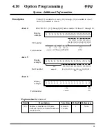
Page 41: ...se feedback tone when a dialed number is sent to the line 0 disable 1 enable 1 None Explanation for Area 4 Area 6 Display example 1111111111111111 Field number unused 35 Area 4 KX TD1232 17 through 24...

Page 42: ...for Timed Reminder when it starts and it is not answered 0 By call 1 Permanent 0 By call 1 Permanent 0 Fix 0 1 Automatic 0 DIL 1 N 1 Operator 0 DIL 1 N 1 Operator 0 Disable 1 Enable 0 whole number 1 o...

Page 43: ...43 Changed Features...

Page 44: ...ected to a DSS Console is programmed as a XDP jack a SLT can be connected to the port in parallel 001 System Speed Dialing Number Set Section 4 Section 4 002 System Speed Dialing Name Set These progra...

Page 45: ...d with a new one For detail refer to page 57 109 Expansion Unit Type Section 4 This program has been replaced with a new one For details refer to page 55 412 Pause Time Section 4 Default All CO line g...

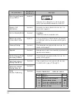
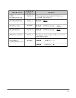
Page 46: ...Charge Meter This is shown during an established call A display example CO01 00005 Charge Fee This is shown during an established call A display example CO01 00001 15KC Call duration This is shown du...

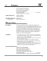
Page 47: ...red in the mailbox of a Voice Processing System Conditions For a proprietary telephone which is not provided with a MESSAGE button a flexible CO button can be assigned as the MESSAGE button either by...

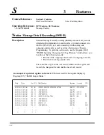
Page 48: ...tgoing outside calls or outgoing toll calls Record of incoming outside calls There are three types of the call record which are the regular call record the charge call record and the meter call record...

Page 49: ...00 00KC 06 24 96 10 11AM 280 22 0924312111 00 03 02 00128 00KC D1 06 24 96 10 20AM 120 13 I 00 21 46 00000 00KC 1 2 3 4 5 6 7 8 9 An example of a printed meter call record When selected for charge by...

Page 50: ...ndition Code shows call handling type with the following codes TR Transfer FW Call Forwarding to CO Line D0 Non Security CO Line Access using DISA D1 through D4 DISA User Codes 1 through 4 RM Remote a...

Page 51: ...a new record is started Connection References Section 2 Installation 2 3 10 Printer Connection Programming References Section 4 System Programming 000 Date and Time Set 120 Charge Display Selection 2...

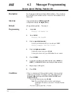
Page 52: ...ay example 000 Not Stored 4 Enter a telephone number To delete the current entry press CLEAR To change the current entry press CLEAR and the new number 5 Press STORE 6 To program another speed dial nu...

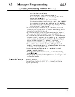
Page 53: ...code before the line access code Refer to Section 3 Account Code Entry If you are storing a number for CO Incoming Call Information Display with name enter hyphen after the line access code The syste...

Page 54: ...ess NEXT Display example 000 Not Stored 4 Enter a name For entering characters see Section 4 1 3 Entering Characters To delete the current entry press CLEAR To change the current entry press CLEAR and...

Page 55: ...Enter 109 Display Expansion Card 2 Press NEXT Display example C E 3 Keep pressing SELECT until the desired selection is displayed 4 Press 5 Keep pressing SELECT until the desired selection is displaye...

Page 56: ...re three expansion areas in each system for KX TD1232 areas 1 2 and 3 from bottom to top Up to two 8 Station Line Units and either one 4 CO Line Unit or 2 ISDN S0 Line Unit can be installed in each sy...

Page 57: ...Assign 2 Press NEXT Display Jack NO 3 Enter a jack number To enter jack number 01 you can also press NEXT To select the second part 2 press NEXT after entering a jack number Display example 01 1 COS1...

Page 58: ...aster System and 33 through 64 are for the Slave if available Jack numbers in the out of service system are unacceptable For an explanation of jack numbering see Rotation of jack number on page 4 7 To...

Page 59: ...ection Incoming Set 415 CPC Signal Detection Outgoing Set 4 5 CO Line Programming 110 Caller ID Code Set 111 Caller ID Name Set 406 Caller ID Assignment 4 3 System Programming 4 3 System Programming C...

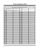
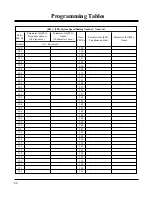
Page 60: ...022 023 024 025 026 027 028 029 030 031 032 033 034 035 Parameter for 001 Telephone number 24 digits max Parameter for 002 Name 10 characters max Item SPD No 036 037 038 039 040 041 042 043 044 045 04...

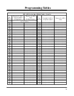
Page 61: ...094 095 096 097 098 099 100 101 102 103 104 105 106 107 Parameter for 001 Telephone number 24 digits max Parameter for 002 Name 10 characters max Item SPD No 108 109 110 111 112 113 114 115 116 117 11...

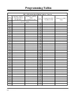
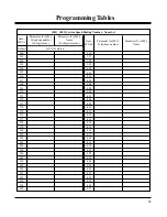
Page 62: ...166 167 168 169 170 171 172 173 174 175 176 177 178 179 Parameter for 001 Telephone number 24 digits max Parameter for 002 Name 10 characters max Item SPD No 180 181 182 183 184 185 186 187 188 189 19...

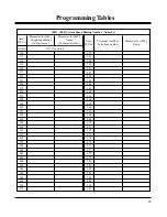
Page 63: ...238 239 240 241 242 243 244 245 246 247 248 249 250 251 Parameter for 001 Telephone number 24 digits max Parameter for 002 Name 10 characters max Item SPD No 252 253 254 255 256 257 258 259 260 261 26...

Page 64: ...310 311 312 313 314 315 316 317 318 319 320 321 322 323 Parameter for 001 Telephone number 24 digits max Parameter for 002 Name 10 characters max Item SPD No 324 325 326 327 328 329 330 331 332 333 33...

Page 65: ...382 383 384 385 386 387 388 389 390 391 392 393 394 395 Parameter for 001 Telephone number 24 digits max Parameter for 002 Name 10 characters max Item SPD No 396 397 398 399 400 401 402 403 404 405 40...

Page 66: ...452 453 454 455 456 457 458 459 460 461 462 463 464 465 Parameter for 001 Telephone number 24 digits max Parameter for 002 Name 10 characters max Item SPD No 466 467 468 469 470 471 472 473 474 475 47...

Page 67: ...12 2 13 1 13 2 14 1 14 2 15 1 15 2 16 1 16 2 17 1 17 2 18 1 18 2 19 1 19 2 20 1 20 2 21 1 21 2 22 1 22 2 23 1 23 2 24 1 24 2 25 1 25 2 26 1 26 2 27 1 27 2 28 1 28 2 29 1 29 2 30 1 30 2 31 1 31 2 32 1...

Page 68: ...ture Default Parameter 54 55 56 57 58 59 60 61 62 63 64 65 66 Reserved Emergency dial number 1 Emergency dial number 2 Emergency dial number 3 Emergency dial number 4 Emergency dial number 5 Emergency...

Page 69: ...51 52 53 54 55 56 57 58 59 60 61 62 63 64 Parameter 4 7 digits consisting of 0 9 125 User Password Default 1 2 3 4 124 Hotel Application in Meter in Charge Default Selection 123 Charge Verification I...

Page 70: ...Item CO Line No Parameter Name 10 characters max Not Stored Selection Enable Disable Parameter Telephone No 16 digits max Not Stored Selection Enable Disable Selection Enable Disable Default all all C...

Page 71: ...1 19 2 20 1 20 2 21 1 21 2 22 1 22 2 23 1 23 2 24 1 24 2 25 1 25 2 26 1 26 2 27 1 27 2 28 1 28 2 29 1 29 2 30 1 30 2 31 1 31 2 32 1 32 2 33 1 33 2 34 1 34 2 35 1 35 2 36 1 36 2 37 1 37 2 38 1 38 2 39...

Page 72: ...2 22 1 22 2 23 1 23 2 24 1 24 2 25 1 25 2 26 1 26 2 27 1 27 2 28 1 28 2 29 1 29 2 30 1 30 2 31 1 31 2 32 1 32 2 33 1 33 2 34 1 34 2 35 1 35 2 36 1 36 2 37 1 37 2 38 1 38 2 39 1 39 2 40 1 40 2 41 1 41...

Page 73: ...put Mode Regular Charge Default Selection Item Floating Station Operator Pager 1 Pager 2 Pager 3 Pager 4 DISA 1 DISA 2 MODEM 611 ISDN DDI Number Floating Number Transformation Parameter DDI No 1 6 dig...

Page 74: ...t at a time 0 0 sec 1 5 sec 0 disable 1 enable Field 23 17 23 18 23 23 23 24 24 25 27 28 29 30 31 32 33 34 35 36 Field Default Selection AREA 04 Fields 23 17 through 23 24 24 25 and 27 0 0 1 1 0 0 0 0...

Page 75: ......

Page 76: ...Printed in Japan PSQX1168ZA S0796MT0 CE Matsushita Electric of Industrial Co Ltd Central P O Box 288 Osaka 530 91 Japan...

Reviews: