General Installation
Installation Manual
51
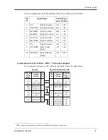
The pin configuration of Serial Interface (RS-232C) Connector is as follows:
Connection Chart for Printer / IBM
*1
Personal Computer
If you connect a printer or a PC with a 25-pin cable, follow the chart below.
Pin
No.
Signal Name
Circuit Type
EIA CCITT
1
2
FG
SD (TXD)
Frame Ground
Transmitted Data
AA
BA
101
103
3
4
RD (RXD)
RS (RTS)
Received Data
Request To Send
BB
CA
104
105
5
6
CS (CTS)
DR (DSR)
Clear To Send
Data Set Ready
CB
CC
106
107
7
8
SG
CD (DCD)
Signal Ground
Data Carrier
Detect
AB
CF
102
109
20
ER (DTR)
Data Terminal
Ready
CD
108.2
*1
IBM is a registered trademark of International Business Machines Corporation.
®
Circuit
Type
(EIA)
Signal
Name
Pin
No.
AA
BA
FG
SD (TXD)
RD (RXD)
CS (CTS)
CR (DSR)
SG
ER (DTR)
Signal
Name
FG
RD (RXD)
SD (TXD)
ER (DTR)
SG
CS (CTS)
CR (DSR)
CD (DCD)
1
2
3
5
6
7
20
Pin
No.
1
3
2
20
7
5
6
8
BB
CB
CC
AB
CD
Circuit
Type
(EIA)
AA
BB
BA
CD
AB
CB
CC
CF
System
25-pin Cable Printer/PC
Summary of Contents for KX-T7020
Page 14: ...Table of Contents 14 Installation Manual ...
Page 26: ...System Outline 26 Installation Manual ...
Page 27: ...General Installation Installation Manual 27 Section 2 General Installation ...
Page 86: ...General Installation 86 Installation Manual ...
Page 94: ...Troubleshooting 94 Installation Manual ...
Page 95: ...Index 95 Section 4 Index ...
Page 97: ...Index 97 W Wall Mounting 32 ...
Page 98: ...Index 98 ...
Page 99: ...Index 99 ...


