background image

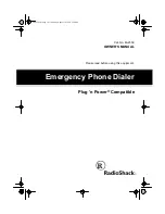
17.2. Ethernet/Power block

KX-NT265X/KX-NT265X-B

  Ethernet/POWER block

0.1u/250V

C141

1000P/2kV

C137

DG

DG

C144

C134

NC

R114

NC

D3

NC

D3.3V

DC_ALARM

C138

0.1u/250V

C136

1000P/2kV

C142

PHY_nRST

M1_COL

M1_TXD[3-0]

M1_TXEN

M1_MDIO

M1_RXCLK

M1_CRS

M1_RXDV

M1_TXCLK

M1_RXER

M1_RXD[3-0]

M1_MDC

L113

L111

L110

L108

R131

75

R127

75

R130

75

R126

75

R110

49.9(1%)

C109 27p

C110

27p

X2

25MHz

R105

33

R122

68.1(1%)

R118

100k

(1/4W)

C146

100u/6.3V

C147

100u/6.3V

IC6

#TRPBF

1

NC1

2

RCLASS

3

NC3

4

VIN

5

VOUT

6

RWRGD

7

NC7

8

GND

R101

39

DG

DG

R108

6.49k(1%)

R100

1k

R111

49.9(1%)

R112
49.9(1%)

R113

49.9(1%)

RA100

39

R107

33

D1.8V

D11

1

23

4

D13

1

23

4

C145

10u/100V

C129

2.2u/100V

C122
K0.022u

C115

100u/6.3V

DG

C128

0.1u/250V

R117
100k

L103

100uH

C120

K0.022u

R116

10k

DG

DG

DG

DG

DG

DG

DG

DG

PHY2.5V

PHY2.5V

PHY2.5V

PHY2.5V

0

L101

PHY2.5V

C118

K0.1u

C119

K0.1u

C111

Z22u

DG

PHY2.5V

0

L102

PHY_nPD

DG

D1

4.7V

R106

100(1/4W)

IP1
250mA

R103

10k

R102

10k

R115

10k

IC10

1

CE

2

GND

3

NC

4

VDD

5

VOUT

C105

Z10u

C104

Z10u

AG_2

AG_2

DG

D8

100V/3A

D7

40V/2A

D6
40V/2A

DG

DG

DG

DG

DG

DG

DG

DG

DG

DG

DG

DG

DG

DG

D5.0V

D3.3V

PHY3.3V

0

L100

PHY3.3V

PHY3.3V

PHY3.3V

L105

L106

0

PHY_nIRQ

D5.0V

D1.8V

D3.3V

nDETPDN

PHY2.5V

DG

R109 1

D4

D5

100V/3A

D2

IC2

1

MDIO

2

MDC

3

RXD3/PHYAD1

4

RXD2/PHYAD2

5

RXD1/PHYAD3

6

RXD0/PHYAD4

7

VDDIO7

8

GND8

9

RXDV/PCS_LPBK

10 RXC

11 RXER/ISO

12 GND12

13

VDDC

14

TXER

15

TXC/REF_CLK

16

TXEN

17

TXD0

18

TXD1

19

TXD2

20

TXD3

21

COL/RMII

22

CRS/RMII_BTB

23

GND23

24

VDDIO24

25

INT#/PHYAD0

26

LED0/TEST

27

LED1/SPD100

28

LED2/DUPLEX

29

LED3/NWAYEN

30

PD#

31

VDDRX

32

RX-

33

RX+

34

FXSD/FXEN

35

GND35

36

GND36

37

REXT

38

VDDRCV

39

GND39

40

TX-

41

TX+

42

VDDTX

43

GND43

44

GND44

45

X0

46

X1

47

VDDPLL

48

RST#

IC9

1

VIN

2

VSS

3

CE

4

NC

5

VOUT

T1

TD+

1

TCT

2

TD-

3

NC4

4

NC5

5

RD+

6

RCT

7

RD-

8

RX- 9

RXCT 10

RX+ 11

NC12 12

NC13 13

TX- 14

TXCT 15

TX+ 16

IC5

1

NC1

2

SW

3

BST

4

ISEN

5

SGND

6

RTN

7

NC7

8

NC8

9

FB

10

SS

11

RON/SD

12

VCC

13

VIN

14

NC14

R135

39

R136

33

R137

33

D3.3V

DG

AG

DG

A3.3V

D5.0V_1

D5.0V_1

C148

0.7F/2.5V

C149

0.7F/2.5V

C113 Z0.1u

C418

Z0.1u

C414

Z0.1u

C416

Z0.1u

C401

Z0.1u

C420

Z0.1u

C415

Z0.1u

C407

Z0.1u

C131

K0.01u

C402

Z0.1u

K0.01u

C132

C417

Z0.1u

C102

Z0.1u

C419

Z0.1u

C413

Z0.1u

C410

Z0.1u

C404

NC

C403

Z0.1u

C411

Z0.1u

C408

Z0.1u

C409

Z0.1u

C406

Z0.1u

C405

Z0.1u

C412

Z0.1u

C116

Z0.1u

C121

K0.01u

C108

K0.01u

K0.01u

C100

K0.01u

C154

K0.01u

C112

K0.01u

C101

Z0.1u

C106

Z0.1u
C130

C133
Z0.1u

C114

NC

C421

Z0.1u

C422

Z0.1u

C423

Z0.1u

C424

Z0.1u

C425

Z0.1u

C426

Z0.1u

C427

Z0.1u

C428

Z0.1u

C139

NC

0.047u/100V

C140

C143 NC

JK4

1

2

3

R120

0

R119

0

R133

0

R134

0

C430

Z0.1u

C431

Z0.1u

C432

Z0.1u

C433

Z0.1u

C434

Z0.1u

C435

Z0.1u

C437

Z0.1u

D3.3V_2

C150

100u/6.3V

DG

DG

DG

R138

1M

R139

120

R140

R141

R142

R143

C151

Z0.1u

C152

Z0.1u

DG

DG

C438

Z0.1u

C439

Z0.1u

C440

Z0.1u

C436

Z0.1u

D1.8V

DG

C441

Z0.1u

JK1

1

TX+

2

TX-

3

RX+

4

4

5

5

6

RX-

7

7

8

8

DCIN+

DCIN-

PoE+

PoE-

L114

L115

L116

L117

L118

C123
Z0.1u

C135

Z0.1u

C117

NC

L213

IC8

Vout

1

Vin

2

NC

3

Vss

4

C442

Z0.1u

DG

AG

C443

Z0.1u

C107

NC

C103

Z0.1u

C153

NC

M1_TXD[0]

M1_TXD[1]

M1_TXD[2]

M1_TXD[3]

M1_RXD[0]

M1_RXD[1]

M1_RXD[3]

M1_RXD[2]

DC_JACK

EtherJACK
(LAN)

8.5   POWER  SUPPLY  CIRCUIT

8.4   Ethernet   CIRCUIT

(5)

(7)

(6)

(10)

(11),(12)

(11),(12)

(8),(9)

(8),(9)

KX

-N

T

265

X
/

KX

-NT

265X

-B

46

Summary of Contents for KX-NT265X

Page 1: ... IMPORTANT INFORMATION ABOUT LEAD FREE PbF SOLDERING If lead free solder was used in the manufacture of this product the printed circuit boards will be marked PbF Standard leaded Pb solder can be used as usual on boards without the PbF mark When this mark does appear please read and follow the special instructions described in this manual on the use of PbF and how it might be permissible to use Pb...

Page 2: ...net PORT 25 9 7 LED DOES NOT LIGHT 26 10 IC DATA 28 10 1 IC1 VoIP 28 10 2 IC2 Ethernet 32 10 3 IC5 DC DC Convertor 33 10 4 IC6 PoE Interface Controller 34 11 TERMINAL GUIDE OF ICs TRANSISTORS AND DIODES 35 12 HOW TO REPLACE A FLAT PACKAGE IC 36 12 1 PREPARATION 36 12 2 REMOVAL PROCEDURE 36 12 3 INSTALLATION PROCEDURE 36 12 4 REMOVING SOLDER FROM BETWEEN PINS 36 13 CABINET AND ELECTRICAL PARTS LOCA...

Page 3: ...temperature soldering irons Do not heat the PCB for too long time in order to prevent solder splash or damage to the PCB PbF solder will tend to splash if it is heated much higher than its melting point approximately 1100 F 600 C When applying PbF solder to double layered boards please check the component side for excess which may flow onto the opposite side See figure below 1 1 SUGGESTED PbF SOLD...

Page 4: ...TECHNICIANS ICs and LSIs are vulnerable to static electricity When repairing the following precautions will help prevent recurring malfunctions 1 Cover the plastic parts boxes with aluminum foil 2 Ground the soldering irons 3 Use a conductive mat on the worktable 4 Do not touch IC or LSI pins with bare fingers 4 KX NT265X KX NT265X B ...

Page 5: ...3 SPECIFICATIONS Design and specifications are subject to change without notice 5 KX NT265X KX NT265X B ...

Page 6: ...4 LOCATION OF CONTROLS Note For further information refer to the User Manual of the Hybrid IP PBX 6 KX NT265X KX NT265X B ...

Page 7: ...V1E for Hong Kong Singapore and Malaysia KX A237AL AC adaptor PQLV1AL for Oceania KX A237AG AC adaptor PQLV1AG for Argentina KX A237BR AC adaptor PQLV1LB for Brazil 5 CONNECTION CAUTION The AC adaptor is used as the main disconnect device Ensure that the AC outlet is located near the unit and is easily accessible Notes Consult your dealer for more details about the AC adaptor 7 KX NT265X KX NT265X...

Page 8: ...TRUCTIONS 1 Remove the Stand 2 Remove 5 Screws 3 Remove the Cabinet Cover 4 Remove the Connector from the Main Board 5 Remove 2 Screws A 6 Remove the Main Board and the LCD from the Cabinet Body 8 KX NT265X KX NT265X B ...

Page 9: ...7 Remove the Flat Cable from the Main Board 8 Remove the LCD Holder by sliding the Hook in the direction of the arrow from the Main Board 9 KX NT265X KX NT265X B ...

Page 10: ...GPIO GPIO GPIO SIO GPIO GPIO GPIO GPIO Headset X1 for LCD for DSP nRST PHY TX_EN MIC SW Mute SP2 Mute SP1 HSIN HSOUT MICIN SPOUT Mute SP0 TX_ER TX_CLK RX_CLK RX_DV RX_ER RXD 3 0 TXD 3 0 CRS COL Handset KEY LED LCD Analog I F Power I F KEY LED Dynamic Matrix 16 x 1 5 0V to IC 4 5V 3 3V 1 8V CAP MHz PHY D5V LCD_SCK LCD_DATA LCD_STB LCD_CONT1 LCD_CONT2 KEYIN 5 0 KEYOUT 5 0 CO 8 3 R CO 8 3 G CO 2 1 R ...

Page 11: ...ation but there is no problem on the LCD then the failure of the CPU system memory IC3 and IC4 should be considered too 8 2 LCD CIRCUIT LCD data are outputted from pin138 of IC1 to LCD module IC12 is a converter circuit which outputs the voltage 5V necessary for LCD driving LCD contrast is set by electronic volume in the LCD module KX NT265 uses a 16 characters x 1 line LCD 8 3 RESET CIRCUIT Reset...

Page 12: ...ernet port JK1 through a transformer and so is isolated Also Ethernet port JK1 gets power from the Ethernet line for PoE Power over Ethernet as shown below It is connected between IC2 and the VoIP IC1 by high speed bus called MII Management Independent Interface bus operating with 25MHz 12 KX NT265X KX NT265X B ...

Page 13: ... corresponding current and is identified on the hub side sothat the hub starts to supply 48V In that case as there is OR with the power from Ethernet port JK1 and the power from DC jack JK4 by D4 and D5 the power from Ethernet port is supplied to the switching regulator IC5 preferentially 2 Switching Regulator Circuit This switches the power from the DC jack or Ethernet port by IC5 to generate 5 0...

Page 14: ...KX NT265X KX NT265X B 14 ...

Page 15: ...adjustment by a built in DSP of IC1 then sent to PBX Transmitting signal inputted from headset microphone is controlled by transmission switching SW IC16 as follows IC16 pin5 H Headset Call IC16 pin5 L Handset Call Receiving signal inputted from PBX Gain adjustment by a built in DSP of IC1 D A conversion and outputted from IC1 pin115 Amplified by IC17 and IC19 and outputted to headset 3 Speakerpho...

Page 16: ...utted into KEYIN 5 0 when the key is pressed 8 8 LED CIRCUIT The lighting of the LED is controlled by IC1 The LEDs light up in a static lighting system Controlled by I O ports of IC1 LED1 INTERCOM LED2 AUTOANSWER LED3 AUTODIAL LED4 MESSAGE LED5 SP PHONE LED12 CO2 LED13 CO1 Controlled by serial I F of IC13 LED 6 11 CO 8 3 16 KX NT265X KX NT265X B ...

Page 17: ...17 KX NT265X KX NT265X B ...

Page 18: ...9 TROUBLESHOOTING GUIDE 9 1 NO OPERATION 18 KX NT265X KX NT265X B ...

Page 19: ... Note Refer to waveform 1 3 and 6 in 17 4 WAVEFORM P 48 19 KX NT265X KX NT265X B ...

Page 20: ...20 KX NT265X KX NT265X B ...

Page 21: ...9 2 LCD DOES NOT OPERATE Note Refer to waveform 4 in 17 4 WAVEFORM P 48 21 KX NT265X KX NT265X B ...

Page 22: ...9 3 HANDSET DOES NOT WORK Receive Send 22 KX NT265X KX NT265X B ...

Page 23: ...9 4 HEADSET DOES NOT WORK Receive Send 23 KX NT265X KX NT265X B ...

Page 24: ...9 5 SPEAKER PHONE DOES NOT WORK Receive Send 24 KX NT265X KX NT265X B ...

Page 25: ...9 6 Ethernet DOES NOT WORK Ethernet PORT Note Refer to waveform 7 12 in 17 4 WAVEFORM P 48 25 KX NT265X KX NT265X B ...

Page 26: ...9 7 LED DOES NOT LIGHT Note Refer to waveform 13 in 17 4 WAVEFORM P 48 26 KX NT265X KX NT265X B ...

Page 27: ... LED GREEN MODE LED TEST 3 Press Dial 4 LCD displays NNNNNNNNNNNNNNNN All Red LEDs lit 4 Press Dial 5 LCD displays I I I I I I I I I I I I I I I I All Green LEDs lit 5 Press Dial 6 LCD displays BBBBBBBBBBBBBBBB All LEDs go Off KEY TEST 6 Press each keys except dial 12 keys LCD display each KEY name Quit TEST mode Disconnect and connect AC adaptor or Disconnect and connect Ethernet cable 27 KX NT26...

Page 28: ...ess bus 13 NC No internal connection 14 TEST3 I Test pin 15 TEST2 I Test pin 16 TEST1 I Test pin 17 NC No internal connection 18 PVDD18 PLL power supply 1 8V 19 PGND PLL ground 20 VCNT1 O PLL1 VCO control 1 8V 21 WAITn PB12 I O External wait signal or I O port 22 RSTOUTn O Watchdog timer reset output 23 TEST0 I Test pin 24 ROMBUSW I Memory bus width selection 25 A4 O Address bus 26 A3 O Address bu...

Page 29: ...or 62 M1_RXD3 I MAC1 receive data 63 M1_RXD2 I MAC1 receive data 64 M1_RXD1 I MAC1 receive data 65 M1_RXD0 I MAC1 receive data 66 M1_CRS I MAC1 carrier sense 67 M1_COL I MAC1 collision detection 68 M1_MDC O MAC1 MII control clock 69 M1_MDIO I O MAC1 MII control data 70 NC No internal connection 71 M2_TXEN O MAC2 transmit enable 72 DVDD33 Digital system power supply 3 3V 73 DGND Digital system grou...

Page 30: ... port 129 DBG6 PA6 I O Debugging data output or I O port 130 DBG5 PA5 I O Debugging data output or I O port 131 DGB4 PA4 I O Debugging data output or I O port 132 DBG3 PA3 I O Debugging data output or I O port 133 DGB2 PA2 I O Debugging data output or I O port 134 DBG1 PA1 I O Debugging data output or I O port 135 DBG0 PA0 I O Debugging data output or I O port 136 SCK PC15 I O SIO serial clock or ...

Page 31: ...s 192 D5 I O Data bus 193 D4 I O Data bus 194 D3 I O Data bus 195 D2 I O Data bus 196 D1 I O Data bus 197 D0 I O Data bus 198 DVDD18 Digital system power supply 1 8V 199 DGND Digital system ground 200 CTSn1 PC4 I O USART1 clear to send signal or I O port 201 DSRn1 PC5 I O USART1 data set ready signal or I O port 202 RTSn1 PC11 I O USART1 request to send signal or I O port 203 DTRn1 PC12 I O USART1...

Page 32: ...ly power supply 14 TXER I MII Transmit Error Input 15 TXC REFCLK I O MII Transmit Clock Output 16 TXEN I MII Transmit Enable Input 17 TXD0 I MII Transmit Data Input 18 TXD1 I MII Transmit Data Input 19 TXD2 I MII Transmit Data Input 20 TXD3 I MII Transmit Data Input 21 COL RMII O MII Collision Detect Output 22 CRS RMII_BTB O MII Carrier Sense Output 23 GND Ground 24 VDDIO Digital IO 2 5 3 3V toler...

Page 33: ...supply 48 RST I Chip Reset 10 3 IC5 DC DC Convertor Pin No Terminal Name I O Setting Contents of Control Remark 1 NC No internal connection 2 SW O Switching Node 3 BST I Boost pin for bootstrap capacitor 4 ISEN I Current sense 5 SGND Sense Ground 6 RTN I Circuit Ground 7 NC No internal connection 8 NC No internal connection 9 FB I Feedback input from the regulated output 10 SS I Soft start 11 RON ...

Page 34: ... input current VOUT is high impedance until the input voltage rises above the turn on UVLO threshold The output is then current limited See Applications Information 6 nPWRGD O Power Good Output Open Drain Signals to the PD load that the LTC4257 1 MOSFET is on and that the PD s DC DC converter can start operation Low impedance indicates power is good PWRGD is high impedance during detection classif...

Page 35: ...11 TERMINAL GUIDE OF ICs TRANSISTORS AND DIODES 35 KX NT265X KX NT265X B ...

Page 36: ...ith some tools like a soldering wire If some solder is left at the joint on the board the new IC will not be attached properly 12 3 INSTALLATION PROCEDURE 1 Tack the flat pack IC to the PCB by temporarily soldering two diagonally opposite pins in the correct positions on the PCB Be certain each pin is located over the correct pad on the PCB 2 Apply flux to all of the pins on the IC 3 Being careful...

Page 37: ...13 CABINET AND ELECTRICAL PARTS LOCATION 37 KX NT265X KX NT265X B ...

Page 38: ...14 ACCESSORIES AND PACKING MATERIALS 38 KX NT265X KX NT265X B ...

Page 39: ...D LENS ABS HB 7 PQAS57P03Z SPEAKER 8 PSJS02P15Z CONNECTOR 2 PIN 9 PSUS1026Z TORSION SPRING 10 PSBH1010Z1 PUSH BUTTON HOOK for KX NT265X PC ABS HB 10 PSBH1010Z3 PUSH BUTTON HOOK for KX NT265E B PC ABS HB 11 PSHG1271Z RUBBER PARTS MIC COVER 12 L0CBAB000099 BUILTIN MICROPHONE 13 PSJS02Q35Y CONNECTOR 2 PIN 14 PSBX1116Z1 PUSH BUTTON FUNCTION for KX NT265X S ABS HB 14 PSBX1116Z2 PUSH BUTTON FUNCTION for...

Page 40: ... 1 S C2 ECUV1E104ZFV 0 1 S C4 F1G1C104A083 0 1 C5 ECUV1E104ZFV 0 1 S C6 F1G1C104A083 0 1 C7 ECUV1E104ZFV 0 1 S C8 F1G1C104A083 0 1 Ref No Part No Part Name Description Remarks C9 F1G1C104A083 0 1 C10 ECJ1VC1H180J 18P C11 ECJ1VC1H180J 18P C12 ECUV1A105ZFV 1 S C13 F1G1H101A566 100 C14 ECJ1VF1C224Z 0 22 C15 F1G1C1030008 0 01 C16 F1G1C1030008 0 01 C17 F1G1C104A083 0 1 C18 F1G1C104A083 0 1 C19 F1G1C104...

Page 41: ...0 1 C407 F1G1C104A083 0 1 C408 F1G1C104A083 0 1 Ref No Part No Part Name Description Remarks C409 F1G1C104A083 0 1 C410 F1G1C104A083 0 1 C411 F1G1C104A083 0 1 C412 F1G1C104A083 0 1 C413 F1G1C104A083 0 1 C414 F1G1C104A083 0 1 C415 F1G1C104A083 0 1 C416 F1G1C104A083 0 1 C417 F1G1C104A083 0 1 C418 F1G1C104A083 0 1 C419 F1G1C104A083 0 1 C420 F1G1C104A083 0 1 C421 F1G1C104A083 0 1 C422 F1G1C104A083 0 1...

Page 42: ...0 0 R11 ERJ3GEYJ472 4 7K R12 ERJ3GEYJ151 150 R13 ERJ3GEYJ105 1M R14 ERJ3GEY0R00 0 Ref No Part No Part Name Description Remarks R15 ERJ3GEYJ330 33 R16 ERJ3GEYJ103 10K R17 ERJ3GEYJ103 10K R18 ERJ3GEYJ330 33 R19 ERJ3GEYJ103 10K R21 ERJ3GEYJ330 33 R23 ERJ3GEYJ330 33 R24 ERJ3GEYJ330 33 R25 ERJ3GEYJ103 10K R27 ERJ3GEYJ103 10K R28 ERJ3GEYJ103 10K R34 ERJ3GEYJ103 10K R35 ERJ3GEY0R00 0 R36 ERJ3GEYJ151 150 ...

Page 43: ...ion Remarks R248 ERJ3GEYJ151 150 R249 ERJ3GEYJ101 100 R250 ERJ3GEYJ101 100 R251 ERJ3GEYJ151 150 R252 ERJ3GEYJ151 150 R253 D0GB272JA057 2 7K R256 ERJ3GEY0R00 0 15 4 OPTION Ref No Part No Part Name Description Remarks PQLV1 OPTIONAL AC ADAPTOR for Canada and other 100V areas PQLV1CE OPTIONAL AC ADAPTOR for Russia Eastern Europe and other 200V areas PQLV1E OPTIONAL AC ADAPTOR for Hong Kong Singapore ...

Page 44: ...7 DQ20 38 VSSQ38 39 DQ21 40 DQ22 41 VCCQ41 42 DQ23 43 VCC43 1 VCC1 2 DQ0 3 VCCQ3 4 DQ1 5 DQ2 6 VSSQ6 7 DQ3 8 DQ4 9 VCCQ9 10 DQ5 11 DQ6 12 VSSQ12 13 DQ7 14 NC14 15 VCC15 16 DQM0 bit7 0 17 WE 18 CAS 19 RAS 20 CS 21 NC21 22 A12 BA0 45 DQ24 46 VSSQ46 47 DQ25 48 DQ26 49 VCCQ49 50 DQ27 51 DQ28 52 VSSQ52 53 DQ29 54 DQ30 55 VCCQ55 56 DQ31 57 NC57 58 VSS58 59 DQM3 bit31 24 60 A3 61 A4 62 A5 63 A6 64 A7 65 ...

Page 45: ...90 DVDD1 8_90 91 DGND91 92 BIGEND 93 DIVCK PB11 94 PCMIN PB10 95 PCMCLK PB9 96 PCMSYNC1 PB8 97 PCMSYNC2 PB7 98 PCMOUT PB6 99 XDACK PB5 100 DSOD PB4 101 DWR PB3 102 DCK PB2 103 DSL PB1 104 DSID PB0 105 DBG15 PA15 106 DBG14 PA14 107 DBG13 PA13 108 DVDD3 3_108 109 DGND109 110 AVDD3 3_110 111 AGND111 112 HSIN 113 MICIN 114 VREF 115 HSOUT 116 SPOUT 117 AVDD3 3_117 118 AGND118 119 NC119 120 DBG12 PA12 1...

Page 46: ... SPD100 28 LED2 DUPLEX 29 LED3 NWAYEN 30 PD 31 VDDRX 32 RX 33 RX 34 FXSD FXEN 35 GND35 36 GND36 37 REXT 38 VDDRCV 39 GND39 40 TX 41 TX 42 VDDTX 43 GND43 44 GND44 45 X0 46 X1 47 VDDPLL 48 RST IC9 1 VIN 2 VSS 3 CE 4 NC 5 VOUT T1 TD 1 TCT 2 TD 3 NC4 4 NC5 5 RD 6 RCT 7 RD 8 RX 9 RXCT 10 RX 11 NC12 12 NC13 13 TX 14 TXCT 15 TX 16 IC5 1 NC1 2 SW 3 BST 4 ISEN 5 SGND 6 RTN 7 NC7 8 NC8 9 FB 10 SS 11 RON SD ...

Page 47: ... A3 3V A3 3V A3 3V A3 3V A3 3V C210 NC A3 3V R213 10k R212 10k R211 10k AG R248 150 LED_ANS LED_MES_R LED_ICM R203 180 R202 180 AG_2 A1 A2 A4 A3 A0 B4 B2 B0 B5 B3 B1 A3 3V MIC3 IC13 1 VSS 2 DATA 3 CLOCK 4 LCK 5 Q0 6 Q1 7 Q2 8 Q3 9 Q4 10 Q5 11 Q6 12 NC12 13 NC13 14 Q7 15 Q8 16 Q9 17 Q10 18 Q11 19 OE_B 20 VDD Q2 1 2 3 4 5 Q3 1 2 3 4 5 Q4 1 2 3 4 5 Q5 1 2 3 4 5 SW8 AUTODIAL SW4 DOWN SW13 AUTOANS SW21...

Page 48: ...TAL1 IC1 pin46 DRCLK CN5 pin4 RS STB CN5 pin6 DATA RW CN5 pin5 SCK E CN5 pin3 V0 IC2 pin45 X0 IC5 pin3 RST IC5 pin2 SW IC5 pin9 FB D5 0V 1 RESET SIGNAL 2 X1 8 192MHz 3 IC1 DR clock 4 LCD CIRCUIT 5 X2 25MHz 6 IC5 switching regulator 48 KX NT265X KX NT265X B ...

Page 49: ...and pin41 JK1 Between pin1 and pin2 IC2 Between pin40 and pin41 JK1 Between pin3 and pin6 IC2 Between pin32 and pin33 JK1 Between pin3 and pin6 IC2 Between pin32 and pin33 7 IC2 M1 TX 8 LAN port TX 10MHz 9 LAN port TX 100MHz 10 IC2 M1 RX 11 LAN port RX 10MHz 12 LAN port RX 100MHz 49 KX NT265X KX NT265X B ...

Page 50: ...IC13 pin2 DATA IC13 pin3 CLK IC13 pin4 LCK 13 LED CIRCUIT 50 KX NT265X KX NT265X B ...

Page 51: ... 4 C149 Q6 C401 C421 IC8 L106 DCIN DCIN PoE PoE IC6 D4 C145 CN5 C403 R122 D13 D11 C422 IC12 1 1 1 2 1 8 C139 C131 C130 R110 R111 R143 C427 C132 C133 R142 R140 R141 C409 C153 C103 C108 C116 C11 R11 R135 R25 RA20 RA21 RA201 RA22 C35 R137 R13 R19 C16 C44 C434 C430 C437 D1 8V C17 IC1 C10 R18 C428 IC7 RA6 RA2 RA5 RA4 RA3 1 216 ST5 ST4 ST3 RA9 RA12 RA13 RA14 RA15 B5 RA16 RA18 RA26 IC20 ST0 HT1 162 C32 C...

Page 52: ...TE MESSAGE SW12 4 1 SW14 SW5 SW9 SW19 1 2 3 SW18 SW17 SW24 4 5 6 SW23 SW22 SW2 CO8 SW1 CO7 SW6 CO6 SW11 CO5 SW16 CO4 SW21 CO3 SW26 CO2 SW30 SW25 CO1 SW29 7 8 9 0 SW28 SW27 SW33 REDIAL HOLD FLASH RECALL SW10 SW15 SW20 SW32 SW31 RA27 RA1 RA8 RA7 SP PHONE SW4 HOOK SW DOWN VOLUME UP KX NT265X KX NT265X B MAIN BOARD BOTTOM VIEW 52 KX NT265X KX NT265X B T H KXNT265X KXNT265XB ...

Reviews: