N.C
N.C
N.C
N.C
N.C
N.C
N.C
N.C
N.C
N.C
N.C
N.C
N.C
N.C
N.C
N.C
N.C
N.C
N.C
N.C
N.C
N.C
N.C
N.C
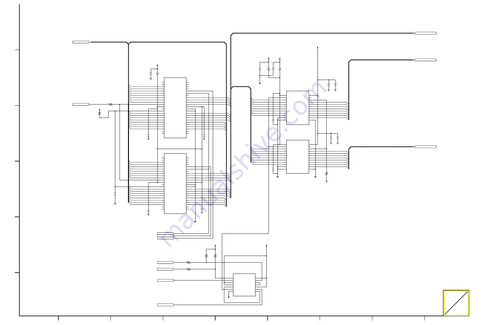
CPUDT[0-7]
CPUDT[0-7]
CE1
CPURD
CPWRH
CPWRH
CPWRL
CDTH[3]
CDTH[2]
CDTH[0]
CPUDT[0]
CPUDT[1]
CPUDT[4]
CDTH[7]
CPUDT[3]
CPUDT[2]
CDTH[2]
CPUDT[7]
CPUDT[6]
CDTH[6]
CDTH[3]
CPUDT[5]
CDTH[5]
CDTH[1]
CDTH[4]
CDATA[8]
CDATA[9]
CDATA[10]
CDATA[11]
CDATA[12]
CDATA[13]
CDATA[14]
CDATA[15]
CDTH[8]
CDTH[9]
CDTH[10]
CDTH[11]
CDTH[12]
CDTH[13]
CDTH[14]
CDTH[15]
CDATA[8-15]
CPA[14]
CPA[3]
CPA[8]
CPA[4]
CPA[5]
CPA[10]
CPA[9]
CPA[6]
CDTH[4]
CPA[2]
CDTH[1]
CPA[17]
CDTH[6]
CDTH[7]
CPA[11]
CPA[1]
CPA[20]
CPA[13]
CDTH[5]
CPA[7]
CPA[19]
CPA[12]
CPA[18]
CPA[15]
CPA[16]
CDTH[0]
CDTH[15]
CDTH[14]
CDTH[13]
CDTH[12]
CDTH[11]
CDTH[10]
CDTH[9]
CDTH[8]
CPA[1]
CPA[2]
CPA[3]
CPA[4]
CPA[5]
CPA[6]
CPA[7]
CPA[8]
CPA[9]
CPA[10]
CPA[11]
CPA[12]
CPA[13]
CPA[14]
CPA[15]
CPA[16]
CPA[17]
CPA[18]
CPA[19]
CPA[20]
VCC 14
1C 13
1Y 12
3C 11
3B 10
3A 9
3Y 8
GND
7
2Y
6
2C
5
2B
4
2A
3
1B
2
1A
1
IC3024
SN74LVC10ANSR
GND 13
GND
12
VCCB(3V) 24
NC 23
A8
10
A7
9
B2 20
B3 19
B4 18
A6
8
B6 16
B7 15
B8 14
GND
11
OE 22
B1 21
B5 17
A5
7
A4
6
A3
5
A2
4
A1
3
DIR
2
VCCA(5V)
1
IC3026
SN74LVCC4245ANS-R
GND 13
GND
12
VCCB(3V) 24
NC 23
A8
10
A7
9
B2 20
B3 19
B4 18
A6
8
B6 16
B7 15
B8 14
GND
11
OE 22
B1 21
B5 17
A5
7
A4
6
A3
5
A2
4
A1
3
DIR
2
VCCA(5V)
1
IC3025
SN74LVCC4245ANS-R
+5V
C3321
0.1
C3322
0.1
GND
GND
GND
GND
GND
GND
009:8C
CPUDT[0-7]
009:8A
CPURD
010:2B;011:8C
FLSHCS
009:8E;011:6C
CS0
GND
N.M.
C3235
C3236
0.1
C3234
0.1
GND
L3061
BLM11A601SPT
N.M.
L3060
L3059
BLM11A601SPT
R3237
22
R3238
22
004:7F;011:2B
CE1
R3235
22
003:3E;004:2F;006:1E;009:8E;011:2A;011:6B
CPA[1-20]
+3V
N.M.
R3240
N.M.
R3239
GND
+3V
GND
010:4F;011:8C
FLSHCS
003:8E;004:5F;006:1E;013:8E;014:5A
CDATA[8-15]
011:8A
CDTH[0-15]
GND
C3232
100P
R3230
1K
GND
R3241
0
003:3E;004:2E;006:1F;009:7A;011:2C;014:2C
CPWRH
GND
GND
+3V
+3V
+5V
NC
48
NC
47
NC
46
NC
45
WE
44
OE
43
RY/BY
42
DQ7
41
DQ6
40
DQ5
39
DQ4
38
VCC
37
VSS
36
VSS
35
DQ3
34
DQ2
33
DQ1
32
DQ0
31
A0
30
A1
29
A2
28
A3
27
NC
26
NC
25
A13
9
NC
24
NC
23
A4
22
A5
21
A6
20
A7
19
A8
18
A9
17
A10
16
A11
15
RESET
14
NC
13
VCC
12
CE
11
A12
10
A14
8
A15
7
A16
6
A17
5
A18
4
A19
3
NC
2
NC
1
IC3023
MBM29F080A-90PFTN
GND
+5V
NC
48
NC
47
NC
46
NC
45
WE
44
OE
43
RY/BY
42
DQ7
41
DQ6
40
DQ5
39
DQ4
38
VCC
37
VSS
36
VSS
35
DQ3
34
DQ2
33
DQ1
32
DQ0
31
A0
30
A1
29
A2
28
A3
27
NC
26
NC
25
A13
9
NC
24
NC
23
A4
22
A5
21
A6
20
A7
19
A8
18
A9
17
A10
16
A11
15
RESET
14
NC
13
VCC
12
CE
11
A12
10
A14
8
A15
7
A16
6
A17
5
A18
4
A19
3
NC
2
NC
1
IC3022
MBM29F080A-90PFTN
009:7A;011:2C
CPWRL
006:1F;009:7A;011:2B;011:6B;014:2C
CPURD
GND
C3237
100P
C3240
100P
C3239
100P
C3238
100P
C3244
0.1
C3243
0.1
C3242
0.1
C3241
0.1
8
F
E
D
C
B
A
7
6
5
4
3
2
1
(I/F Board)
KV-SS905C
Summary of Contents for KV-SS905C
Page 1: ...ORDER NO KM70108670C0 G14 High Speed Color Scanner KV SS905C 1 1 ...
Page 6: ...4 INSTALLATION 4 1 Minimum Space Requirements 6 ...
Page 8: ...8 ...
Page 15: ...2 Tighten all the screws 15 ...
Page 42: ...42 ...
Page 46: ...46 ...
Page 51: ...51 ...
Page 52: ...52 ...
Page 55: ...3 Use your fingers to pull the Retard Roller Door toward you 55 ...
Page 58: ...7 Close the Retard Roller Door 58 ...
Page 59: ...8 Close the Front Door Note Push down the Front Door slowly until it clicks into place 59 ...
Page 61: ...3 Using your fingers open the Retard Roller Cover 61 ...
Page 62: ...4 Pull and remove the Retard Pad in the direction of the arrow 62 ...
Page 64: ...7 Close the Retard Roller Cover 64 ...
Page 66: ...8 DISASSEMBLY INSTRUCTIONS 8 1 Disassembly Flowchart 66 ...
Page 69: ...69 ...
Page 77: ...8 2 9 Back Door Cover 1 Remove the 2 screws 77 ...
Page 78: ...2 Spread the 2 claws of right and left both sides toward the outside 78 ...
Page 84: ...6 Remove the 4 screws B and remove the Board Box Power Box 84 ...
Page 85: ...85 ...
Page 87: ...4 Remove the 2 screws B from the Hopper Motor with plate to remove the Hopper Motor 87 ...
Page 94: ...3 Pull the Lamp Modules out of the Scanner 94 ...
Page 96: ...5 Remove screws 96 ...
Page 97: ...6 Remove the Lamp Holder covers on the Lamp Modules 97 ...
Page 98: ...7 Remove the Lamps from the Lamp Modules in the direction of the arrow 98 ...
Page 106: ...5 Lift the Conveyor Bottom 4 and pull out toward the front of the unit to remove 106 ...
Page 107: ...6 Unhook the Drive Rollers from the notching hole of chassis and remove it 107 ...
Page 109: ...4 Unhook the Conveyor Rollers from the notching hole of chassis and remove it 109 ...
Page 115: ...8 4 3 I F Board 1 Remove 4 screws 2 Pull out the I F Board in the direction of the arrow 115 ...
Page 120: ...4 Remove the 2 screws B and Conveyor Upper 5 120 ...
Page 122: ...8 Remove the screw E and remove the Exit Rear Sensor 122 ...
Page 137: ...4 Remove the 2 screws from FAN 1 137 ...
Page 139: ...5 Remove the 2 screws B from FAN 2 139 ...
Page 169: ...13 2 I F Board SCSI Board 169 ...
Page 170: ...13 3 MOTHER Board 13 4 DRIVE Board 170 ...
Page 237: ...16 1 2 I F Board SCSI Board 237 ...
Page 238: ...16 1 3 MOTHER Board 16 1 4 DRIVE Board 16 1 5 PANEL SENSOR Boards 238 ...
Page 370: ......
Page 371: ......
Page 372: ......
Page 373: ......
Page 374: ......
Page 375: ......
Page 376: ......
Page 377: ......
Page 378: ......
Page 379: ......
Page 380: ......
Page 381: ......
Page 382: ......
Page 383: ......
Page 384: ......
Page 385: ......
Page 386: ......
Page 387: ......
Page 388: ......
Page 389: ......
Page 390: ......
Page 391: ......
Page 392: ......
Page 393: ......
Page 394: ......
Page 395: ......
Page 396: ......
Page 397: ......
Page 398: ......
Page 399: ......
Page 400: ......
Page 401: ......
Page 402: ......
Page 403: ......
Page 404: ......
Page 405: ......
Page 406: ......
Page 407: ......
Page 408: ......
Page 409: ......
Page 410: ......
Page 411: ......
Page 412: ......
Page 413: ......
Page 414: ......
Page 415: ......
Page 416: ......


