(1) Remove th e clam p assembly as described in
section 12.5.
(2) Remove the lifte r shaft clamping retaining ring
draw o u t th e lifte r shaft.
(3) Remove the media lifte r.
(4) Reverse the above procedure to reinstall.
12.13 Media Lifter Removal and Installation
(1) Remove th e PCB as described in section 12.1.
(2) Remove th e c a rtrid g e g u id e assem bly as
described in section 12.7.
(3) Draw out the pins o f the media sensor assembly
fro m th e f o llo w in g lo c a tio n s on th e J3
co n n e c to r: N o 8 ,10, 12.
A t th a t tim e, draw o ut the pins w ith liftin g the
stopper on the connector.
(4) Remove the media sensor assembly m ounting
screw and take out the media sensor assembly.
(5) Reverse the above procedure to reinstall.
12.14 M e d ia Sensor A s s em b ly R e m o v al and
Installation
-2 2 -
Summary of Contents for JU-475-4
Page 1: ...ORDER NO MSD891122000 Service Manual Flexible Disk Storage Drive JU 475 4 Panasonic ...
Page 6: ...6 2 Troubleshooting Flowchart Table6 1 Troubleshooting Flowchart 4 ...
Page 14: ...10 TEST POINTS Printed Circuit Board Top View GND Vout Vout GND TRK0 TP 8 kJ 1 2 ...
Page 30: ...17 CIRCUIT BOARD JU 475 4AGG Component Side Top 28 TP5 L 6 ...
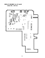
Page 31: ...CIRCUIT BOARD JU 475 4AGG Solder Side Bottom 29 ...
Page 34: ...Matsushita Communication industrial Co Ltd Memory Systems Division ...


