


3
MODULE SPECIFICATIONS
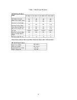
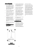
Module specifications are shown in
Table 1 and Figure 1. (Electrical
specifications, mechanical specifica-
tions, module dimensions)
1)
Rated electrical characteristics are
within the range of –5% to +10% of
the values measured at Standard
Test Conditions (STC). STC condi-
tions are; Irradiance of 1000W/m
2
,
25°C cell temperature, AM1.5 and
solar spectral irradiance per IEC
60904-3. Note: At the time of ship-
ment, Panasonic guarantees the
output level of its modules to be -0/
+10% against Rated Power in SPECI-
FICATIONS based on factory inspec-
tion at STC conditions.
2)
Under real conditions, a photovolta-
ic module may experience condi-
tions that produce more current
and/or voltage than reported at
Standard Test Conditions. There-
fore, the Isc value of modules
should be multiplied by a factor of
1.25 to determine ampacity. An
additional factor of 1.25 may be
required for sizing conductors, fus-
es, disconnects, etc. Please refer to
section 690.8 of the National Electric
Code (NEC) for guidelines. The Voc
must be factored according to the
lowest recorded ambient tempera-
ture recorded for the location
where the modules will be installed.
Please refer to section 690.7 of the
NEC for more information regarding
voltage temperature factors.
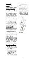
MECHANICAL LOADING
The modules should be mounted at
the four (4) quarter points by the
means shown in Figure 1.
This method offers a maximum load
shown as “Mount Location and
Load Resistance” in Figure 1 in a
static state on the module surface.
Note: This mechanical loading value
was tested using the mounting de-
vice specified in section “MODULE
INSTALLATION”
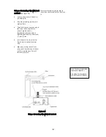
As UL Certified Load Ratings, this
module meets design loads as be-
low.
1)
Positive load with Long frame
mounting
・
33 psf (0-450mm range from edge
・
75 psf (230-380mm range from edge)
2) Negative load with Long frame
mounting
・
33 psf (0-450mm range from edge
・
61 psf(230-380mm range from edge)
・
75 psf (230-345mm range from edge)
3) Positive load with Short frame
mounting
・
33 psf (0-250mm range from edge)
4) Negative load with Short frame
mounting
・
33 psf (0-250mm range from edge)
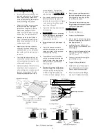
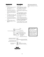
Front
Figure 1. Module Dimension
Backside
Side
Dimension in mm
Mount Locations and Load Resistance
L1
0
230
230
-
L2
450
380
345
-
S1
-
-
-
0
S2
-
-
-
250
50 psf
(2400 Pa)
112 psf
(5400 Pa)
112 psf
(5400 Pa)
50 psf
(2400 Pa)
50 psf
(2400 Pa)
91 psf
(4400 Pa)
112 psf
(5400 Pa)
50 psf
(2400 Pa)
Load Resistance (Positive Load)
Load Resistance (Negative Load)
Mounting location range
Note) Load Resistance shown above is UL Test-Load.
Design load is a value obtained by multiplying the above value by
two thirds.
Note) A module is installed using 4 points, symmetrical mounting within setting range (shaded).
Setting range parameters are shown in “Mount Locations and Load Resistance” table.


