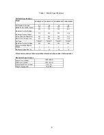
background image

SAFETY PRECAUTIONS 

 

All instructions should be read and 

understood before attempting to 

install, wire, operate, and maintain 

the module. 

 

The installation of modules requires 

a great degree of skill and should  

only be performed by qualified li-

censed professionals, including, 

without limitation, licensed contrac-

tors and licensed electricians. 


 

The installer assumes the risk of all 

injury that might occur during instal-

lation, including, without limitation, 

the risk of electric shock.


 

Before installing modules, contact 

the appropriate authorities to deter-

mine permissions, installation and 

inspection requirements, which 

should be followed.


 

Be sure that the construction or 

structure (roof, etc.) where the 

modules are being installed has 

enough strength.


 

Both roof construction and module 

installation design have an effect on 

the fire resistance of a building. 

Improper installation may contrib-

ute to fire hazards.  Additional de-

vices such as ground fault, fuses, 

and disconnects may be required.


 

For a non-integral module or panel, 

the assembly is to be mounted over 

a fire resistant roof covering rated 

for the application.


 

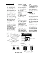
For modules mounted on roofs, 

special construction or structures 

may be required to help provide 

proper installation support.


 

Do not install the module where 

flammable gases or vapors are pre-

sent.


 

Do not use modules of different 

specifications in the same system. 


 


Follow all safety precautions of 

other system components used.


 


In some areas, local electrical codes 

may govern the installation and use 

of modules.


WARNING


To avoid the hazard of electric shock, 

sparks, fire and injury 


 

The modules generate DC electrical 

energy when exposed to sunlight or 

other light sources, so cover the 

entire front surface of the modules 

with a dense, opaque material such 

as a cardboard box, during installa-

tion and handling of the modules.


 

The shock hazard increases as mod-

ules are connected in parallel, pro-

ducing higher current, and as mod-

ules are connected in series, produc-

ing higher voltages.


 

The shock hazard increases as mod-

ules with nominal open-circuit volt-

age (Voc) in excess of 50 V, and/or 

modules rated for maximum system 

voltage in excess of 50 V.


 

Wear suitable clothing, gloves and 

guards to prevent from direct con-

tact with 30 VDC or greater.


 

Work only in dry conditions, with 

dry modules and dry tools.


 

Children and unauthorized persons 

should not be allowed near the 

installation of modules.


 

Do not puncture or damage the 

back sheet of a module.


 

Do not disassemble the module, or 

remove any parts installed by the 

manufacturer.


 

Do not open a junction box's lid. 


 

Do not touch the junction box termi-

nals.


 

Do not change the wiring of bypass 

diodes.


 

Do not connect or disconnect termi-

nals while modules generate elec-

tricity and connect electrical load.


 

Never leave a module unsupported 

or unsecured. 


CAUTIONS


To avoid the hazard of injury, burn and 

damage to the module


 

Use a module for its intended pur-

pose only.


 

Be sure that all other system compo-

nents are compatible, and they do 

not subject the module to mechani-

cal or electrical hazards.


 

Do not artificially concentrate sun-

light on a module.


 

Do not stand or step on a module.


 

When carrying a module, two or 

more people should carry it by its 

frame and wear non-slip gloves.


 

Do not carry a module by its wires or 

junction box.


 

Do not drop a module. 


 

Do not drop anything on the surface 

of a module.


 

Do not hit the back sheet of a mod-

ule by the connector or other 

things.


 

Do not disassemble a module, at-

tempt any repair, open the junction 

box cover, nor remove any parts 

installed by Panasonic. There are no 

user serviceable parts within the 

module or junction box.


 

Do not treat the back sheet or front 

surface with paint or adhesives.


 

Do not use or install broken mod-

ules.


 

Do not touch a module unnecessari-

ly. The glass surface and frames get 

hot.


Summary of Contents for HIT VBHN320KA03

Page 1: ...service names listed in this manual are trademarks or registered trademarks of respective companies General Installation Manual VBHNxxxSA series VBHNxxxKA series Photovoltaic Module HIT Thank you for choosing Panasonic photovoltaic module HIT Please read this manual completely before you install or use of HIT With proper operation and maintenance HIT will pro vide you with clean renewable solar el...

Page 2: ...alla tion and handling of the modules The shock hazard increases as mod ules are connected in parallel pro ducing higher current and as mod ules are connected in series produc ing higher voltages The shock hazard increases as mod ules with nominal open circuit volt age Voc in excess of 50 V and or modules rated for maximum system voltage in excess of 50 V Wear suitable clothing gloves and guards t...

Page 3: ...AL LOADING The modules should be mounted at the four 4 quarter points by the means shown in Figure 1 This method offers a maximum load shown as Mount Location and Load Resistance in Figure 1 in a static state on the module surface Note This mechanical loading value was tested using the mounting de vice specified in section MODULE INSTALLATION As UL Certified Load Ratings this module meets design l...

Page 4: ... 69 6 70 9 70 5 Short Circuit Current Isc 6 07 6 03 5 94 5 89 Cell Type Silicon hetero junction Silicon hetero junction Silicon hetero junction Silicon hetero junction Maximum System Voltage 600 600 600 600 Factory Installed Bypass Diodes 4 4 4 4 Maximum series fuse A 15 15 15 15 Silicon hetero junction Monocrysttaline silicon amorphous silicon hetero junction Mechanical Specifications Length mm i...

Page 5: ...locking sleeve needs to be used with all connectors that are exposed The locking sleeve PV SSH4 is made by STAUBLI and can only be released with a special tool also made by STAUBLI PV MS Locking sleeves are not supplied with mod ules and must be purchased sepa rately BYPASS DIODE When the modules in series strings are shaded partially it may cause reverse voltage across cells or mod ules because t...

Page 6: ... with salt water 3 Heavy snow falls areas 4 Sand and dust damage is excessive at the installation place Heavy dirt areas by sand or dust e g desert a quarry etc 5 Installation in places where there is a concern about deterioration of panel such as heavy air pollution chemically active vapors acid rain and or soot ammonia gas etc UNPACKING AND HANDLING Do not hit the back sheet of a mod ule by the ...

Page 7: ... structure rail Recommendation of bolt torque 10 ft lbs Figure 5 shows that a module should be attached on a mount or support structure rail by corrosive resistant metal clamps Appropriate material should be used for mounting hardware the module frame mounting structure and hardware to prevent itself from corrosion Panasonic does not provide a war ranty for clamps The module war ranty Panasonic pr...

Page 8: ... for off grid or battery charging systems because of their operating voltage Therefore it is not recommended to use them for off grid or charging batteries without using MPPT Maximum Power Point Tracking controller These modules contain factory in stalled bypass diodes If these mod ules are incorrectly connected to each other the bypass diodes ca ble or junction box may be dam aged Do not connect ...

Page 9: ... sistance of the grounding connec tion on the module or can even cause the grounding connection to fail entirely Corrosion can be caused by the effects of weather humidity dirt and so on It can also be caused when two dissimilar met als are in contact galvanic reac tion The module frame material is alumi num magnesium alloy All fasteners nuts bolts washers screws etc must be stainless steel unless...

Page 10: ... washer is placed between the wire and the module frame Choose an adequate size for the cup washer and the flat washer so that the wire is fully clamped between them Note Cup washers are also called ter minal cup washers The cup washers should be stainless steel or a cup washer made of brass may be used only if a large flat washer made of stainless steel is inserted between the module frame and th...

Page 11: ...d lock nut Tighten stainless steel set screw at the torque specified by lug manu facturer to secure copper wire The specified torque is following Ilsco Corp GBL 4DBT 10 14AWG Solid 20 in lbs 4 6AWG Strand 35 in lbs 8AWG Strand 25 in lbs 10 14AWG Strand 20 in lbs Burndy L L C CL501TN 14AWG Solid 35 in lbs 14AWG Strand 35 in lbs 4AWG Strand 45 in lbs Recommended torque value in tightening bolt and n...

Page 12: ...ening bolt and nut is between 1 7 and 2 2 Nm Insert the wire into the wire slot Press down on both ends of the wire Manually or using channel lock pliers push the slider over the base until it covers the base This will terminate the wire For more information please refer to Instruction sheet issued by Tyco Electron ics Note Use the ground holes illustrated in Figure 6 1 Grounding Clip Assemblies T...

Page 13: ...micro fiber cloth and ethanol Never use abrasive detergent strong alkaline detergent strong acid detergent or a detergent which forms a protective layer on the sur face of the glass to clean any part of the module The performance of a solar modules may be reduced Please be very careful since the war ranty will not cover the damages caused by detergents DISCLAIMER OF LIABILITY Panasonic does not as...

Page 14: ...14 Edition Revision Date Revised Item Revised Content NEW Edition 2017 7 12 2nd Edition 2018 5 14 Change of format Representation of layout description sentences REVISION HISTORY ...

Reviews: