background image

Aluminum Electrolytic Capacitor

Design, Specifications are subject to change without notice.  Ask factory for technical specifications before purchase and/ or use.
Whenever a doubt about safety arises from this product, please inform us immediately for technical consulation without fail.


EE18


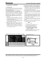
1.3 Common Application Conditions to Avoid

The following misapplication load conditions will
c a u s e   ra p i d   d e t e r i o r a t i o n   t o   c a p a c i t o r   e l e c t r i c a l
p a r a m e t e r s.  l n   a d d i t i o n ,   ra p i d   h e a t i n g   a n d   g a s
generation within the capacitor can occur causing
the pressure relief vent to operate and resuItant
leakage of electrolyte.  Under extreme conditions,
explosion and fire could result. Leakinq electrolyte
is combustible and electrically conductive.

(1) Reverse Voltaqe


DC capacitors have polarity. Verify correct polarity

      before  inser tion.    For  circuits  with  changing  or
      uncer tain polarity,use DC bipolar capacitors. DC
      bipolar capacitors are not suitable for use in AC
       circuits.

(2) Charqe/Discharqe Applications


   Standard capacitors are not suitable for use in

       repeating  charge/discharge  applications.  Fo r
       charqe/discharqe applications consult  us and advise
       actual conditions.

(3) Overvoltage


    Do not  appIy voltaqes exceeding the maximum

      specified rated voltages. Voltage up to the surge
       voltage rating are acceptable for shor t periods of
       time.  Ensure that the sum of the DC voltage and
         the  super imposed  AC  r ipple  vo l t a g e   does not
      exceed the rated voltage.

(4) Ripple Current


    Do not apply ripple currents exceeding the maximum

      specified value. For high ripple current applications,
      use  a  capacitor  designed  for  high  rippIe  currents
      or contact us with your requirements.
      Ensure that allowable ripple currents superimposed
       on low DC bias voltages do not cause reverse voltage
      conditions.

1.4 Using Two or More Capacitors in Series
      or Parallel

(1) Capacitors Connected in Parallel


    The circuit resistance can closely approximate the

      ser ies resistance of the capacitor causing an
              i m b a l a n c e   o f   r i p p l e   c u r r e n t   l o a d s   w i t h i n   t h e
      capacitors.  Careful  design  of  wiring  methods  can
      minimize the possibility of excessive ripple currents
      applied to a capacitor.

(2) Capacitors Connected in Series


    Nor mal  DC  leakage  curren t  differences  among

       capacitors can cause voltage imbalances. The use
       of voltage divider shunt resistors with consideration
       to leakage currents, can prevent capacitor voltage
       imbaIances.

1.5 Capacitor Mounting Considerations

(1) DoubIe - Sided Circuit Boards


     Avoid wir ing Patter n r uns which pass between

       the mounted capacitor and the circuit board. When
       dipping into a solder bath, excess solder may collect
           u n d e r   t h e   c a p a c i t o r   b y   c a p i l l a r y   a c t i o n   a n d


   shortcircuit the anode and cathode terminals.

(2) Circuit Board Hole Positioning


The vinyl sleeve of the capacitor can be damaged

       i f   s o l d e r   p a s s e s   t h r o u g h   a   l e a d   h o l e   f o r
       subsequently processed parts. Special care when
       locating hole positions in proximity to capacitors is
       recommended.

(3) Circuit Board Hole Spacing


The circuit board holes spacing should match the

      capacitor lead wire spacing within the specified
       tolerances. Incorrect spacing can cause excessive
       lead wire stress during the insertion process. This
       may resuIt in premature capacitor failure due to
      short or open circuit, increased leakage current,
      or electrolyte leakage.

(4)Land/Pad Pattern


 The circuit board land/pad pattern size for chip

       capacitors is specified in the following table.

        [ Table of Board Land Size vs. Capacitor Size ]

 Among others, when the size a is wide , back fillet can
 not  be made,  decreasing fitting strength.

 ❉ 

Decide considering mounting condition, solderability

    and  fitting strength, etc. based on the design
    standards of your company.

b     a      b

c

Board land part

Size
A(

φ

3)

B(

φ

4)

C(

φ

5)

D(

φ

6.3)

E(

φ

8 x 6.2L)

F(

φ

8 x 10.2L)

G(

φ

10 x 10.2L)

  a
0.6
1.0
1.5
1.8
2.2
3.1

4.6

  b
2.2
2.5.
2.8
3.2
4.0
4.0
4.1

  c

1.5
1.6
1.6
1.6
1.6
2.0
2.0

(mm)

Summary of Contents for HFQ EE26

Page 1: ...18 post test requirements at 20 C 6 3mmdia L L 16 L 1 0 max φd 0 05 14min min φD 0 5 max φ10 P 0 5 φD 0 5 max φ8 P 0 5 L 20 L 2 0 max Body Dia φD Body LengthL Lead Dia φd Lead space P 15 to25 30 to 40 0 45 0 5 0 5 0 6 0 6 0 6 0 8 0 8 0 8 1 5 2 2 5 3 5 5 5 5 7 5 7 5 4 5 6 3 8 10 12 5 16 18 Frequency correction factor for ripple current W V V DC 60 120 1k 10k 100k Frequency Hz 0 55 0 65 0 85 0 90 1 ...

Page 2: ...0 0 920 0 600 0 400 0 340 0 240 0 180 0 240 0 180 0 130 0 110 0 090 0 130 0 084 0 068 0 060 0 048 0 042 0 092 0 068 0 056 0 050 0 044 0 036 0 076 0 056 0 050 0 046 0 042 0 034 1 000 0 650 0 460 0 300 0 200 0 170 0 120 0 090 0 120 0 090 0 065 0 055 0 045 0 065 0 042 0 034 0 030 0 024 0 021 0 046 0 034 0 028 0 025 0 022 0 018 0 038 0 028 0 025 0 023 0 021 0 017 120 175 235 290 400 445 575 760 625 79...

Page 3: ...60 0 320 0 220 0 180 0 150 0 260 0 160 0 140 0 120 0 100 0 086 0 168 0 106 0 088 0 066 0 056 0 052 0 140 0 100 0 082 0 062 0 054 0 050 2 500 1 300 0 900 0 600 0 400 0 300 0 230 0 160 0 230 0 160 0 110 0 090 0 075 0 130 0 080 0 070 0 060 0 050 0 043 0 084 0 053 0 044 0 033 0 028 0 026 0 070 0 050 0 041 0 031 0 027 0 025 90 155 215 260 360 410 500 670 510 640 890 1040 1300 920 1200 1440 1680 1850 20...

Page 4: ...and Life Expectancy 1 Expected life is affected by operating temperature Generally each 10 C reduction in temperature will double the expected life Use capacitors at the lowest p o s s i bl e t e mperature below the maximum guaranteed temperature 2 If operating conditions exceed the maximum guaranteed limit rapid eIectrical parameter deterioration will occur and irreversible damage will result Che...

Page 5: ...age applied Excessive ripple current Reverse voltage applied Severe charging discharging AC voltage applied Used for a high temperature Used for a long period of time Stress applied to leads Use of Halogenated solvent Use of adhesive Use of coating material Defect of oxide film Insufficient electrolyte Metal particles in capacitor Burr s on foil leads Leads improperly connected Mechanical stress L...

Page 6: ...l 1 Capacitors Connected in Parallel The circuit resistance can closely approximate the series resistance of the capacitor causing an imbalance of ripple current loads with in the capacitors Careful design of wiring methods can minimize the possibility of excessive ripple currents applied to a capacitor 2 Capacitors Connected in Series Normal DC leakage current differences among capacitors can cau...

Page 7: ...ene or xylene and then exposed to high temperatures Always consider safety when designing equipment and circuits Plan for worst case failure modes such as short circuits and open circuits which could occur during use 1 Provide protection circuits and protection devices to allow safe failure modes 2 Design redundant or secondary circuits where possible to assure continued operation in case of main ...

Page 8: ...Cleaner P3 375 Telpen Cleaner EC 7R Clean thru 750H Clean thru 750L Clean thru 710M Techno Cleaner 219 Techno Care FRW 17 Techno Care FRW 1 Techno Care FRV 1 IPA isopropyl alcohol The use of ozone depleting cleaning agents are not recommended in the interest of protecting the environment 2 Avoid using the following solvent groups unless specifically allowed for in the specification Halogenated cle...

Page 9: ...the pressure relief vent of the capacitor operates immediately turn off the equipment and disconnect from the power source This will minimize additional damage caused by the vaporizing electrolyte 2 Avoid contact with the escaping electrolyte gas which can exceed 100 C temperatures If electrolyte or gas enters the eye immediately flush the eye with large amounts of water If electrolyte or gas is i...

Page 10: ...l to prevent explosion due to internal pressure rise Capacitors should be incinerated at high temperatures to prevent the release of toxic gases such as chlorine from the polyvinyl chloride sleeve etc Dispose of as solid waste L o c a l l a w s m a y h a v e s p e c i f i c d i s p o s a l requirements which must be followed The application guidelines above are taken from Technical Report EIAJ RCR...

Reviews: