17
Recording 3D video
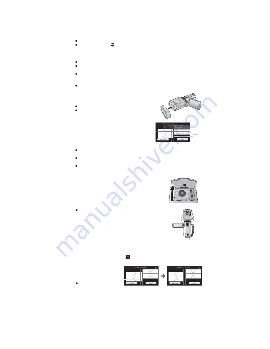
When using for the first time, be sure to adjust the 3D Conversion Lens attachment position.
Turn off the unit.
Change the mode to
.
1
Attach the 3D Conversion Lens to the unit.
2
Turn on the unit.
Turn on with the unit in a horizontal state.
The 3D Conversion Lens adjustment mode screen will appear automatically after
performing the initial setting.
If the 3D Conversion Lens adjustment mode screen does not appear automatically,
set from the menu.
([SETUP]
[3D CONV. LENS SETUP])
If the unit is turned on with the USB cable still connected, the USB connection will take
priority.
3
Attach the lens front cap to the 3D
Conversion Lens.
2 screens will appear.
The horizontal line for adjustment on the lens front cap is
displayed on the screen.
Guide Line
4
Touch [ADJUST].
If the black vertical line and the black horizontal line are within the red guidelines
and
adjustment is not required, touch [EXIT] and proceed to Step 11.
Perform the adjustment in a bright location where the horizontal line for adjustment will be
clearly visible.
The 3D Conversion Lens cannot be adjusted using the viewfinder.
5
Open the adjustment dial cover.
When turning the adjustment dials, hold the 3D Conversion
Lens in the palm of your hand from the bottom and operate
with the fingers of your other hand without applying too much
force from above. When checking the adjustment, check with
your fingers off the adjustment dials.
6
(After checking the operation description, touch [NEXT].)
To adjust the horizontal position, rotate the horizontal image
position adjustment dial
so that the black vertical line is between
the red guidelines
.
Touch [NEXT].
Summary of Contents for HDC-SDT750EB
Page 10: ...10 3 5 Formatting ...
Page 11: ...11 4 Specifications ...
Page 12: ...12 ...
Page 13: ...13 ...
Page 22: ...22 7 Troubleshooting Guide ...
Page 28: ...28 Fig D2 9 3 2 Removal of the ESD P C B Unit Fig D3 ...
Page 29: ...29 9 3 3 Removal of the Cover Board Unit Fig D4 9 3 4 Removal of the Top Case Unit Fig D5 ...
Page 30: ...30 Fig D6 9 3 5 Removal of the Front Unit Fig D7 ...
Page 34: ...34 9 3 13 Removal of the LCD Case Unit Fig D18 9 3 14 Removal of the LCD Hinge Unit Fig D19 ...
Page 35: ...35 9 3 15 Removal of the Monitor P C B Unit Fig D20 Fig D21 ...
Page 37: ...37 Fig D25 9 3 18 Removal of the Front Case Unit Fig D26 Fig D27 ...
Page 39: ...39 Fig D30 9 3 20 Removal of the EVF Unit Fig D31 9 3 21 Removal of the Top Frame Fig D32 ...
Page 45: ...45 Fig D49 9 3 36 Removal of the Focus Guide Pole L and Focus Guide Pole S Fig D50 ...
Page 48: ...48 Fig L4 9 5 4 Removal of the Fixing Base and Fixing Dial Fig L5 ...
Page 49: ...49 9 5 5 Removal of the Horizontal Position Adjustment Dial Unit Fig L6 ...
Page 75: ...S 22 ...
Page 89: ...S 36 S7 3 EVF Section B23 59 B22 58 60 61 62 63 65 64 66 67 68 69 70 72 71 73 74 75 76 77 B24 ...
Page 90: ...S 37 S7 4 LCD Section 27 28 29 26 30 32 23 31 25 22 B7 B8 24 ...


