background image

47

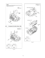
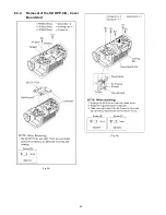
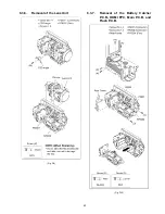
8.3.10. Removal of the Front P.C.B.

(Fig. D18)

8.3.11. Removal of the Barrier Motor Unit

(Fig. D19)

(Fig. D20)

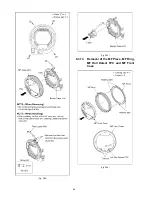
8.3.12. Removal of the Flash, Barrier Case

Unit

(Fig. D21)

Summary of Contents for HC-X910GC

Page 1: ...n is a violation of law ORDER NO VM1301005CE B27 High Definition Video Camera Model No HC X920P HC X920PC HC X920EB HC X920EE HC X920EF HC X920EG HC X920EP HC X929EG HC X920MGC HC X920MGK HC X920MGN HC X910PU HC X910GC Colour K Black Type S Silver Type only HC X929EG ...

Page 2: ... Search History Indication 27 6 3 Power ON Self Check Result Display 28 6 4 Forced full flash emission 28 6 5 Erasing the lock histories 29 6 6 Camera data indications while the video playback 29 6 7 Adjustment function for the Service 30 6 8 Restore the backed up adjustment data 31 6 9 Touch Panel Calibration 32 7 Service Fixture Tools 33 7 1 When Replacing the Main P C B 33 7 2 Service Position ...

Page 3: ...exposed to shock hazards 1 2 Leakage Current Cold Check 1 Unplug the AC cord and connect a jumper between the two prongs on the plug 2 Measure the resistance value with an ohmmeter between the jumpered AC plug and each exposed metal lic cabinet part on the equipment such as screwheads connectors control shafts etc When the exposed metal lic part has a return path to the chassis the reading should ...

Page 4: ...e capacitor also can be discharged according to the following procedures Discharging Procedure 1 Refer to the disassemble procedure and Remove the necessary parts unit 2 Put the insulation tube onto the lead part of Resistor ERG5SJ102 1kΩ 5W an equivalent type of resistor may be used 3 Put the resistor between both terminals of capacitor on FLASH P C B for approx 5 seconds 4 After discharging conf...

Page 5: ...ly a grounded tip soldering iron to solder or unsolder ES devices 4 Use only an antistatic solder removal device Some solder removal devices not classified as antistatic ESD protected can generate electrical charge sufficient to damage ES devices 5 Do not use freon propelled chemicals These can generate electrical charges sufficient to damage ES devices 6 Do not remove a replacement ES device from...

Page 6: ...must not be used until a replacement cover is obtained A replacement fuse cover can be purchased from your local Panasonic Dealer If the fitted moulded plug is unsuitable for the socket outlet in your home then the fuse should be removed and the plug cut off and disposed of safety There is a danger of severe electrical shock if the cut off plug is inserted into any 13 ampere socket If a new plug i...

Page 7: ...essive heat or discharge It must therefore only be fitted in requirement designed specifically for its use Replacement batteries must be of same type and manufacture They must be fitted in the same manner and location as the original battery with the correct polarity contacts observed Do not attempt to re charge the old battery or re use it for any other purpose It should be disposed of in waste p...

Page 8: ...should be well molten and mixed with the original lead free solder Remove the remaining lead free solder on the P C B cleanly for soldering of the new IC Since the melting point of the lead free solder is higher than that of the normal lead solder it takes the longer time to melt the lead free solder Use the soldering iron more than 70W equipped with the temperature control after setting the tempe...

Page 9: ...P X929EG e HC X920EE f HC X920MGN g HC X920MGK h HC X920MGC X910PU GC What is the difference is that the INITIAL SETTING data which is stored in Flash ROM mounted on Main P C B 3 4 1 Defining methods To define the model suffix to be serviced refer to the rating label and caution label which are putted on the Unit NOTE After replacing the MAIN P C B be sure to achieve adjustment ...

Page 10: ...10 3 5 Formatting ...

Page 11: ...e P C B might sometimes occur by rapid heating In order to improve the success rate of IC replacement for repair it would be required to work out baking of replacement IC and defective P C B before replacing IC Please refer the way of baking as follows Replacement IC and defective P C B must be put in the heater together Baking temperature and time Hour 80 C 24 hour ...

Page 12: ...12 4 Specifications 4 1 For NTSC Areas ...

Page 13: ...13 ...

Page 14: ...14 ...

Page 15: ...15 ...

Page 16: ...16 ...

Page 17: ...17 4 2 For PAL Areas ...

Page 18: ...18 ...

Page 19: ...19 ...

Page 20: ...20 ...

Page 21: ...21 ...

Page 22: ...3D Conversion Lens attachment part concave 14 Lens LEICA DICOMAR 15 AF assist lamp 16 Recording lamp A V 8 10 9 11 14 12 15 16 13 6 7 4 5 3 2 1 17 SD card cover 18 Tripod receptacle If you attach a tripod which has 5 5 mm 0 22 S screw or larger it may damage this unit 19 Access lamp ACCESS 20 Card slot 21 Photoshot button 22 Zoom lever W T In Motion Picture Recording Mode or Still Picture Recordin...

Page 23: ...e heard depending on the microphone type In this case please switch to the battery for the power supply and the noise will stop 33 Headphone terminal Excessive sound pressure from earphones and headphones can cause hearing loss Listening at full volume for long periods may damage the user s ears 34 DC input terminal DC IN Do not use any other AC adaptors except the supplied one 35 Mode switch 36 V...

Page 24: ... finger Touch Touch and release the touch screen to select icon or picture Touch the center of the icon Touching the touch screen will not operate while you are touching another part of the touch screen Slide while touching Move your finger while pressing on the touch screen About the operation icons Touch when changing a page or performing settings Touch to return to the previous screen How to us...

Page 25: ...vie of the Creative Control Mode Displayed only in Time Lapse Rec of the Creative Control Mode Scene Mode and the Manual Mode Displayed only when connected to a TV To display the Touch Menu Do not touch on the LCD monitor with hard pointed tips such as ball point pens Touch Menu Recording Mode Playback Mode Display of the Touch Menu will disappear when no touch operation is performed for a specifi...

Page 26: ...y indication Display the camera system error cord for three histories saved in EEPROM 5 Power ON self check result display Power ON self check function to diagnose correct function of the device and interface between devices result display 9 Forced full flash emission Forced full flash emission for discharging the capacitor on FLASH P C B and set to prohibit charge 10 Erasing the lock histories Er...

Page 27: ...6 2 Lock Search History Indication Touch the 4 of LCD select Lock search history indication Operation specifications Indication contents Lock search history indication Display the camera system error cord for three histories saved in EEPROM The error cord contents which are displayed Touch the BAK of LCD to end the service mode and then POWER OFF Error code Function 51 Focus control is abnormal 52...

Page 28: ...M UNI Internal communication test of IC3401 Display other than OK are abnomalities of each lines Cutting of battery connection or AC power supply connection to end the service mode 6 4 Forced full flash emission Touch the 9 of LCD select Forced full flash execution Operation specifications Indication contents Discharging the capacitor without using register Forced full flash emission for charge ca...

Page 29: ...ss the power button and turn off 6 6 Camera data indications while the video playback Touch the 12 of LCD select indicating the camera informations while playing back the recorded video Operation specifications Indication contents While playing back the recorded videos the camera informations Shutter speed Iris value White balance and focal length are superimposed on the LCD screen Press the power...

Page 30: ...field service For a detailed content such as the adjustment procedure refer to 9 Measurements and Adjustments Setting of the file name for adjustment data backup to SD card Model setting Execution of adjustment data backup to SD card Checking of Switches Camera adjustment Iris Gyro OIS and Missing pixels Zoom Tracking adjustments Indoor White Balance Adjustment CH GAIN PWM WB Outdoor White Balance...

Page 31: ...t Operation Specifications Function description Restore the adjustment data to new or repaired Main P C B from SD card that the data backed up from original Main P C B before repairs or replacement To backup the adjustment data use 6 7 Adjustment function for the Service Restoring procedure Press the power button and turn the unit off ...

Page 32: ...Panel Calibration Touch the 16 of LCD select the calibration of touch panel Operation Specifications Function description Calibrate the touch positions of the touch panel Press the power button and turn the unit off ...

Page 33: ...ble S1 Extension Cable List No Parts No Connection Form 1 VFK1951 FP6004 MAIN MONITOR FPC 39PIN 0 3 FFC 2 RFKZ0564 FP851 BATTERY CATCHER EVF Unit 23PIN 0 3 FFC 3 RFKZ0444 PP6005 MAIN PS6751 BATTERY CATCHER 50PIN 0 5 B to B 4 VFK1895 PP6006 MAIN PS7001 FLASH 40PIN 0 5 B to B 5 VFK1895 PP6002 MAIN PS3901 SD OP 40PIN 0 5 B to B 6 VFK1582A1225 or VFK1388 FP3902 SD OP MIC AMP UNIT 12PIN 0 5 FFC 7 VFK15...

Page 34: ... B Refer to HOW TO DISCHARGE THE CAPACITOR ON FLASH P C B The capacitor voltage is not lowered soon even if the AC Cord is unplugged or the battery is removed 2 Be careful of the high voltage circuit on FLASH P C B 3 DO NOT allow other parts to touch the high voltage circuit on FLASH P C B ...

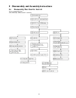
Page 35: ...35 8 Disassembly and Assembly Instructions 8 1 Disassembly Flow Chart for the Unit This is a disassembling chart When assembling perform this chart conversely ...

Page 36: ...36 8 2 PCB Location ...

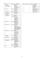
Page 37: ...sh P C B Fig D10 4 Screws N 2 Screws O Rear Frame P6001 Connector P6302 Connector FP6004 Flex Fig D11 Battery Catcher P C B Heat Radiation SheetA 2 Screws P FP6402 Flex HDMI FPC 3 Screws Q 2 Ribs Main Heat Radiation Board Fig D12 PP6006 Connector 1 Projection part Main P C B 2 Screws R 1 Projection part Flash P C B 8 Fan Motor Fig D13 1 Screw S Fan Frame 1 Locking tab 2 Ribs Fan Damper Fan Motor 9...

Page 38: ...s 2 Ribs 1 Locking tab Camera Opreation Angle Camera Opreation Case Camera Opreation Button Camera Damper Sheet CAM Func FPC 20 Microphone Unit Fig D32 2 Ribs Mic Cushion A Mic Cushion B Microphone Unit Mic Cushion C Mic Case 21 Prism Unit Optical Filter Fig D33 2 Screws h Prism Unit Optical Filter 22 Stepping Motor Fig D34 Solder 4 points 2 Screws i Fig D35 Stepping Motor 23 EVF Slide Case EVF EX...

Page 39: ...39 8 3 1 Removal of the Side Case L Unit Fig D1 Fig D2 ...

Page 40: ...40 8 3 2 Removal of the SD OP P C B Cover Board Unit Fig D3 Fig D4 ...

Page 41: ...41 8 3 3 Removal of the ESD P C B HC X920M only Fig D5 8 3 4 Removal of the Top Case Unit Fig D6 ...

Page 42: ...42 Fig D7 8 3 5 Removal of the Front Case Unit Fig D8 ...

Page 43: ...43 8 3 6 Removal of the Lens Unit Fig D9 8 3 7 Removal of the Battery Catcher P C B HDMI FPC Main P C B and Flash P C B Fig D10 ...

Page 44: ...44 Fig D11 Fig D12 ...

Page 45: ...45 8 3 8 Removal of the Fan Motor Fig D13 8 3 9 Removal of the LCD Panel Unit Monitor P C B Fig D14 Fig D15 ...

Page 46: ...46 Fig D16 Fig D17 ...

Page 47: ...47 8 3 10 Removal of the Front P C B Fig D18 8 3 11 Removal of the Barrier Motor Unit Fig D19 Fig D20 8 3 12 Removal of the Flash Barrier Case Unit Fig D21 ...

Page 48: ...48 Fig D22 Fig D23 8 3 13 Removal of the MF Piece MF Ring MF Holl Detect FPC and MF Front Case Fig D24 ...

Page 49: ...3 14 Removal of the EVF Unit Fig D25 8 3 15 Removal of the Top Frame Unit Fig D26 8 3 16 Removal of the Wi Fi P C B HC X920 X920m X929 only Fig D27 8 3 17 Removal of the Operation Unit DC Jack P C B Fig D28 ...

Page 50: ...50 Fig D29 8 3 18 Removal of the Mic Amp P C B Fig D30 8 3 19 Removal of the CAM Func FPC Fig D31 ...

Page 51: ...51 8 3 20 Removal of the Microphone Unit Fig D32 8 3 21 Removal of the Prism Optical Filter Fig D33 8 3 22 Removal of the Stepping Motor Fig D34 ...

Page 52: ...52 Fig D35 8 3 23 Removal of the EVF Slide Case EVF EXT P C B Fig D36 ...

Page 53: ...53 Fig D37 8 3 24 Removal of the LCD Fig D38 8 3 25 Removal of the EVF Lens A B C Fig D39 ...

Page 54: ...era An exclusive jig are necessary for electric adjustment Connection method of the main unit and an exclusive adjustment jig as follows 9 1 1 Adjustment Procedure Connect the main unit to AC adaptor Set the unit to the service mode and execute 14 Adjustment function for the service Figure of connection Figure of image when adjustment ...

Page 55: ... focus chart VFK1164TCM02 VFK1164TCM03 Same as DSC Coupling ring For lens sizes Collimator Joint to lens CC filter 3100K 5100K VFK1164CC10G Need 2 set For indoor outdoor white balance adjutment C2 Filter 5100K VFK1164LBB2 For outdoor white balance adjustment C8 Filter 5100K VFK1164LBB8 For outdoor white balance adjustment ND Filter 0 1 3100K VFK1164ND01 For indoor white balance adjustment ND Filte...

Page 56: ...56 Level Shot Adjutment Chart ...

Page 57: ...57 9 1 2 Adjustment Items Adjustment item as follows ...

Page 58: ...ing is performed using 1 of service mode menu Refer to 6 Service mode and 10 Factory Setting Execute adjustment function for service 1 Set the mode switch Motion Picture Recording mode 2 While the power is turned OFF keep pressing the Power button Zoom lever to W side and intelligent auto Manual button for more than 3 seconds until the top screen of the Service Mode Menu being displayed 3 Touch th...

Page 59: ...or backup to SD card 2 Model setting 3 Backing up adjustment data to SD card 4 Checking switches 5 Camera adjustment Iris Gyro OIS Missing pixels compensation 6 Zoom tracking adjustment 7 Indoor white balance adjustment CH GAIN PWM WB 8 Outdoor white balance adjustment PWM WB 9 Level shot adjustment ...

Page 60: ...60 ...

Page 61: ...61 ...

Page 62: ...62 ...

Page 63: ...63 ...

Page 64: ...64 ...

Page 65: ...65 ...

Page 66: ...66 ...

Page 67: ...ds until the top screen of the Service Mode Menu being displayed 3 Touch the 1 of LCD 4 Touch the YES of LCD 5 After few seconds END is displayed or ESD NODATA as NG is displayed on LCD monitor Cutting of battery connection or AC power supply connection as a completion of the FACTORY SETTINGS After recording at least once even if the physical format of the build in memory will be performed ESD NOD...

Page 68: ...tialize the Wi Fi data settings HC X920 X920M X929 only 7 Confirm that the data area of built in memory is cleared HC X920M only 8 Confirm that the built in memory cappacity is correct HC X920M only Checking of the built in memory mounting error HC X920M If the Factory Settings is completed physical format of the build in memory is not performed execute physical format according to the following p...

Page 69: ...alog Analog Analog IC6301 YAW PITCH GYRO SENSOR IC6302 G SENSOR CLK72 IC3402 DDR SDRAM 2Gbit IC901 SUB LVDS COLOR EVF PANEL IC3401 IC3701 AVIO IC1001 1501 BATTERY CHARGER POWER CIRCUIT IC2304 RTC NOTE VIDEO SIGNAL AUDIO SIGNAL CLK or CONTROL LINE IC301 CAMERA DSP SIRIUS X2301 32 768kHz EXTERNAL MIC Q4901 4904 4907 4908 MIC AMP g o l a n A g o l a n A TOUCH PANEL IC2701 3D ADAPTOR DET IC6351 ROLL G...

Page 70: ...CLKEN AL29 QR3411 QR3413 PW REG 3V GLVDL PORL AD TPY RIGHT AD TPX BOT AD TPY LEFT AD TPX TOP SEL1 ON LOW S S2T Y TPNL S T2S X TPNL S CS SEL2 TP S CK SEL1 TP SEL2 ON LOW SEL1 ON HI SEL2 ON HI AF25 QR3412 QR3410 X RIGHT X LEFT Y TOP Y BOTTOM 1 2 3 4 FP905 IC3404 CONFIRM SYSTEM SCK P10 6 8 SDA 7 RESET GPIOF7 S NOTICE CS S NOTICE RESET GPIOE19 GPIOE21 EVF SLIDE SW E LCD OPEN 2 G11 B14 QR1451 FAN CONTR...

Page 71: ...CD CLKP LCD CLKN LCD AL5 AK5 AL7 AK7 AL6 AK6 LCD LVDS 0P LCD LVDS 0N LCD LVDS 1P LCD LVDS 1N LCD LVDS CLKP LCD LVDS CLKN 85 72 69 62 59 52 24 17 14 7 To IC901 SUB LVDS To LCD PANEL USB DET H 12 PW VBUS PW WIFI3V PW WIFI3 2V EVF MODULE VCLKO LCD YCO LCD0 P30 CLK27 EVF BUS13 EVFYC0 7 BUS24 WIDAT0 3 BUS24 SDDAT0 3 BUS24 ES1DT0 3 S CLK EVF S CS EVF GPIOC1 AF21 GPIOB20 CS EVF AH1 AH6 AE6 GPIOB19 P31 AE...

Page 72: ... WCLK1 CLK LR1 CLK B1 CLK12 M SDOUT 38 AIDAT0 42 WCLK0 CLK LR0 BCLK0 44 CLK B0 RL3707 RL3706 RL3705 RL3704 RL3703 RL3702 RL3701 RL3709 RL3708 G EXTMICL G MIC OUT R G MIC OUT L G MIC OUT B G MIC OUT F LCD PANEL BRGOUT R0 7 BRGOUT B0 7 BRGOUT G0 7 G5 H3 DO23 DO16 DI23 DI16 H9 J6 DO15 DO8 DI15 DI8 E8 G7 E9 D9 D8 D7 DO7 XHD OUT DE OUT XVD OUT CLK OUT C9 B9 A8 CLKIN XHDIN XVDIN DO0 DI7 DI0 IC902 LCD DR...

Page 73: ... XHS SCK SDI XVS BUS288 RD1 P BUS288 RD1 M BUS288 RD2 P BUS288 RD2 M BUS288 RD3 P BUS288 RD3 M BUS288 RD4 P BUS288 RD4 M BUS288 RCK P BUS288 RCK M DOAP R DOAM R DOBP R DOBM R DOCP R DOCM R DODP R DODM R DCKP R DCKM R DOAP DOAM DOBP DOBM DOCP DOCM DODP DODM DCKP DCKM DOAP G DOAM G DOBP G DOBM G DOCP G DOCM G DODP G DODM G DCKP G DCKM G DOAP B DOAM B DOBP B DOBM B DOCP B DOCM B DODP B DODM B DCKP B ...

Page 74: ...01 CAMERA DSP NSCS LEN S NSCS LEN DACLD LEN S DACLD LEN GPIO23 GPIO21 E LENS RST L SDI LEN SDO LEN QR732 LEDCONT LEN B21 B24 D23 S LENDAT L2P SCK LEN S SCK LEN A22 A23 C23 S LENDAT P2L A24 CH718 CH722 CH723 CH721 CH719 CH720 4 5 3 1 IC708 LOGIC IC D Q VCC LE IC707 INVERTER PW REG3V S DAT 2LEN 4 5 3 1 IC6352 GYRO AMP VDD OUT IN IN PW GYRO 3V G GYRO R GYROR OFS S GYRO CSB S GYRO SCK S GYRO SI S GYRO...

Page 75: ...502 COMPARATOR 8 6 7 B OUT B IN 5 B IN V 1 3 2 A IN A IN 4 GND A OUT SDA1 SCL1 S SDA AV CH S CLK AV CH GPIOF6 CHG EN BAT V IP6752 IP6801 QR1503 4 QR1101 CL1105 5 1 VOUT VSS CNT 4 NC IC2303 REGULATOR 4 1 OUT VSS 2 VDD 3 NC IC2302 VOLTAGE DET 3 VIN QR2301 Q2302 2 BKUP 8 IC6001 AND GATE CL1103 PW REG3V T31 T30 C27 GPIOB13 BATT RXD BATT TXD GPIOB14 ADC07 D25 ADC10 MICON T B8 GPIOF23 LCD BL ON PW STNOR...

Page 76: ...0 39 38 37 36 35 34 33 32 31 30 29 28 27 26 EVF SLIDE SW PW EVF2R5V CLK27 EVF BATT BUS13 EVFYC0 BUS13 EVFYC1 BUS13 EVFYC2 BUS13 EVFYC3 BUS13 EVFYC4 BUS13 EVFYC5 BUS13 EVFYC6 BUS13 EVFYC7 S DO EVF S CS EVF S CLK EVF PW EVFBL5V PW REG3V S ACCEL SCL S ACCEL SDA GYRO GND GYRO GND S GYRO CSB S GYRO SCK S GYRO SO S GYRO SI BATT BATT BATT BATT BATT BATT BATT BATT T BATT D PW ADP PW ADP PW ADP PW ADP PW A...

Reviews: