4
1.4.
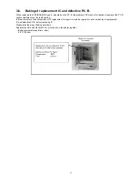
How to Discharge the Capacitor on Flash P.C.B.
CAUTION:
1.
Be sure to discharge the capacitor on FLASH P.C.B..
2.
Be careful of the high voltage circuit on FLASH P.C.B. when servicing.
Before disassembling, perform “6.4. Forced full flash emission” for discharging capacitor.
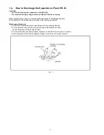
The capacitor also can be discharged according to the following procedures.
[Discharging Procedure]
1. Refer to the disassemble procedure and Remove the necessary parts/unit.
2. Put the insulation tube onto the lead part of Resistor (ERG5SJ102:1k
Ω
/5W).
(an equivalent type of resistor may be used.)
3. Put the resistor between both terminals of capacitor on FLASH P.C.B. for approx. 5 seconds.
4. After discharging confirm that the capacitor voltage is lower than 10V using a voltmeter.
Fig. F1
Summary of Contents for HC-X910GC
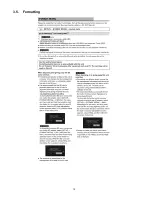
Page 10: ...10 3 5 Formatting ...
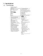
Page 12: ...12 4 Specifications 4 1 For NTSC Areas ...
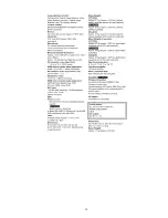
Page 13: ...13 ...
Page 14: ...14 ...
Page 15: ...15 ...
Page 16: ...16 ...
Page 17: ...17 4 2 For PAL Areas ...
Page 18: ...18 ...
Page 19: ...19 ...
Page 20: ...20 ...
Page 21: ...21 ...
Page 36: ...36 8 2 PCB Location ...
Page 39: ...39 8 3 1 Removal of the Side Case L Unit Fig D1 Fig D2 ...
Page 40: ...40 8 3 2 Removal of the SD OP P C B Cover Board Unit Fig D3 Fig D4 ...
Page 42: ...42 Fig D7 8 3 5 Removal of the Front Case Unit Fig D8 ...
Page 44: ...44 Fig D11 Fig D12 ...
Page 46: ...46 Fig D16 Fig D17 ...
Page 52: ...52 Fig D35 8 3 23 Removal of the EVF Slide Case EVF EXT P C B Fig D36 ...
Page 53: ...53 Fig D37 8 3 24 Removal of the LCD Fig D38 8 3 25 Removal of the EVF Lens A B C Fig D39 ...
Page 56: ...56 Level Shot Adjutment Chart ...
Page 57: ...57 9 1 2 Adjustment Items Adjustment item as follows ...
Page 60: ...60 ...
Page 61: ...61 ...
Page 62: ...62 ...
Page 63: ...63 ...
Page 64: ...64 ...
Page 65: ...65 ...
Page 66: ...66 ...


