


24
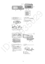
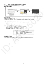
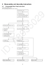
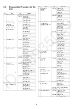
8.3.
Disassembly Procedure for the
Unit
No.
Item
Fig
Removal
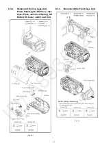
1
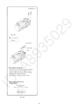
Side Case-L Unit
(Fig. D1) Screw (A) x 3
(Fig. D2) Screw (B) x 1
Locking tab x 3
Hooking part x 3
Side Case-L Unit
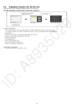
2
Top Case Unit,
Power Panel Light,
LED Piece,
Jack Cover Piece,
Jack Cover Spring,
SS Button, SS Lever,
Jack Cover Unit
(Fig. D3) Screw (C) x 1
Locking tab x 3
Top Case Unit
Power Panel Light
LED Piece
Screw (D) x 1
Convex x 1
Hooking part x 1
Jack Cover Piece
Jack Cover Spring
SS Button
SS Lever
Jack Cover Unit
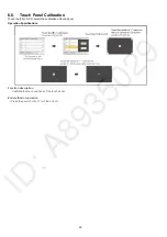
3
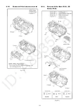
Front Case Unit
(Fig. D4) Screw (E) x 1
Screw (F) x 2
FP6003 (Flex)
Screw (G) x 1
Convex x 2
Front Case Unit
4
Lens Frame Unit
(Fig. D8) Screw (J) x 1
Screw (K) x 1
P6003 (Connector)
Screw (L) x 1
Convex x 2
Locking tab x 2
(Fig. D9) Lens Frame Unit
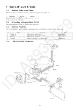
5
Camera Lens Unit
(Fig. D10) FP301 (Flex)
FP6008 (Flex)
Convex x 2
Camera Lens Unit
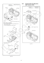
6
Main P.C.B.,
SD Holder P.C.B.
(Fig. D11) Screw (M) x 1
Screw (N) x 3
Screw (O) x 1
Convex x 2
Hooking part x 1
Heat Radiation Plate Unit
P6401 (Connector)
FP6001 (Flex)
FP6402 (Flex)
(Fig. D12) Convex x 5
Locking tab x 4
Bottom Frame Unit
Main P.C.B.
SD Holder P.C.B.
7
Top Operation,
BATT. Catcher P.C.B.
(Fig. D13) Convex x 1
Hooking part x 1
Locking tab x 1
Top Operation
Hooking part x 1
BATT. Catcher P.C.B.
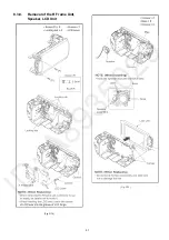
8
R Frame Unit,
Speaker,
LCD Unit
(Fig. D14) Screw (P) x 2
Locking tab x 4
R Frame Unit
Convex x 1
LCD Lever
(Fig. D15) Convex x 2
Convex x 6
Speaker
Convex x 2
LCD Unit
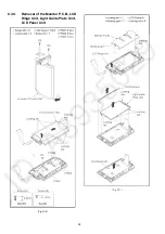
9
Monitor P.C.B.,
LCD Hinge Unit,
Light Guide Plate Unit,
LCD Panel Unit
(Fig. D16) Screw (Q) x 2
Locking tab x 9
LCD Case (T) Unit
Screw (R) x 1
FP901 (Flex)
FP904 (Flex)
FP905 (Flex)
(Fig. D17) Locking tab x 1
Hooking part x 1
Monitor P.C.B.
LCD Hinge Unit
LCD Frame A
Locking tab x 4
Light Guide Plate Unit
LCD Panel Unit
(Fig. D18) Reflection Sheet
Light Guide Plate
Diffusion Sheet
Prism Sheet (B)
Prism Sheet (A)
LGP Holder
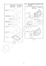
10 Spring Holder,
Barrier Lever
(Fig. D19) Screw (S) x 1
Spring Holder
Barrier Spring
Locking tab x 2
Barrier Lever
11 Front Base,
Barrier R,
Barrier F
(Fig. D20) Projection part x 3
Lens Damper Rubber
Screw (T) x 4
Convex x 3
Front Base
Barrier R
Barrier F
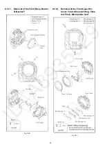
12 Front Case,
Mic Cover,
Front Ornament Ring,
Flare Cut Piece,
Microphone Unit
(Fig. D21) Screw (U) x 2
Locking tab x 1
Front Case
Mic Cover
Front Ornament Ring
Flare Cut Piece
Mic Sponge-F
Mic Sponge-M
Microphone Unit
Mic Sponge-R
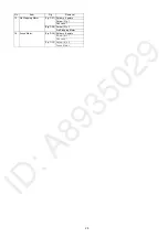
13 MOS Unit,
IR Cut Grass
(Fig. D22) Screw (V) x 3
MOS Unit
MOS Cushion
IR Cut Grass
(Fig. D23) NOTE: (When Installing
the MOS Unit)
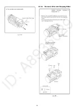
14 2nd Stepping Motor
(Fig. D25) Solder x 16 points
Screw (W) x 3
Convex x 5
(Fig. D26) Screw (X) x 2
2nd Stepping Motor
No.
Item
Fig
Removal
Summary of Contents for HC-V180PP
Page 11: ...11 ...
Page 13: ...13 ...
Page 23: ...23 8 2 PCB Location ...
Page 26: ...26 8 3 1 Removal of the Side Case L Unit Fig D1 Fig D2 ...
Page 28: ...28 8 3 4 Removal of the Lens Frame Unit Fig D8 Fig D9 ...
Page 30: ...30 Fig D12 8 3 7 Removal of the Top Operation BATT Catcher P C B Fig D13 ...
Page 31: ...31 8 3 8 Removal of the R Frame Unit Speaker LCD Unit Fig D14 Fig D15 ...
Page 33: ...33 Fig D18 8 3 10 Removal of the Spring Holder Bar rier Lever Fig D19 ...
Page 35: ...35 8 3 13 Removal of the MOS Unit IR Cut Grass Fig D22 Fig D23 ...
Page 36: ...36 Fig D24 8 3 14 Removal of the 2nd Stepping Motor Fig D25 ...
Page 37: ...37 Fig D26 8 3 15 Removal of the 3rd Stepping Motor Fig D27 ...
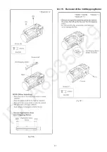
Page 38: ...38 Fig D28 8 3 16 Removal of the Focus Motor Fig D29 ...
Page 39: ...39 Fig D30 ...
Page 43: ...43 9 1 2 Adjustment Items Adjustment item as follows ...
Page 46: ...46 ...
Page 47: ...47 ...
Page 48: ...48 ...
Page 49: ...49 ...
Page 50: ...50 ...
Page 51: ...51 ...