background image

Model No. : HC-V10/V10M/V11M

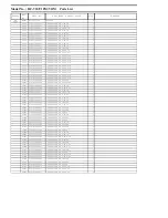
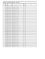
Parts List


Safety

Ref. 

No.

Part No.

Part Name & Description

Q'ty

Remarks


C2002

F3F0J226A016

T.CAPACITOR CH 6.3V 22U

1


C2003

F1G1C104A077

C.CAPACITOR CH 16V 0.1U

1


C2004

F1G0J1050007

C.CAPACITOR CH 6.3V 1U

1


C2005

F1G1E1030005

C.CAPACITOR CH 25V 0.01U

1


C2006

F1G1E1030005

C.CAPACITOR CH 25V 0.01U

1


C2008

F1G0J1050007

C.CAPACITOR CH 6.3V 1U

1


C2011

F1L1A103A016

C.CAPACITOR CH 10V 0.01U

1


C2014

F1L1A103A016

C.CAPACITOR CH 10V 0.01U

1


C2017

F1L1A103A016

C.CAPACITOR CH 10V 0.01U

1


C2020

F1L1A103A016

C.CAPACITOR CH 10V 0.01U

1


C2021

F1L1A103A016

C.CAPACITOR CH 10V 0.01U

1


C2022

F1L1A103A016

C.CAPACITOR CH 10V 0.01U

1


C2023

F1L1A103A016

C.CAPACITOR CH 10V 0.01U

1


C2301

F1L0J1040001

C.CAPACITOR CH 6.3V 0.1U

1


C2304

F1L0J1040001

C.CAPACITOR CH 6.3V 0.1U

1


C2305

F1L0J1040001

C.CAPACITOR CH 6.3V 0.1U

1


C2310

F1G1H8R0A642

C.CAPACITOR CH 50V 8P

1


C2311

F1L1A103A016

C.CAPACITOR CH 10V 0.01U

1


C3401

F3G0J107A011

C.CAPACITOR CH 6.3V 100U

1


C3402

F1H0J4750004

C.CAPACITOR CH 6.3V 4.7U

1


C3403

F1G0J1050007

C.CAPACITOR CH 6.3V 1U

1


C3404

F1G0J1050007

C.CAPACITOR CH 6.3V 1U

1


C3405

F1L0J1040001

C.CAPACITOR CH 6.3V 0.1U

1


C3406

F1G0J1050007

C.CAPACITOR CH 6.3V 1U

1


C3407

F1G0J1050007

C.CAPACITOR CH 6.3V 1U

1


C3408

F1G0J1050007

C.CAPACITOR CH 6.3V 1U

1


C3409

F1J0J106A049

C.CAPACITOR CH 6.3V 10U

1


C3410

F1J0J106A049

C.CAPACITOR CH 6.3V 10U

1


C3411

F3F0J226A016

T.CAPACITOR CH 6.3V 22U

1


C3412

F1J0J106A049

C.CAPACITOR CH 6.3V 10U

1


C3413

F1L0J1040001

C.CAPACITOR CH 6.3V 0.1U

1


C3414

F1G0J1050007

C.CAPACITOR CH 6.3V 1U

1


C3416

F1L0J1040001

C.CAPACITOR CH 6.3V 0.1U

1


C3417

F1L0J1040001

C.CAPACITOR CH 6.3V 0.1U

1


C3418

F1L0J1040001

C.CAPACITOR CH 6.3V 0.1U

1


C3419

F1L0J1040001

C.CAPACITOR CH 6.3V 0.1U

1


C3420

F1L0J1040001

C.CAPACITOR CH 6.3V 0.1U

1


C3421

F1L0J1040001

C.CAPACITOR CH 6.3V 0.1U

1


C3422

F1L0J1040001

C.CAPACITOR CH 6.3V 0.1U

1


C3424

F1L0J1040001

C.CAPACITOR CH 6.3V 0.1U

1


C3425

F1L0J1040001

C.CAPACITOR CH 6.3V 0.1U

1


C3426

F1L0J1040001

C.CAPACITOR CH 6.3V 0.1U

1


C3427

F1L0J1040001

C.CAPACITOR CH 6.3V 0.1U

1


C3429

F1L0J1040001

C.CAPACITOR CH 6.3V 0.1U

1


C3430

F1L0J1040001

C.CAPACITOR CH 6.3V 0.1U

1


C3431

F1G1H120A644

C.CAPACITOR CH 50V 12P

1


C3432

F1G1H8R0A642

C.CAPACITOR CH 50V 8P

1


C3433

F1G0J1050007

C.CAPACITOR CH 6.3V 1U

1


C3434

F1G0J1050007

C.CAPACITOR CH 6.3V 1U

1


C3435

F1J0J106A049

C.CAPACITOR CH 6.3V 10U

1


C3437

F1J0J106A049

C.CAPACITOR CH 6.3V 10U

1


C3438

F1J0J106A049

C.CAPACITOR CH 6.3V 10U

1


C3439

F1G1C104A077

C.CAPACITOR CH 16V 0.1U

1


C3440

F1G1C104A077

C.CAPACITOR CH 16V 0.1U

1


C3441

F1G1H182A640

C.CAPACITOR CH 50V 1800P

1


C3442

F1L0J1040001

C.CAPACITOR CH 6.3V 0.1U

1


C3443

F1L0J1040001

C.CAPACITOR CH 6.3V 0.1U

1


C3444

F1L1A103A016

C.CAPACITOR CH 10V 0.01U

1


C3445

F1L1A103A016

C.CAPACITOR CH 10V 0.01U

1


C3446

F1L0J1040001

C.CAPACITOR CH 6.3V 0.1U

1


C3447

F1L0J1040001

C.CAPACITOR CH 6.3V 0.1U

1


C3448

F1L0J1040001

C.CAPACITOR CH 6.3V 0.1U

1

Summary of Contents for HC-V100MK

Page 1: ...B27 Digital Video Camera Model No HC V10P HC V10PC HC V10PU HC V10EB HC V10EC HC V10EE HC V10EF HC V10EG HC V10EP HC V10GA HC V10GC HC V10GK HC V10GN HC V10GT HC V10GW HC V10MPU HC V11MPU Colour HC V10 K Black Type R Red Type except PC EF GK GN GT GW S Silver Type only P GA GC GK GN HC V10M HC V11M K Black Type ...

Page 2: ...ions 9 5 Location of Controls and Components 11 6 Service Mode 13 6 1 History Display 14 7 Service Fixture Tools 15 7 1 When Replacing the Main P C B 15 7 2 Service Position 15 8 Disassembly and Assembly Instructions 16 8 1 Disassembly Flow Chart for the Unit 16 8 2 PCB Location 16 8 3 Disassembly Procedure for the Unit 17 9 Measurements and Adjustments 24 9 1 Electric Adjustment 24 10 Factory Set...

Page 3: ...exposed to shock hazards 1 2 Leakage Current Cold Check 1 Unplug the AC cord and connect a jumper between the two prongs on the plug 2 Measure the resistance value with an ohmmeter between the jumpered AC plug and each exposed metal lic cabinet part on the equipment such as screwheads connectors control shafts etc When the exposed metal lic part has a return path to the chassis the reading should ...

Page 4: ...ly a grounded tip soldering iron to solder or unsolder ES devices 4 Use only an antistatic solder removal device Some solder removal devices not classified as antistatic ESD protected can generate electrical charge sufficient to damage ES devices 5 Do not use freon propelled chemicals These can generate electrical charges sufficient to damage ES devices 6 Do not remove a replacement ES device from...

Page 5: ...onent Type No ML 614S DN Manufactured by Energy Company Panasonic Corporation It must never be subjected to excessive heat or discharge It must therefore only be fitted in requirement designed specifically for its use Replacement batteries must be of same type and manufacture They must be fitted in the same manner and location as the original battery with the correct polarity contacts observed Do ...

Page 6: ...ld be well molten and mixed with the original lead free solder Remove the remaining lead free solder on the P C B cleanly for soldering of the new IC Since the melting point of the lead free solder is higher than that of the normal lead solder it takes the longer time to melt the lead free solder Use the soldering iron more than 70W equipped with the temperature control after setting the temperatu...

Page 7: ...the INITIAL SETTING data which is stored in Flash ROM mounted on Main P C B 3 4 1 Defining methods To define the model suffix to be serviced refer to the rating label and caution label which are putted on the Unit NOTE After replacing the MAIN P C B be sure to achieve adjustment The adjustment instruction is available at software download on the Support Information from NWBG VDBG AVC web site in T...

Page 8: ...8 3 5 Formatting ...

Page 9: ...9 4 Specifications ...

Page 10: ...10 ...

Page 11: ...D production technology there may be some tiny bright or dark spots on the LCD monitor screen However this is not a malfunction and does not affect the recorded picture 11 Lens cover 12 Lens 13 Lens cover opening closing switch When not using the unit close the lens cover to protect the lens Slide the opening closing switch to open close the cover 14 Internal stereo microphones 15 Menu button MENU...

Page 12: ...Recording Mode Thumbnail display switch Volume lever UVOLT In Playback Mode 26 Speaker 27 Grip belt Adjust the length of the grip belt so that it fits your hand Flip the belt Adjust the length Replace the belt 28 HDMI mini connector 22 23 25 24 27 26 28 Change the mode to recording or playback Operate the mode switch to change the mode to or Selecting a mode Recording Mode Playback Mode ...

Page 13: ... NOTE Do not using service mode except above table of Service mode menu 3 End method of the top screen of the service mode menu Press the MENU button to end the service mode and then POWER OFF Error code Function 51 Focus control is abnormal 52 Zoom control is abnormal 53 OIS lens control is abnormal Screen display Contents Function 1 Factory settings Function to throw a product up in a factory sh...

Page 14: ...n power on and EE state total movie recording time and total number of photo taken They are stored in EEPROM Press MENU button then return to normal recording mode Item Contents PWR Total elapsed time EE Total working time of camera sensor REC SD Movie recorded time of inserted SD card PICT SD Picture recorded number of inserted SD card REC ESD Movie recorded time of internal memory PICT ESD Pictu...

Page 15: ...in TSN system together with Maintenance software 7 2 Service Position This Service Position is used for checking and replacing parts Use the following Extension cables for servicing Table S1 Extension Cable List No Parts No Connection Form 1 VFK1978 FP6001 MAIN MONITOR FPC 31PIN 0 3 FFC 2 VFK1950 PP6008 MAIN LENS UNIT 33PIN 0 3 FFC 3 RFKZ0361 FP301 MAIN MOS UNIT 28PIN 0 5 FFC 4 RFKZ0379 PP6002 MAI...

Page 16: ...16 8 Disassembly and Assembly Instructions 8 1 Disassembly Flow Chart for the Unit This is a disassembling chart When assembling perform this chart conversely 8 2 PCB Location ...

Page 17: ...de L Angle 5 Lens Unit Fig D8 1 Screw G FP301 Flex FP6008 Flex 2 Projection Parts Lens Unit Fig D9 NOTE When Installing 6 SD Holder P C B Fig D10 FP6004 Flex 1 Screw H SD Holder P C B 7 MAIN P C B HC V10 only Fig D11 2 Screws I FP6001 Flex Main P C B 8 MAIN P C B ESD P C B HC V10M V11M only Fig D12 1 Screw J FP6001 Flex 2 Screws K Fig D13 FP6002 Flex Main P C B 2 Screws L ESD P C B 9 LCD Unit Fig ...

Page 18: ...18 Fig D2 8 3 2 Removal of the Rear Top Unit Fig D3 Fig D4 8 3 3 Removal of the Front Case Unit Fig D5 ...

Page 19: ...19 Fig D6 8 3 4 Removal of the Side L Angle Fig D7 8 3 5 Removal of the Lens Unit Fig D8 ...

Page 20: ...20 Fig D9 8 3 6 Removal of the SD Holder P C B Fig D10 ...

Page 21: ...21 8 3 7 Removal of the Main P C B HC V10 only Fig D11 8 3 8 Removal of the Main P C B ESD P C B HC V10M V11M only Fig D12 ...

Page 22: ...22 Fig D13 8 3 9 Removal of the LCD Unit Fig D14 Fig D15 ...

Page 23: ...23 Fig D16 8 3 10 Removal of the Monitor P C B Fig D17 Fig D18 ...

Page 24: ...usive adjustment jig as follows 9 1 1 Adjustment Procedure Install the fully charged battery Connect the main unit to PC with USB The adjustment instruction is available at Software download on the Support Information from NWBG VDBG AVC web site in TSN System Figure of image when adjustment Part Number of jig Only a necessary jig mentions it in setup of electric adjustment No Part Name Part Number...

Page 25: ...25 Adjustment Items Adjustment item as follows The adjustment instruction is available at Software download on the Support Information from NWBG VDBG AVC web site in TSN System ...

Page 26: ...tton 5 After few seconds END is displayed on LCD monitor Press POWER button or cutting of battery connection or AC power supply connection as a completion of the FACTORY SETTINGS NOTE Do not using service mode except above table of Service mode menu End method of the top screen of the service mode menu Push the MENU button to end the service mode and then POWER OFF 10 2 What Is The Factory Setting...

Page 27: ...DIO SIGNAL CLK or CONTROL LINE X3401 OSC 48MHz COLOR LCD PANEL IC3201 INTERNAL MEMORY 16GB HC V10M 32GB HC V11M X2303 32 768kHz IC1503 RTC CHARAGE POWER CONTROL USB TERMINAL IC301 703 704 1011 1421 1441 1471 REGULATOR HC V10 V10M V11M OVERALL BLOCK DIAGRAM HC V10M V11M ONLY IC3402 DDR3 SDRAM 1Gbit A V JACK Analog Analog OPERATION IC2006 SYSTEM CONTROL CAMERA MICROCOMPUTER IC2002 EEPROM X2001 OSC 1...

Page 28: ... SCK GPIOC12 Y1 14 XCE S SENS CS GPIOC9 Y2 22 XCLR E MOS RST CLK60 MOS BUS240 DOAM BUS240 DOAP BUS240 DCKM BUS240 DCKP BUS240 DOBP BUS240 DOBM VD HD SDI SCK SCS SI SYS2 Y11 S SYS2 BS SO SYS2 V11 S SYS2 SB CLK SYS2 W11 E20 AC1 E18 S SYSY2 SCK R0410L 00H V6 R0410L 00H BE REQ2 Y5 BE REQ2 SYS REQ2 Y6 C10 E14 C18 SYS REQ2 COMP BOOT E2 COMP BOOT BE UPDATE U8 BE UPDATE CAM UPDATE W8 E15 E16 C13 CAM UPDAT...

Page 29: ...DR3 SDRAM 1G bit 51 54 11 13 DQ0 DQ15 AD14 DBA1 AD12 DBA0 AA13 ZDRST W8 ODT AD17 K7 K9 J7 J3 K3 L3 L2 M3 N8 M2 T2 K1 DQM0 AA9 DQM1 AC4 AE3 DQSN0 AE4 DQSP0 AE7 DQSN1 AE6 E7 D3 G3 F3 B7 C7 DQSP1 AD10 AC14 N3 N7 DA0 DA12 ADDRESS CTL SIG CTL SIG DATA DATA2 DATA2 DATA1 DATA1 DATA0 DATA0 HPD SCL SDA CEC 5 4 3 6 FL6003 2 3 7 2 1 8 5 6 5 4 3 6 FL6002 8 9 14 7 2 1 8 11 12 15 16 19 JK6003 HDMI CONNECTOR F24...

Page 30: ...12 CH713 CH718 CH719 CH720 15 1 80 S LENS IN S LENS EVRLD S LENS RST L C14 E17 E18 CH721 CH722 CH723 GYRO SENSOR 11 MOSI 44 10 MISO 26 8 CSB CL6401 CL6406 CL6402 CL6403 35 9 SCLK CL6404 1 VCC 7 VDD IC6401 ZOOM ENC ZENC FENC MCLKO FP6008 31 6 30 5 FLEDCONT F ENC Z ENC QR775 ZLEDCONT D20 N4 N1 LENS TEMP C8 LED CONT ZOOM MOTOR FOCUS ENC HC V10 V10M V11M LENS DRIVE CIRCUIT BLOCK DIAGRAM 21 CK27M M FOC...

Page 31: ...IC1503 RTC CHARGE POWER CONTROL VREG32 WKUP F3 B2 USB A1 OUT C2 A3 USBSW G2 VREG25 R1261 Please check the Fuse Resistor when an output voltage does not output IP1502 1 USB TERMINAL VBUS JK6001 IC1441 REGULATOR 3 2 4 1 VIN VOUT STBY GND PW PLL1 1V PW LENS1 5V PW EV6X 1 1V PW 5 4V PW REG1 8V PW SENS1 8V PW DDR1 5V CH1231 CH1421 CH2014 CH1101 ADPSW PWSW A2 ADP C1 VADP SW F2 USB DET E6 E2 E7 BAT E1 VU...

Page 32: ...ATT BATT BATT BATT BATT BATT BATT BATT SPOUT2 SPOUT1 21 22 23 24 25 26 27 28 29 30 31 32 33 34 35 36 37 38 39 40 20 19 18 17 16 15 14 13 12 11 10 9 8 7 6 5 4 3 2 1 FP6002 10 8 6 4 2 VDD GND GND DAT2 DAT0 9 7 5 3 1 VDD CLK CMD DAT1 DAT3 1 2 3 4 5 6 7 8 9 10 11 12 13 14 15 16 17 18 19 20 21 22 23 24 25 26 FP901 PW LCDBL H PW LCDBL L D GND D GND D GND D GND D GND KEYIN BUS9 LCD V BUS9 LCD H PW REG3V ...

Page 33: ...Model No HC V10 V10M V11M Schematic Diagram Note ...

Page 34: ...Model No HC V10 V10M V11M Parts List Note ...

Page 35: ...Model No HC V10 V10M V11M Main Connection Main P C B ...

Page 36: ...Model No HC V10 V10M V11M Video Main P C B ...

Page 37: ...Model No HC V10 V10M V11M Lens Drive Main P C B ...

Page 38: ...Model No HC V10 V10M V11M Syscon Main P C B ...

Page 39: ...Model No HC V10 V10M V11M Charge RTC Main P C B ...

Page 40: ...Model No HC V10 V10M V11M MIC Main P C B ...

Page 41: ...Model No HC V10 V10M V11M Power Main P C B ...

Page 42: ...Model No HC V10 V10M V11M MOS Connection Main P C B ...

Page 43: ...Model No HC V10 V10M V11M SD Holder SD Holder P C B ...

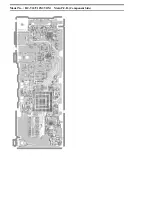
Page 44: ...Model No HC V10 V10M V11M Main P C B Component Side ...

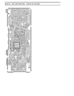
Page 45: ...Model No HC V10 V10M V11M Main P C B Foil Side ...

Page 46: ...Model No HC V10 V10M V11M SD Holder P C B Component Side ...

Page 47: ...Model No HC V10 V10M V11M SD Holder P C B Foil Side ...

Page 48: ... 7U 1 C1101 F1G0J1050007 C CAPACITOR CH 6 3V 1U 1 C1102 F1G1C104A077 C CAPACITOR CH 16V 0 1U 1 C1103 F1G0J1050007 C CAPACITOR CH 6 3V 1U 1 C1161 F1G0J1050007 C CAPACITOR CH 6 3V 1U 1 C1221 F1G0J1050007 C CAPACITOR CH 6 3V 1U 1 C1222 F1J1A106A043 C CAPACITOR CH 10V 10U 1 C1231 F1G0J1050007 C CAPACITOR CH 6 3V 1U 1 C1232 F1J1A106A043 C CAPACITOR CH 10V 10U 1 C1241 F1J1A106A043 C CAPACITOR CH 10V 10U...

Page 49: ...3V 10U 1 C3411 F3F0J226A016 T CAPACITOR CH 6 3V 22U 1 C3412 F1J0J106A049 C CAPACITOR CH 6 3V 10U 1 C3413 F1L0J1040001 C CAPACITOR CH 6 3V 0 1U 1 C3414 F1G0J1050007 C CAPACITOR CH 6 3V 1U 1 C3416 F1L0J1040001 C CAPACITOR CH 6 3V 0 1U 1 C3417 F1L0J1040001 C CAPACITOR CH 6 3V 0 1U 1 C3418 F1L0J1040001 C CAPACITOR CH 6 3V 0 1U 1 C3419 F1L0J1040001 C CAPACITOR CH 6 3V 0 1U 1 C3420 F1L0J1040001 C CAPACI...

Page 50: ...1H220A644 C CAPACITOR CH 50V 22P 1 C6010 F1G1H220A644 C CAPACITOR CH 50V 22P 1 C6011 F1G1H220A644 C CAPACITOR CH 50V 22P 1 C6012 F1G1H220A644 C CAPACITOR CH 50V 22P 1 C6013 F1G1H220A644 C CAPACITOR CH 50V 22P 1 C6014 F1G1H220A644 C CAPACITOR CH 50V 22P 1 C6016 F1L0J1040001 C CAPACITOR CH 6 3V 0 1U 1 C6019 F1L0J1040001 C CAPACITOR CH 6 3V 0 1U 1 C6020 F1G0J1050007 C CAPACITOR CH 6 3V 1U 1 C6021 F1G...

Page 51: ... 3UH 1 L1251 G1C100MA0426 CHIP INDUCTOR 10UH 1 L1261 G1C6R8MA0061 CHIP INDUCTOR 6 8UH 1 L1271 G1C6R8MA0478 CHIP INDUCTOR 6 8UH 1 L1501 G1C4R7ZA0240 CHIP INDUCTOR 4 7UH 1 L3402 G1C100MA0495 CHIP INDUCTOR 10UH 1 L3403 G1C100MA0495 CHIP INDUCTOR 10UH 1 L3404 G1C100MA0408 CHIP INDUCTOR 10UH 1 LB301 J0JBC0000099 FILTER 1 LB3401 J0JBC0000099 FILTER 1 LB3402 J0JBC0000099 FILTER 1 10MPU 11MPU LB6001 J0JCC...

Page 52: ...391 M RESISTOR CH 1 20W 390 1 R793 ERJ1GEJ221 M RESISTOR CH 1 20W 220 1 R1101 ERJ2RKD124 M RESISTOR CH 1 16W 120K 1 R1107 ERJ1GEJ103 M RESISTOR CH 1 20W 10K 1 R1161 ERJ2GEJ200 M RESISTOR CH 1 10W 20 1 R1232 ERJ2RKD474X M RESISTOR CH 1 16W 470K 1 R1233 ERJ2RHD223 M RESISTOR CH 1 16W 22K 1 R1234 ERJ2RKD394 M RESISTOR CH 1 16W 390K 1 R1242 ERJ2RKD334 M RESISTOR CH 1 16W 330K 1 R1243 ERJ2RHD223 M RESI...

Page 53: ...RESISTOR CH 1 10W 10K 1 R2304 ERJ1GEJ102 M RESISTOR CH 1 20W 1K 1 R2312 ERJ2GEJ472 M RESISTOR CH 1 10W 10K 1 R3406 ERJ1GEJ473 M RESISTOR CH 1 20W 47K 1 R3407 ERJ1GEJ473 M RESISTOR CH 1 20W 47K 1 R3408 ERJ1GEJ103 M RESISTOR CH 1 20W 10K 1 R3409 ERJ1GEJ473 M RESISTOR CH 1 20W 47K 1 R3410 ERJ1GEJ473 M RESISTOR CH 1 20W 47K 1 R3411 ERJ2GEJ331 M RESISTOR CH 1 10W 10K 1 R3412 ERJ1GEJ473 M RESISTOR CH 1 ...

Page 54: ...71E392 M RESISTOR CH 1 10W 3 9K 1 R4802 VRE0071E392 M RESISTOR CH 1 10W 3 9K 1 R4803 ERJ6RBD223V M RESISTOR CH 1 10W 22K 1 R4804 JAR0816P104D RESISTOR 1 R4805 VRE0071E472 M RESISTOR CH 1 10W 4 7K 1 R4806 ERJ6RBD223V M RESISTOR CH 1 10W 22K 1 R4807 JAR0816P104D RESISTOR 1 R4808 VRE0071E472 M RESISTOR CH 1 10W 4 7K 1 R4809 ERJ1GEJ472 M RESISTOR CH 1 20W 4 7K 1 R6002 ERJ1GEJ820 M RESISTOR CH 1 20W 82...

Page 55: ...6003 D1H86834A024 RESISTOR NETWORKS 1 10MPU 11MPU S6002 K0H1BA000580 SWITCH 1 S6003 K0H1BA000580 SWITCH 1 S6005 ESE18R12BXFD SWITCH 1 VA301 D4ED16R80001 VARISTOR 1 VA1501 D4ED1270A011 VARISTOR 1 VA1502 D4ED1270A011 VARISTOR 1 VA1503 D4ED18R00008 VARISTOR 1 VA1504 D4ED18R00008 VARISTOR 1 VA4801 D4ED18R00004 VARISTOR 1 VA4802 D4ED18R00004 VARISTOR 1 VA6001 D4EDY1310001 VARISTOR 1 VA6002 D4EDY1310001...

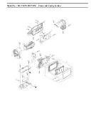
Page 56: ...Model No HC V10 V10M V11M Frame and Casing Section ...

Page 57: ...Model No HC V10 V10M V11M Packing Parts and Accessories Section ...

Page 58: ... 10MPU 13 VEP03J60F ESD P C B UNIT 32GB 1 11MPU 14 VWJ2260 RELAY FFC 1 10MPU 11MPU 301 K2KYYYY00203 AV CABLE 1 302 K2KYYYY00202 USB CABLE 1 303 VSK0784F AC ADAPTOR 1 P PC PU GT 10MPU 11MPU 303 VSK0784G AC ADAPTOR 1 EG EF EC EP GA GW EE 303 VSK0784H AC ADAPTOR 1 EB GC 303 VSK0784J AC ADAPTOR 1 GN 303 VSK0784K AC ADAPTOR 1 GK 304 VFF0899 S CD ROM 1 P PC PU GT EG EF EC EP EB GC GA GW EE GN 10MPU 11MP...

Page 59: ...7866 PACKING CASE UNIT 1 10MPU K 307 VYQ7867 PACKING CASE UNIT 1 11MPU K 308 VPN7361 PAD 1 309 VPF1447 PROTECT BAG 1 P 309 VPF1388 PROTECT BAG 1 EXCEPT P 310 BATTERY PACK 1 P PC K 311 VFF0981 CD ROM O I 1 EG EF EC EP 311 VFF0982 CD ROM O I 1 GC GA GW EE GN 312 LSMF0623 PROTECT SHEET 1 EXCEPT P 313 VQL2C99 OPERATION SHEET 1 PC 313 VQL2D00 OPERATION SHEET 1 GT B1 XQN16 B4FJK SCREW 1 B2 XQN16 B4FJK S...

Reviews: