13
6 Service Mode
1.
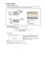
Indication method of the service menu
Set the mode switch “Recording” mode.
2. Turn the power on, and then while keep pressing the “Zoom lever” to W side, “Intelligent auto/Manual” button and “Menu” but-
ton for more than 3 seconds until the top screen of the Service Mode Menu being displayed.
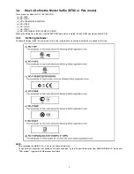
Lock search history indication
• Display the camera system error cord for three histories saved in EEPROM
• The error cord contents which are displayed
Service mode menu
NOTE:
Do not using service mode except above table of Service mode menu.
3. End method of the top screen of the service mode menu
Press the [MENU] button to end the service mode, and then POWER OFF.
Error code
Function
51
Focus control is abnormal
52
Zoom control is abnormal
53
OIS lens control is abnormal
Screen display
Contents
Function
1
Factory settings
Function to throw a product up in a factory shipment state
(Even if recorded data exists in the build-in memory, factory
settings perform the initialization of build-in memory and clear
the history data.)
4
History display
Display accumulated operating time, total recording time and
accumulated number of photos taken.
Summary of Contents for HC-V100MK
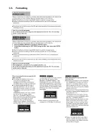
Page 8: ...8 3 5 Formatting ...
Page 9: ...9 4 Specifications ...
Page 10: ...10 ...
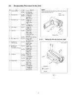
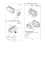
Page 19: ...19 Fig D6 8 3 4 Removal of the Side L Angle Fig D7 8 3 5 Removal of the Lens Unit Fig D8 ...
Page 20: ...20 Fig D9 8 3 6 Removal of the SD Holder P C B Fig D10 ...
Page 22: ...22 Fig D13 8 3 9 Removal of the LCD Unit Fig D14 Fig D15 ...
Page 23: ...23 Fig D16 8 3 10 Removal of the Monitor P C B Fig D17 Fig D18 ...
Page 33: ...Model No HC V10 V10M V11M Schematic Diagram Note ...
Page 34: ...Model No HC V10 V10M V11M Parts List Note ...
Page 35: ...Model No HC V10 V10M V11M Main Connection Main P C B ...
Page 36: ...Model No HC V10 V10M V11M Video Main P C B ...
Page 37: ...Model No HC V10 V10M V11M Lens Drive Main P C B ...
Page 38: ...Model No HC V10 V10M V11M Syscon Main P C B ...
Page 39: ...Model No HC V10 V10M V11M Charge RTC Main P C B ...
Page 40: ...Model No HC V10 V10M V11M MIC Main P C B ...
Page 41: ...Model No HC V10 V10M V11M Power Main P C B ...
Page 42: ...Model No HC V10 V10M V11M MOS Connection Main P C B ...
Page 43: ...Model No HC V10 V10M V11M SD Holder SD Holder P C B ...
Page 44: ...Model No HC V10 V10M V11M Main P C B Component Side ...
Page 45: ...Model No HC V10 V10M V11M Main P C B Foil Side ...
Page 46: ...Model No HC V10 V10M V11M SD Holder P C B Component Side ...
Page 47: ...Model No HC V10 V10M V11M SD Holder P C B Foil Side ...
Page 56: ...Model No HC V10 V10M V11M Frame and Casing Section ...
Page 57: ...Model No HC V10 V10M V11M Packing Parts and Accessories Section ...


