3 CCD Colour Camera Head
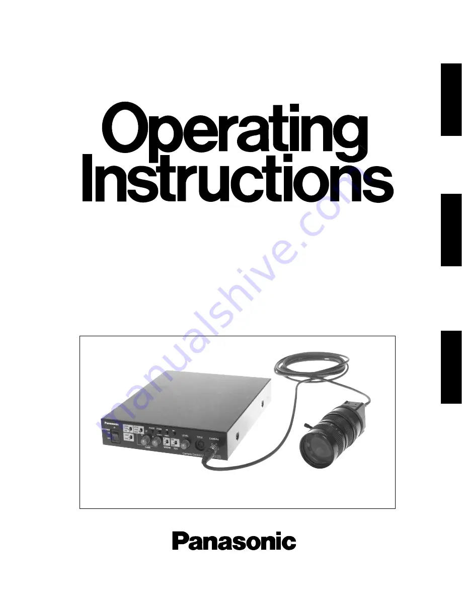
GP-US522HE
GP-US532HE
3 CCD Colour Camera CCU
GP-US522CUE
Lens : Purchased locallyCable : Option
Before attempting to connect or operate this product, please read these instructions completely
DEUTSCH
FRANÇAIS
ENGLISH
Page 1: ...a Head GP US522HE GP US532HE 3 CCD Colour Camera CCU GP US522CUE Lens Purchased locally Cable Option Before attempting to connect or operate this product please read these instructions completely DEUTSCH FRANÇAIS ENGLISH ...
Page 2: ...rovisions of Directive EEC 89 336 Nosotros declaramos bajo nuestra única responsabilidad que el producto a que hace referencia esta declaración està conforme con las normas u otros documentos normativos siguiendo las estipula ciones de la directiva CEE 89 336 Noi dichiariamo sotto nostra esclusiva responsabilità che il prodotto a cui si riferisce la presente dichiarazione risulta conforme ai segue...
Page 3: ...PERATING CONTROLS AND THEIR FUNCTIONS 4 Camera Head 4 Camera Control Unit 4 CONNECTIONS 8 SETUP 10 1 CAMERA SETUP MENU 10 2 SETUP OPERATION 10 SETTING PROCEDURES 12 PREVENTION OF BLOOMING AND SMEAR 21 SPECIFICATIONS 22 OPTIONAL ACCESSORIES 23 1 ENGLISH ...
Page 4: ...h performance micro prism optical system with three 1 2 IT CCDs 2 800 lines of horizontal resolution for GP US522 and 750 lines for GP US532 3 Signal to noise ratio of 60 dB 4 Minimum scene illumination with 18 dB gain of 5 lux at F2 8 for GP US522 and 9 lux at F2 2 for GP US532 5 Auto Tracing White Balance ATW Auto White Balance Control AWC or Manual White Balance Control are selectable 6 Automat...
Page 5: ...g the camera or the camera control unit body Use a dry cloth to clean the camera or the camera control unit when dirty In case the dirt is hard to remove use a mild deter gent and wipe gently 8 Clean the faceplate with care Do not clean the faceplate with strong or abrasive detergents Use lens tissue or a cotton tipped appli cator and ethanol 9 Put the lens cap on the camera after using the camera...
Page 6: ... power of this unit and the power supply for the camera head on or off 5 Power Indicator POWER This indicator lights up red when the power switch is turned on 6 Automatic Manual Gain Selector Switch GAIN HIGH LOW OFF This selector is used to select the gain of the video amplifier as follows The mode can be selected in the SETUP menu Refer to page 15 Camera Control Unit Front Panel MODE SW POSITION...
Page 7: ...ection switch ATW AWC MANU is set to MANU Turn the controls clockwise to increase the red and blue signal levels and counterclockwise to decrease 11 Page Button PAGE This button is used to display the SETUP menu by pressing it for 2 seconds or more and to change the parameters in the SETUP menu 12 Item Button ITEM AWC While the SETUP menu is displayed this button is used to move the cursor downwar...
Page 8: ...gen lock signal Composite Signal Black Burst Signal or Video Sync when either signal is supplied to this connec tor The gen lock signal is used for system reference Caution If the gen lock signal is jittery as in the case of a VTR playback picture the camera cannot be synchronized properly External HD and VD Mode The horizontal and vertical pulse of the colour video signal is synchronized with the...
Page 9: ...ite Video Output 1 0V p p 75 Ω 7 Sync SYNC Output 4 0V p p or 0 3V p p 75 Ω 8 Ground GND 9 Ground GND 26 RS 232C Connector RS 232C Pin No Signal RS 232C Ground TXD RXD DSR Ground DTR CTS RTS Ground 1 2 3 4 5 6 7 8 9 24 S Video Output Connector S VIDEO OUT The luminance Y and chrominance C signals for VTR or monitor are provided at this connector 4 3 2 1 5 1 9 6 Note Refer this connection to a qual...
Page 10: ...tained locally Caution Connect to 12 V DC 11 5 V 16 V class 2 power supply only 3 Connect the power cable between the 12V DC input terminals and the 12V DC power supply unit obtained locally The maximum cable length between camera con trol unit and power supply unit is calculated as fol lows 11 5 V DC VA R x 0 42 x L 16 V DC L Cable length meters R Resistance of copper wire Ω meter VA DC output vo...
Page 11: ...of the optical filter is dirty clean it with a blower brush sold for cleaning camera lenses available at your local camera store 2 Mount the C mount lens by turning it clockwise onto the lens mount of the camera head Cautions Do not use any lens which has more than 1 8 3 5mm of protrusion for lens mounting GP US522 Do not open the lens iris wider than the F2 8 stops GP US522 Do not open the lens i...
Page 12: ...ch time this button is pressed Right Button B This button is used to move the cursor to the right Use this button to select or adjust the parameters of the selected item The parameter changes each time this button is pressed It is described in the following section 2 SETUP OPERATION Note The SETUP menu is output from the VIDEO 1 2 connectors the S VIDEO OUT connector and the RGB SYNC connector SET...
Page 13: ...per formed SET UP CAMERA ID OFF FLD FRM FLD ELC OFF SHUTTER OFF GAIN AUTO SYNC INT BLACK BAL ABC SCENE FILE SCENE1 END SET UP CAMERA ID OFF FLD FRM FLD ELC OFF SHUTTER OFF GAIN AUTO SYNC INT BLACK BAL ABC SCENE FILE SCENE1 END Editing the SETUP menu To edit the SETUP menu change settings press the ITEM button to move the cursor to an item and press A and B to change its parameter After completing ...
Page 14: ... SETTING PROCEDURES SET UP CAMERA ID OFF FLD FRM FLD ELC OFF SHUTTER OFF GAIN AUTO SYNC INT BLACK BAL ABC SCENE FILE SCENE1 END GP US522 ABCDEFGHIJKLM NOPQRSTUVWXYZ 0123456789 ÄÜÖÆÑÅ SPACE POSI RET END RESET Erasing all characters in the editing area Move the character cursor to RESET and press the PAGE button All characters in the editing area disap pear Determining the display position of the CA...
Page 15: ...r and select the desired detection area You can select the detection area as follows ALL All areas on the monitor screen are detected MANU Detection areas are selectable manually See below for details CENTER The photometric weight is given to the centre of the monitor screen S CIRCLE Small Circle The photometric weight is given to the area within a small circle in the centre of the monitor screen ...
Page 16: ... appears 3 1 2 Peak and Average Weight Control PEAK AVE 1 Move the cursor to the PEAK AVE parameter The I cursor starts blinking Note A masked area will be excluded from ELC detection Masked Area WHITE Masked Area WHITE 3 1 1 Manual setting of the ELC detection control area MANU You can mask areas on the monitor screen to block the strong brightness manually Follow the steps below Note The manual ...
Page 17: ...D FRM FLD ELC OFF SHUTTER OFF GAIN AUTO SYNC INT BLACK BAL ABC SCENE FILE SCENE1 END SET UP CAMERA ID OFF FLD FRM FLD ELC OFF SHUTTER MANU GAIN AUTO SYNC INT BLACK BAL ABC SCENE FILE SCENE1 END SHUTTER MANU SET 100 625 RET END 1 Move the cursor to the SHUTTER parameter 2 Select the shutter speed or MANU for manual set ting from the following values 3 If you have selected MANU press the PAGE but to...
Page 18: ...justments When the cable length of the video output or the gen lock input is changed horizontal and subcarrier phase must be readjusted The VS gen lock mode has its own menu for hori zontal and subcarrier phase adjustments When the cable length of the video output or the gen lock input is changed the horizontal phase must be re adjusted When the HD VD or VD pulse is to be used supply them to the V...
Page 19: ...f colour shift Notes When the I cursor reaches the end it jumps back to At the same time SC COARSE is incre mented by one step to enable a continuous adjust ment The reverse takes place when the I cursor reaches the end For more accurate adjustment supply both the original camera video output signal and the effect output video signal program output video signal of the special effects generator SEG...
Page 20: ...ry This setting will not be lost even if the camera con trol unit is turned off However for best results it is recommended that the black balance adjustment be carried out when the camera has not been used for a long period of time There are two black balance control mode Auto black balance control ABC can be selected on the front panel and manual control MANU on this menu 7 1 Auto Black Balance S...
Page 21: ...FILE 2 1 Move the cursor to the SCENE FILE parameter and select SCENE 1 2 Press the PAGE button The SCENE FILE menu appears There are 2 pages for SCENE FILE P1 and P2 On page 1 P1 you can set the following items Gamma Correction GAMMA Auto Knee ON OFF AUTO KNEE Total Pedestal Level Control TOTAL PED Chrominance Level Control CHROMA GAIN Detail Band Control DTL BAND Horizontal Detail Gain Control H...
Page 22: ... I cursor starts blinking 2 While observing the colour video monitor adjust the aperture level Move the I cursor to the side to make the image sharper Move the I cursor to the side to make the image softer When the I cursor is at the end of the side the horizontal detail level is set to OFF 8 7 Vertical Detail Gain Control VDTL GAIN 1 Move the cursor to the VDTL GAIN parameter The I cursor starts ...
Page 23: ...operated carefully in the vicinity of extremely bright objects to avoid smear or blooming If the camera is aimed at the sun or very bright light such as a laser beam for a long period of time the CCD image sensor may be burned in and blemishes white or black dots appears on the monitor screen Bright object Smear PREVENTION OF BLOOMING AND SMEAR Ring type flare ...
Page 24: ...re and gamma Horizontal Resolution 800 lines at centre Y signal GP US522 750 lines at centre Y signal GP US532 White Balance ATW Automatic Tracing White Balance Control AWC Automatic White Balance Control and Manual Black Balance ABC Automatic Black Balance and Manual Colour Bar EBU colour bar with 0 set up Electronic Shutter AUTO Adjustable between 1 50 1 10 000s STEP Selectable between 1 50 OFF ...
Page 25: ... 23 OPTIONAL ACCESSORIES Camera Cable GP CA522 4 Character Generators WJ KB30 WJ KB50 ...
Page 26: ...Matsushita Electric Industrial Co Ltd Central P O Box 288 Osaka 530 91 Japan N1197 1117 YWV8QA4820BN Printed in Japan N 30 Gedruckt in Japan Imprimé au Japon ...