background image


Page 

11

 of 

11


www.FutureElectronics.com


   -   Industrial Wireless IoT solution


Quick Start Guide


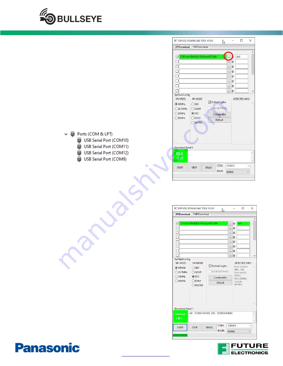
In the first row, click the three dots to select the binary 
file, and the offset 

0x0

, then click the check mark on the 

left to select this file to be programmed. 


Make sure to use the following setting: 

SPI SPEED: 40MHz 
SPI MODE: DIO 
Check the DoNotChgBin option 
BAUD rate: 460800 


When  connecting  the  USB  cable  to  the  Bullseye  USB2 
PGRM  port  (J5),  four  USB  COM  ports  will  be  shown  on 
your PC/Laptop as image example below 


Select  the  second  one  in  regarding  to  the  COM  port 
enumeration number. In the above image example, it is 
the COM10 (which is shown at the beginning) 


Now click START Button at the bottom left of the screen to start programming 


Once programming is completed, press the “RESET” 

button (SW2) on the Bullseye board to reset the Bullseye 
board, and now the Bullseye board is ready to go. 


Summary of Contents for Future Electronics BULLSEYE

Page 1: ...y Part FUT BULLSEYE 0 b 1x Flex PCB Antenna AE3 Part 2108792 1 B Plastic zip bag a 1x Paddle Antenna with cable AE4 Part 2195736 1 2016693 2 Required not included A 1x USB 5V power source and or 1x standard computer USB port with USB micro B cable connector Optional not included for Battery operation A 1x single cell Lithium Battery Cell B 1x USB Type C cable ...

Page 2: ...Page 2 of 11 www FutureElectronics com Industrial Wireless IoT solution Quick Start Guide 2 Bullseye Block Diagram 3 PCB Assembly Details ...

Page 3: ...ctuator PCB attached to the lower left corner of the Bullseye board by twisting up down with your hand or using cutters Fig 2 Place this small actuator board anywhere in between the two guiderails J11 J12 as shown in Fig 2 Fig 1 P8 Jumper Fig 2 Break Out Actuator Board Connect the Flex PCB antenna TE 2108792 1 Fig 3 to connector J3 Connect the Paddle antenna TE 2195736 1 2016693 2 Fig 4 to connect...

Page 4: ... small delay to indicate that the MP2690 s Torch Mode is activated This mode disables its 16sec minimum load power down when load is less than 60mA drawn from the battery while in Boost mode o On power up the Torch mode is toggled ON automatically by the PAN9520 Regular reset will toggle this mode off on o To toggle the Torch mode manually press the Batt Power button SW1 twice within the same seco...

Page 5: ...s sec 5 2 2 Phone or Tablet Connect your device to the WIFI network 2 4Ghz Internet access is required for some of the webpage buttons images Start the Espressif ESPTouch application downloaded in the setup Section 4 3 Select EspTouch in the Main menu Verify SSID name is correct Enter the WIFI network access password Click Start on Android app or Confirm on iPhone App at bottom of screen Close vir...

Page 6: ...fy the SSID name your device is connected to Verify the WIFI network access password Verify the Bullseye board is in pairing mode Blue LED blinking 2times sec If not press the S3 button again to re start the pairing process or press Reset SW2 and then S3 To stop the pairing process at any time press the Reset SW2 button Open an internet browser on a PC connected to the same WIFI network Chrome or ...

Page 7: ...6 2 Antenna Test 6 2 1 Bullseye WiFi Antennas Allows the remote selection one of the four Bullseye s WIFI antennas Select an antenna and perform a WIFI scan by clicking on the WIFI SCAN button on the web page The web page will display the SSID RSSI Channel Security information for each WIFI access point detected with the selected antenna 6 2 2 PAN9520 Embedded Antenna To use the PAN9520 s built in...

Page 8: ...e is 2 inches Note The Web Page refresh rate is set at 0 5 second The refresh rate of the sensor itself can be 50 s to 500 s depending on oversampling setting 6 4 Battery Level Displays live graph of Battery Voltage or Charge Voltage 6 5 Remote Control This page demonstrate remote control function of the PAN9520 via its embedded web page interface The OOB demo firmware allows ON OFF remote control...

Page 9: ... LED will start blinking 2 times sec to indicate 0 inch position calibration step Place the Actuator board on the 0 inch position between the guide rails Leftmost position by lining up the arrows on the Actuator board with the corresponding top and bottom arrow tips on the outside of the two guide rails Press again the User Button S2 once to capture the current voltage for the 0 inch position Gree...

Page 10: ...e follow the steps below 8 1 Firmware Image Download the latest Firmware image from the Future Electronics DC Engine share point site or ask your local Future Electronics representative 8 2 Firmware Download Tool Setup Download the Firmware Download Tool from this link https www espressif com en support download other tools or from the Future Electronics DC Engine share point site This procedure h...

Page 11: ...Bin option BAUD rate 460800 When connecting the USB cable to the Bullseye USB2 PGRM port J5 four USB COM ports will be shown on your PC Laptop as image example below Select the second one in regarding to the COM port enumeration number In the above image example it is the COM10 which is shown at the beginning Now click START Button at the bottom left of the screen to start programming Once program...

Reviews: