13
Ref. No. 1C
Procedure 1A
1B
1C
Removal of housing.
1. Remove nine housing screws.
2. Then open the housing A and B.
NOTE:
When opening the housings, make sure that the main PCB is on the
housing A.
If the main PCB sticks in the housing B and pull it out from the hous-
ing A, the ribbon cable may be defected.
NOTE:
The housing A and B is tightened as themotor mounting base is joint
fitting.
Hold the housing B and take it out vertically.
Ref. No. 1D
Procedure 1A
1B
1C
1D
Removal of ribbon cable.
1. Slightly lift up the connector.
NOTE:
Do not pull the connector firmly because it is not able to take out
completely.
2. Take out the ribbon cable.
Summary of Contents for EYFLA4AR
Page 3: ...3 3 Troubleshooting Guide ...
Page 4: ...4 ...
Page 5: ...5 ...
Page 6: ...6 4 Service Fixture and Adjustment 4 1 Check Parts Identify Procedure ...
Page 7: ...7 ...
Page 8: ...8 ...
Page 24: ...24 7 Wiring Connection Diagram ...
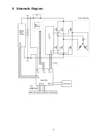
Page 25: ...25 8 Schematic Diagram ...
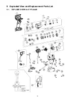
Page 26: ...26 9 Exploded View and Replacement Parts List 9 1 EXPLODED VIEW for EYFLA4AR ...
Page 28: ...28 9 3 EXPLODED VIEW for EYFLA5AR ...
Page 30: ...30 9 5 EXPLODED VIEW for EYFLA5QR ...


