- 20 -
- 22 -
IX
.
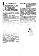
ELECTRICAL PLUG
INFORMATION
FOR YOUR SAFETY PLEASE READ
THE FOLLOWING TEXT CAREFULLY
This appliance is supplied with a moulded
three pin mains plug for your safety and
convenience.
A 5 amp fuse is fitted in this plug.
Should the fuse need to be replaced please
ensure that the replacement fuse has a rat-
ing of 5 amp and that it is approved by ASTA
or BSI to BS1362.
Check for the ASTA mark or the BSI mark
on the body of the fuse.
If the plug contains a removable fuse cover
you must ensure that it is refitted when the
fuse is replaced.
If you lose the fuse cover the plug must not
be used until a replacement cover is ob-
tained.
A replacement fuse cover can be purchased
from your local Panasonic Dealer.
IF THE FITTED MOULDED PLUG IS UN-
SUITABLE FOR THE SOCKET OUTLET IN
YOUR HOME THEN THE FUSE SHOULD
BE REMOVED AND THE PLUG CUT OFF
AND DISPOSED OF SAFELY.
THERE IS A DANGER OF SEVERE ELEC-
TRICAL SHOCK IF THE CUT OFF PLUG IS
INSERTED INTO ANY 13 AMP SOCKET.
If a new plug is to be fitted please observe
the wiring code as shown below.
If in any doubt please consult a qualified
electrician.
IMPORTANT:
The wires in this mains lead
are coloured in accordance
with the following code:
Blue: Neutral
Brown: Live
As the colours of the wire in the mains lead
of this appliance may not correspond with
the coloured markings identifying the termi-
nals in your plug, proceed as follows.
The wire which is coloured BLUE must be
connected to the terminal in the plug which
is marked with the letter N or coloured
BLACK.
The wire which is coloured BROWN must be
connected to the terminal in the plug which is
marked with the letter L or coloured RED.
Under no circumstances should either of
these wires be connected to the earth ter-
minal of the three pin plug, marked with the
letter E or the Earth Symbol .
How to replace the fuse:
Open the fuse
compartment with a screwdriver and replace
the fuse and fuse cover if it is removable.
ONLY FOR U. K.
Fuse Cover
- 20 -
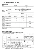
VIII
. SPECIFICATIONS
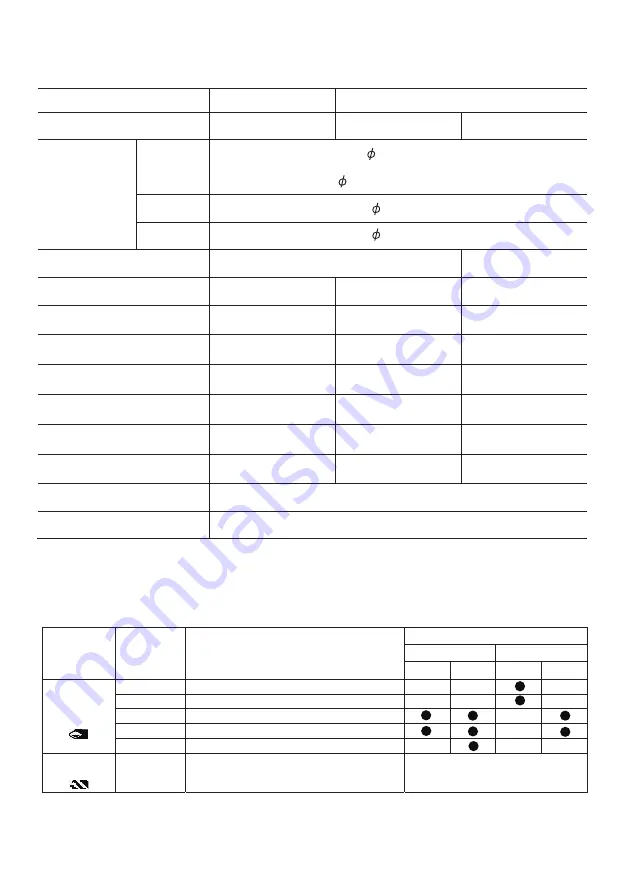
MAIN UNIT
Model
EY7840
EY78A1
Motor voltage
14.4 V DC
14.4 V DC
18 V DC
Maximum drilling
diameter
Concrete
16.5 mm
For work that can be completed with one battery pack
( 12.5 mm - 16.5 mm)
Steel
13 mm
Wood
18 mm
Speed at no load(RPM)
0~1000 rpm
0~1250 rpm
Blows rate per minute(BPM)
3800 bpm
3800 bpm
4750 bpm
Weight
(with battery pack:EY9L45)
2.45 kg
2.45 kg
-
Weight
(with battery pack:EY9L47)
2.25 kg
2.25 kg
-
Weight
(with battery pack:EY9L51)
-
-
-
-
-
-
-
-
2.60 kg
2.35 kg
2.40 kg
2.60 kg
Weight
(with battery pack:EY9L52)
Weight
(with battery pack:EY9L53)
Weight
(with battery pack:EY9L54)
Overall length
249 mm
Noise,Vibration
See the included sheet
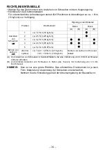
GUIDELINE TABLE
• Select the torque for fastening screws with the clutch handle.
• Guide for the selection of torque
Depending on the job, adjustments are possible in five levels by approximately 1 N·m (10
k
g
f-cm) increments.
Setting
Torque
Guide Depending on Material
Concrete
Block
(A)
(B)
(A)
(B)
Fastening
Screws
1
Approximately 1.5 N·m (15 k
g
f-cm)
2
Approximately 2.5 N·m (25 k
g
f-cm)
3
Approximately 3.4 N·m (35 k
g
f-cm)
4
Approximately 4.4 N·m (45 k
g
f-cm)
5
Approximately 5.4 N·m (55 k
g
f-cm)
Drilling
Holes
(Drill Mark) Approximately 14.4 V: 12.5 N·m (127 k
g
f-cm)
18 V: 13.5 N·m (138 k
g
f-cm)
Drilling holes in wood and metal
(A) For fastening screws into plastic anchor which requires dia. 6.0 mm prehole in the concrete.
(B) For directly fastening screws into concrete (like topcon) with dia. 3.5 mm prehole.
NOTE:
This is only a rough guide. Required torque is different depending on the
shape, material, and application of the screws.
Set according to the work environment of the site.
Summary of Contents for EY78A1LJ2G
Page 154: ... 154 147 MEMO ...
Page 155: ... 155 147 MEMO ...
Page 156: ...EN GR FR IT ND ES DN SW NR FN TR EY971078408 2016 04 F Printed in China ...


