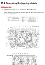
15.3 Removing the tapping shaft
assembly
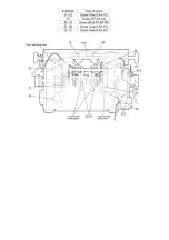
1. Cut all the insulated ties bundling each sensor and lead wires with the aid of a nipper, and
remove the lead wires bundled to the wire saddles (medium, large).
2. Remove all the connectors to the main circuit board.
3. Remove the massage belt, tapping belt, up/down belt and intensity adjustment belt.
4. Remove the intensity sensor set screw A, and remove the intensity sensor.
5. Remove the K type stop ring.
6. Remove the intensity adjustment unit set screws B and C.
7. Remove the fitting part, and remove the intensity adjustment unit.
8. Remove the motor ground wire set screw D.
9. Remove the motor fitting set screws E to H, and remove the motor.
10. Remove the shield panel (fitted to the circuit) set screw and idler pulley set screws I to M, and
remove the shield panel.
11. Remove the motor side guide plate set screws N to U, and remove the motor side guide plate.
When removing the screw Q, take care so that the ground spring is not lost.
12. Remove the idler pulley set screws X and Y, and remove the idler pulley.
13. Remove the eccentric link holding plate set screws V and W with a spanner, and remove the
eccentric link holding plate.
14. In this state the tapping shaft assembly can be removed.
•@
Summary of Contents for EP790-C1
Page 2: ... TOP NEXT ...
Page 4: ... TOP PREVIOUS NEXT ...
Page 8: ... TOP PREVIOUS NEXT ...
Page 10: ... TOP PREVIOUS NEXT ...
Page 15: ...4 1 PARTS IDENTIFICATION TOP PREVIOUS NEXT TOP PREVIOUS NEXT ...
Page 16: ...4 2 TURNING ON THE POWER TOP PREVIOUS NEXT ...
Page 17: ...TOP PREVIOUS NEXT ...
Page 18: ...5 Required tools TOP PREVIOUS NEXT ...
Page 19: ...TOP PREVIOUS NEXT ...
Page 20: ...6 Simplified wiring diagram TOP PREVIOUS NEXT ...
Page 21: ... TOP PREVIOUS NEXT ...
Page 26: ......
Page 32: ... TOP PREVIOUS NEXT ...
Page 35: ... TOP PREVIOUS NEXT ...
Page 39: ... ...
Page 40: ...TOP PREVIOUS NEXT ...
Page 43: ... TOP PREVIOUS NEXT ...
Page 54: ...TOP PREVIOUS NEXT ...
Page 56: ......
Page 57: ... TOP PREVIOUS NEXT ...
Page 61: ...15 7 Assembling TOP PREVIOUS NEXT 15 7 1 Assembling the oval gear TOP PREVIOUS NEXT ...
Page 63: ... TOP PREVIOUS NEXT ...
Page 65: ... TOP PREVIOUS NEXT ...
Page 67: ... TOP PREVIOUS NEXT ...
Page 71: ...TOP PREVIOUS NEXT ...
Page 73: ... TOP PREVIOUS NEXT ...
Page 74: ...16 Arranging massage block lead wires TOP PREVIOUS NEXT ...
Page 75: ...TOP PREVIOUS NEXT ...
Page 76: ...17 Actual wiring diagram TOP PREVIOUS NEXT ...
Page 77: ... TOP PREVIOUS NEXT ...
Page 78: ...18 Trouble shooting TOP PREVIOUS NEXT ...
Page 79: ......
Page 80: ......
Page 81: ......
Page 82: ... TOP PREVIOUS NEXT ...
Page 86: ...19 3 Q A TOP PREVIOUS NEXT TOP PREVIOUS NEXT ...
Page 88: ...20 EXPLODED VIEW TOP PREVIOUS NEXT TOP PREVIOUS NEXT ...
Page 95: ......
Page 96: ......

