background image

9

- For U.S.A. -

FCC STATEMENT:

Note:

This equipment has been tested and found to comply with the limits for a Class B digital device, 
pursuant to Part 15 of the FCC Rules. These limits are designed to provide reasonable protection 
against harmful interference in a residential installation. This equipment generates, uses and can 
radiate radio frequency energy and, if not installed and used in accordance with the instructions, may 
cause harmful interference to radio communications. However, there is no guarantee that 
interference will not occur in a particular installation. If this equipment does cause harmful 
interference to radio or television reception, which can be determined by turning the equipment off 
and on, the user is encouraged to try to correct the interference by one or more of the following 
measures:

Reorient or relocate the receiving antenna.

Increase the separation between the equipment and receiver.

Connect the equipment into an outlet on a circuit different from that to which the receiver is 
connected.

Consult the dealer or an experienced radio / TV technician for help.

FCC Caution:

To assure continued compliance, follow the attached installation instructions and use only shielded 
interface cable with ferrite core when connecting to computer or peripheral devices. Any changes or 
modifications not expressly approved by the party responsible for compliance could void the user’s 
authority to operate this equipment.

Declaration of Conformity
Trade Name: Panasonic

Model No.: 

EJ-CA01UP

Responsible party: Panasonic Corporation of North America

One Panasonic Way, Secaucus, NJ 07094

Support Contact: Panasonic Factory Service Center

Panasonic Service and Technology Company
410B Airport Road
Elgin, IL 60123-9333
Attention: Intraoral Camera

In the USA
FOR SERVICE CALL TOLL FREE
1-800-528-6747

This device complies with Part 15 of the FCC Rules. Operation is subject to the following two 
conditions: (1) this device may not cause harmful interference, and (2) this device must accept any 
interference received, including interference that may cause undesired operation.

EJ-CA01UP&EP_mst.book  9 ページ  2011年4月5日 火曜日 午前10時18分

Summary of Contents for EJCA01UP

Page 1: ...mation thoroughly before attempting to set up and operate the product Compliant with medical safety standards This design complies with the UL 60601 1 and EN 60601 1 safety standards meeting the requirements for use in the medical field Customer s Record The serial number of this product can be found on the Logo sheet of Camera handpiece You should note this serial number in the space provided bel...

Page 2: ...ng to a TV monitor Use the operation button of the Camera handpiece to capture or to playback images There is a 4 split screen that allows multiple still pictures to be displayed simultaneously during playback Note To the customer This product is a medical device and the user must be completely familiar with its operation Read thoroughly each of the items in the Operating Instructions To the deale...

Page 3: ... Fitting Removing the Disposable cover 17 Using with a PC Installing the software 19 Connecting to a PC 22 Starting the software 23 Capturing images on a PC 24 Playing back images on a PC 24 Using with a TV Monitor Connecting to a TV monitor 25 Capturing images on a TV monitor Still pictures only 26 Playing back images on a TV monitor 27 Other Maintenance 28 Troubleshooting 29 Specifications 30 EM...

Page 4: ... a risk that the leakage current may increase If there is anything that you do not understand please contact the dealer where this product was purchased WARNING This indicates content that involves a risk of serious injury or death CAUTION This indicates content that involves a risk of injury or damage to property This indicates content that must NOT be performed This indicates content that MUST b...

Page 5: ...ating for the electrical outlet or wiring device Exceeding the rating by using too many plugs in the same outlet or wiring device could cause a fire due to heat Do not damage the AC cord AC adaptor Camera cable USB cable or Video cable Do not scratch modify put near hot devices forcibly turn twist tug place heavy items upon or knot Using these when damaged could cause fire electric shock or short ...

Page 6: ...e product could cause fire electric shock or product malfunction If water gets inside the product contact your dealer Do not connect or disconnect the power plug with wet hands This could cause electric shock Do not disassemble or modify the product The inside of the product contains high voltage parts that could cause electric shock Order repairs and inspections of the inside of the product from ...

Page 7: ...ugged in could cause insulation degradation short circuiting etc which could cause a fire Do not place the product in an unstable location On an uneven table or an incline etc If the product falls this could cause injury or product malfunction When disposing of this Intraoral Camera you must obey the laws applicable in your area and country and comply with the regulations of your hospital ...

Page 8: ...ctrical damage keep this product away from fluids and chemicals Do not use this product near inadequately shielded medical devices Do not use this product near electromagnetic equipment radio transmitters or high voltage lines For cleaning or storage Please disconnect this product from AC outlet before cleaning Do not use liquid or sprayed detergent for cleaning Use moisture sheet or cloth for cle...

Page 9: ...t into an outlet on a circuit different from that to which the receiver is connected Consult the dealer or an experienced radio TV technician for help FCC Caution To assure continued compliance follow the attached installation instructions and use only shielded interface cable with ferrite core when connecting to computer or peripheral devices Any changes or modifications not expressly approved by...

Page 10: ... product from the lens or button gaps The supplied cords and cables must be used Do not use devices that emit electromagnetic radiation near this product The electromagnetic radiation emitted by communication devices such as mobile phones PHS transceivers etc can affect this device and lead to glitches that cause the product to malfunction In a clinical setting instruct that these communication de...

Page 11: ...lder 1 LSKM2893 AC cord 1 K2CA2YY00116 1 5 m 4 92 ft Unshielded USB cable 1 K1HY04YY0045 Video cable 1 K2KYYYY00065 5 m 16 4 ft Shielded with ferrite core 5 m 16 4 ft Shielded Camera stand 1 LSKM2894 CD ROM 1 LSFT0801 The software and its Operating Instructions Disposable cover 20 sheets 1 LSFB0027 Operating Instructions 1 LSQT1591 Warranty 1 LSQA0243 ...

Page 12: ...of May 2011 Station Kit Model No EJ CK01UP Contents 1 AC adaptor 1 LSEQ0879 2 Cable box 1 LSEQ0884 3 Cable box holder 1 LSKM2893 4 AC cord 1 K2CA2YY00116 5 USB cable 1 K1HY04YY0045 6 Camera stand 1 LSKM2894 7 Operating Instructions 1 LSQT1647 8 Warranty 1 LSQA0248 Disposable Cover Model No EJ CD01UP 200 sheets 1 2 3 4 5 6 7 8 ...

Page 13: ... connected to a PC the MODE button can only switch between Live mode and Special mode Use the PC to switch between record and playback mode For details refer to the software Operating Instructions PDF file When using the product connected to a TV monitor Playback mode displays the captured image P 27 When the mode is switched the corresponding icon is displayed in the upper left of the screen for ...

Page 14: ...ally set to Auto focus right after the power of this product is turned on and right after when the mode is switched to Live mode from Special mode and Playback mode 6 Shutter button This captures still pictures The button is in 2 places top and bottom The button that is easiest to press can be used according to the direction of the lens 7 LED light The light that illuminates what is being captured...

Page 15: ...screw holes of the Cable box holder is 2 mm 0 08 2 places Use this as a reference to select the length of the fastening screw Fasten the Cable box holder where there is enough strength 1 AC adaptor 2 DC cord 3 DC plug 4 AC cord Place the product in the stand when it is not being used Fasten the Camera stand to a wall etc using 2 commercially available screws in the direction as shown in the figure...

Page 16: ...r the BF type applied part according to IEC 60601 1 European Commission Directive 2002 96 EC related to the disposal of electric and electronic devices applies to this product The Class II insulation symbol square within a square indicates that this product has been evaluated and tested to comply with Class II insulation requirements LED light USB terminal DC plug connection terminal of AC adaptor...

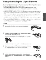
Page 17: ...er that covers the lens with a clean soft cloth such as gauze then use For reasons of hygiene wear gloves when fitting and removing the Disposable cover and dispose of used covers in an appropriate manner When handling a Disposable cover with powdered gloves it may be difficult to fit and remove the cover because the gloves slip Use non slip gloves and powder free gloves Store Disposable covers in...

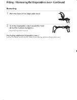
Page 18: ...ch the hem of the Disposable cover 2 Turn the Disposable cover toward the front end of the Camera handpiece Turn the Disposable cover over Purchasing additional Disposable covers Contact the dealer for information related to purchasing additional Disposable covers ...

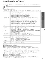
Page 19: ...oft Windows 7 Professional and Service Pack 1 Microsoft Windows 7 Enterprise and Service Pack 1 Microsoft Windows 7 Ultimate and Service Pack 1 Microsoft Windows Vista Home Basic and Service Pack 1 Service Pack 2 Microsoft Windows Vista Home Premium and Service Pack 1 Service Pack 2 Microsoft Windows Vista Ultimate and Service Pack 1 Service Pack 2 Microsoft Windows Vista Business and Service Pack...

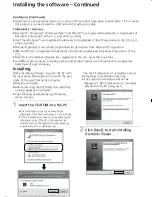
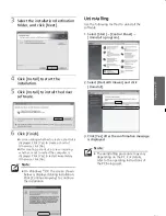
Page 20: ...U S and other countries In addition listed names company names and product names are a trademark or a registered trademark of each company Installing When installing software log onto the PC with the user name Administrator or with the user name of the user that holds computer administrator rights Before inserting the CD ROM close all other running application software The following explanations u...

Page 21: ...estart the computer is displayed Click Yes to restart immediately Otherwise click No Uninstalling Use the following method to uninstall the software 1 Select Start Control Panel Uninstall a program 2 Select Dental i Viewer and click Uninstall 3 Click Yes after the confirmation message is displayed Note On Windows XP the screen shown below is displayed during installation Click Continue Anyway to c...

Page 22: ...er end of the USB cable into a USB terminal on the PC 6 Turn the power to the PC on 7 Press the POWER button on the Camera handpiece to turn the power on Note Connecting to a TV monitor is not available while using the Intraoral Camera with a PC Note Do not connect anything other than the supplied USB cable to the USB terminal of the Cable box On Windows XP when Found New Hardware Wizard screen is...

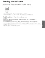
Page 23: ...nstructions Procedure From the start menu select All Programs Programs Panasonic DentaliViewer Operating Instructions For details on how to use the software refer to the software Operating Instructions PDF file Adobe Reader is required in order to read the software Operating Instructions PDF file From the website below download and install the Adobe Reader version that is compatible with the OS th...

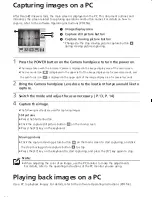
Page 24: ...e mode and adjust focus as necessary P 13 P 14 4 Capture the image The following methods are used for capturing images Playing back images on a PC Use a PC to playback images For details refer to the software Operating Instructions PDF file 1 Image display area 2 Capture still picture button 3 Capture moving picture button Changes to the stop moving picture capture button during moving picture cap...

Page 25: ...VIDEO OUT terminal Connect the other end of the Video cable to the video input terminal yellow terminal of the TV monitor 6 Turn on the power to the TV monitor and switch to external input For details refer to the operating instructions of the TV monitor 7 Press the POWER button on the Camera handpiece to turn the power on Note Connecting to a PC is not available while using the Intraoral Camera w...

Page 26: ... to capture The maximum number of still pictures that can be recorded in the internal memory of the Camera handpiece is 4 If 5 or more images are captured the oldest still picture data is overwritten Note If the Camera handpiece is turned off the still pictures saved in the internal memory are automatically deleted The still pictures are also deleted when the power is turned off by Automatic power...

Page 27: ...image was captured and the number of images saved in the internal memory are displayed in the upper left of the screen for several seconds If only 1 image has been saved the image will not switch even if the LIGHT button is pressed Also even when the MODE button is pressed a 4 split screen will not be displayed and the mode will immediately return to Live mode Images are displayed in a 4 split scr...

Page 28: ...oft cloth that contains a neutral detergent Accessories Other than the Camera stand Wipe with a dry soft cloth At that time remove all connection cables from accessories that are connected to the Camera handpiece PC or TV monitor Remove the power plug of the AC adaptor from the outlet Daily check Check that there are no chips cracks or dirt in the Camera handpiece Camera cable or Camera stand Do n...

Page 29: ...power will automatically turn off Automatic power off Time until the power is turned off automatically is different depending on the status of usage P 13 Moving pictures do not appear on the TV monitor Check that the power plug of the TV monitor is securely inserted all the way to its base into the electrical outlet Check that the Video cable is securely inserted into the Cable box and the TV moni...

Page 30: ...ox 210 g with Camera cable Approx 0 46 lbs Signal system EIA standard NTSC color signal Imaging device 1 6q CCD 680 000 pixels Effective pixels 350 000 pixels Lens 5 group 6 element Auto Iris installed Open F number 4 0 Focal length 2 1 mm 35 mm film equivalent 39 5 mm Focus method auto Video image contrast detection Focus range 0 mm to Live mode Focus method manual Live mode zone focus 3 areas Sp...

Page 31: ...00 V 240 V 50 Hz 60 Hz DC output DC 5 V 1 2 A Input capacitance 0 17 A 0 10 A Dimensions 103 mm k 61 mm k 31 mm length k width k height 4 06q k 2 40q k 1 22q length k width k height Mass Approx 200 g Approx 0 44 lbs DC cord length 3 m 9 8 ft ...

Page 32: ...of the Intraoral Camera Guidance and manufacturer s declaration electromagnetic emissions The Intraoral Camera is intended for use in the electromagnetic environment specified below The customer or the user of the Intraoral Camera should assure that it is used in such an environment Emissions test Compliance Electromagnetic environment guidance RF emissions CISPR 11 Group 1 The Intraoral Camera us...

Page 33: ...IEC 61000 4 5 1 kV line s to line s 2 kV line s to earth 1 kV differential mode 2 kV common mode Mains power quality should be that of a typical commercial or hospital environment Voltage dips short interruptions and voltage variations on power supply input lines IEC 61000 4 11 5 95 dip in for 0 5 cycle 40 60 dip in for 5 cycles 70 30 dip in for 25 cycles 5 95 dip in for 5 sec 5 95 dip in for 0 5 ...

Page 34: ...rom fixed RF transmitters as determined by an electromagnetic site survey a should be less than the compliance level in each frequency range b Interference may occur in the vicinity of equipment marked with the following symbol NOTE 1 At 80 MHz and 800 MHz the higher frequency range applies NOTE 2 These guidelines may not apply in all situations Electromagnetic propagation is affected by absorptio...

Page 35: ...ansmitter W Separation distance according to frequency of transmitter m 150 kHz to 80 MHz d 1 2 80 MHz to 800 MHz d 1 2 800 MHz to 2 5 GHz d 2 3 0 01 0 12 0 12 0 23 0 1 0 38 0 38 0 73 1 1 2 1 2 2 3 10 3 8 3 8 7 3 100 12 12 23 For transmitters rated at a maximum output power not listed above the recommended separation distance d in meters m can be estimated using the equation applicable to the freq...

Page 36: ...the European Union If you wish to discard this product please contact your local authorities or dealer and ask for the correct method of disposal C Panasonic Healthcare Co Ltd 2011 Distributor Panasonic Corporation of North America One Panasonic Way Secaucus NJ 07094 Printed in Japan F0511 0 LSQT1591 ...

Reviews: