background image

5

4 Disassembly and Assembly Instructions

4.1.

Disassembly Instructions

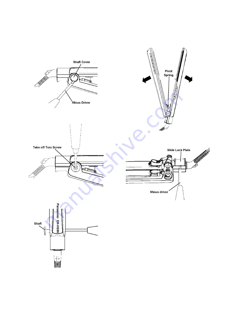
1. Remove Shaft Cover from Main Body by Slotted screw

driver (Minus Driver).

NOTE:

Use NEW Shaft cover once disassembling due to
easily breakage or looseness of hook.

2. Remove Torx screws at Shaft position by Phillips screw

driver (Star Driver).

3. Remove Shaft out by tiny-shaped Phillips screw drivers

and pull it out from the Main body.

4. Remove Pivot spring by gripping and pulling it out from

the Main body.

5. Remove Slide Lock Plate from Main Body by Slotted

screw driver (Minus Driver).

NOTE:

Use NEW Shaft cover once disassembling due to
easily breakage or looseness of hook.

Summary of Contents for EH-HS95

Page 1: ...umber PEWT1311A62CE Household Hair Straightener Model No EH HS95 Asia TABLE OF CONTENTS PAGE PAGE 1 Warning 2 2 Specifications 2 3 Troubleshooting Guide 3 4 Disassembly and Assembly Instructions 5 5 Wiring Connection Diagram 10 6 Schematic Diagram 11 7 Exploded View and Replacement Parts List 12 ...

Page 2: ...ng point is 50 70 F 30 40 C higher Please use a soldering iron with temperature control and adjust it to 750 20 F 400 10 C In case of using high temperature solder ing iron please be careful not to heat too long Pb free solder will tend to splash when heated too high about 1100 F 600 C 2 Specifications ...

Page 3: ...3 3 Troubleshooting Guide Refer to Wiring Connection Diagram ...

Page 4: ...4 ...

Page 5: ...eness of hook 2 Remove Torx screws at Shaft position by Phillips screw driver Star Driver 3 Remove Shaft out by tiny shaped Phillips screw drivers and pull it out from the Main body 4 Remove Pivot spring by gripping and pulling it out from the Main body 5 Remove Slide Lock Plate from Main Body by Slotted screw driver Minus Driver NOTE Use NEW Shaft cover once disassembling due to easily breakage o...

Page 6: ... follow as below drawing When remove Housing A Becareful Floating Spring 4 pcs disappear 8 Take off Iron Plate and Micro PCB Assembly 200C from Housing B Take off Iron Plate from Housing B Slide and take off Iron Plate from Hook Take off Micro PCB Assembly from Housing B by push at Hook of Housing B 9 Remve Tapping Screw from Heater holder B by Philips screw driver Plus Driver ...

Page 7: ...7 10 Take off Iron Plate and High Voltage Igniter PCB Assembly from Press Plate Take off Iron Plate from Press Plate Take off High Voltage Ignitre PCB Assembly from Press Plate ...

Page 8: ...8 4 2 Assembly Instructions 1 Shaft Cover fixing point Have control direction 2 Housing B Assembly Point When insert Power cord must be surely assembly in Connector Cover follow as below ...

Page 9: ... A assembly block and Micro PCB Assembly 200C arrangement follow as below 2 Lead wire of Iron Plate Heater B assembly block and High Voltage Igniter PCB Assembly arrangement follow as below 3 Lead wire of Moisture Assembly Block arrangement follow as below 4 Shaft Cover must be control direction follow as below ...

Page 10: ...10 5 Wiring Connection Diagram ...

Page 11: ...11 6 Schematic Diagram ...

Page 12: ...12 7 Exploded View and Replacement Parts List 7 1 Exploded View All parts are supplied from PMFTH AP through PLAP ...

Page 13: ...PRING 1 13 EHHS95PSW PIVOT SPRING 1 14 EHHS95SLPBW SLIDE LOCK PLATE 1 15 EHHS95SHBW SHAFT 1 16 EHHS95PPBW PRESS PLATE 1 17 EHHS95HBBW HEATER B ASSEMBLY BLOCK 1 18 EHHS952060SW TAPPING SCREW 2 0 6 SILVER 1 19 EHHS95HVCW MOISTURE HV CIRCUIT ASSEMBLY BLOCK 1 INCLUDE 1 ALUMINUM SEAL 20 EHHS95PPC41W PRESS PLATE COVER 1 FOR INDONESIA 20 EHHS95PPC61W PRESS PLATE COVER 1 NO PRINTED nanocare 20 EHHS95PPC62...

Reviews: