4
Federal Communication Commission Interference Statement
This equipment has been tested and found to comply with the limits for a Class B digital device, pursuant to Part 15
of the FCC Rules. These limits are designed to provide reasonable protection against harmful interference in a
residential installation. This equipment generates, uses and can radiate radio frequency energy and, if not installed
and used in accordance with the instructions, may cause harmful interference to radio communications. However,
there is no guarantee that interference will not occur in a particular installation. If this equipment does cause harmful
interference to radio or television reception, which can be determined by turning the equipment off and on, the user
is encouraged to try to correct the interference by one of the following measures:
●
Reorient or relocate the receiving antenna.
●
Increase the separation between the equipment and receiver.
●
Connect the equipment into an outlet on a circuit different from that to which the receiver is connected.
●
Consult the dealer or an experienced radio/TV technician for help.
FCC Caution: Any changes or modifications not expressly approved by the party responsible
for compliance could void the user’s authority to operate this equipment.
This device complies with Part 15 of the FCC Rules. Operation is subject to the following two conditions: (1) This
device may not cause harmful interference, and (2) this device must accept any interference received, including
interference that may cause undesired operation.
For product available in the USA/Canada market, only channel 1~11 can be operated. Selection of other channels is
not possible.
Summary of Contents for EA-7HW02AP1
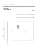
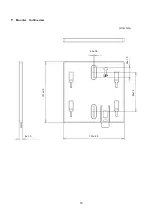
Page 18: ...18 Mounter Outline view Unit mm 24 1 0 84 1 5 4 3 0 5 131 2 5 8 1 0 131 2 5 ...
Page 19: ...19 Stand Outline view 56 2 1 5 122 2 5 66 9 1 5 ...
Page 20: ...20 AC adapter Outline view Unit mm 95 9 1 5 28 5 1 0 43 8 1 5 ...
Page 21: ...21 EA 7HW03AP1 Main unit Outline view Unit mm 38 5 1 5 201 7 2 5 201 7 2 5 ...
Page 22: ...22 Mounter Outline view Unit mm 26 8 1 0 135 2 5 172 5 2 5 117 5 1 5 6 0 5 11 5 1 0 116 2 1 5 ...
Page 55: ...55 Chapter 4 Setting method ...


