29
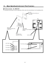
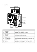
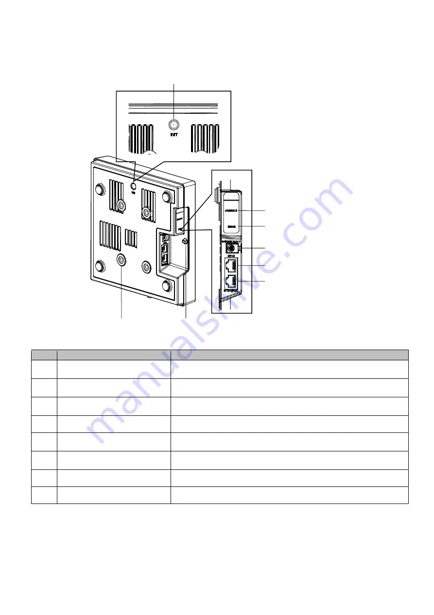
Rear/Left side
No.
Signal
Function
(1)
INIT switch
(Push switch)
Initializes configuration data and log data.
(2)
CONSOLE
(RJ-45 connector)
Connect the console for maintenance, such as a PC.
(3)
MODE 1, 2
(Slide switch)
Not be used. Do not change the default.
(4)
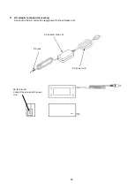
DC IN jack
Connect the DC plug of the provided AC adapter.
(5)
ETH2
(RJ-45 connector)
Connect an Ethernet cable.
(6)
ETH1( PoE) connector
(RJ-45 connector)
Connect an Ethernet cable and start power feeding from a PoE power feeding
equipment.
(7)
Holder
Use this with a cable tie to prevent disconnection of the AC adapter.
(8)
Claw (x4)
Attach by tightening the provided M6 screw when installing on a wall.
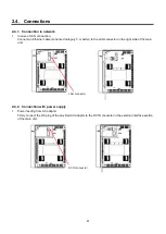
(1) INIT switch
(2) CONSOLE
(3) MODE switch
(4) DC IN jack
(5) ETH2
(6) ETH1 (PoE)
(7) Holder
(8) Claw (x4)
Summary of Contents for EA-7HW02AP1
Page 18: ...18 Mounter Outline view Unit mm 24 1 0 84 1 5 4 3 0 5 131 2 5 8 1 0 131 2 5 ...
Page 19: ...19 Stand Outline view 56 2 1 5 122 2 5 66 9 1 5 ...
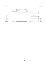
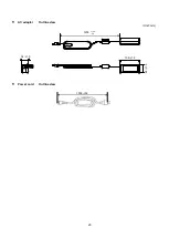
Page 20: ...20 AC adapter Outline view Unit mm 95 9 1 5 28 5 1 0 43 8 1 5 ...
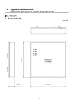
Page 21: ...21 EA 7HW03AP1 Main unit Outline view Unit mm 38 5 1 5 201 7 2 5 201 7 2 5 ...
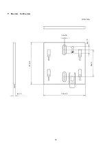
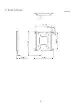
Page 22: ...22 Mounter Outline view Unit mm 26 8 1 0 135 2 5 172 5 2 5 117 5 1 5 6 0 5 11 5 1 0 116 2 1 5 ...
Page 55: ...55 Chapter 4 Setting method ...


