


Do not share the inlet or outlet pipe of Home Shower Unit with
other outlets.
The pressure may drop due to water being drawn off at other point.
The shower water temperature may become very hot.
Avoid using dirty water as it may affect heater performance
and other components.
Make sure no water leaks from pipe connection.
When glue is used for external piping connection, must wait
for the glue to dry before proceed to test run with water.
NOTE:
NOTE:
WARNING
CAUTION
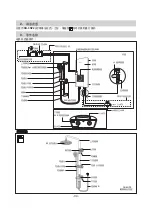
The Filter Body Assembly should be placed in the front direction of the Unit.
Please refer to step (10) Piping installation procedure at page 29
for further.
For DH-3NP2 (with Rain Shower)
Push
Main Body
Thread End
Shower Hose
Parts not
included
Use flexible pipe
minimum length
150 mm
Rubber
Packing
Filter Body
Assembly
Shower
Head
①
②
③
④
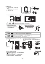
5. Piping installation procedure
For DH3NS1, DH-3NS2, DH-3NP2
③
Place Rubber Packing between Shower Hose and Main Body.
Do not use Piping Tape.
Tighten it by hand firmly.
④
Place Rubber Packing between Shower Hose and Shower Head.
Do not use Piping Tape.
Tighten it by hand firmly.
①
Place Rubber Packing between Filter Body Assembly and Flexible Pipe.
Do not use Piping Tape. Tighten it by Spanner firmly.
②
Place Rubber Packing between Filter Body Assembly and Main Body.
Do not use Piping Tape. Tighten it by hand firmly.
Push
Water Inlet
Water Outlet
Filter Body
Assembly
ELB Test
ELB Reset
Push Up
Push On-Off
Powe
r Control
Off
High
ELB
Note: For the next installation step, please proceed with the respective
model.
• The Unit must be earthed.
• Earth Rod fixing procedure. Select suitable place to bury the optional Earth Rod (DQ-6H) for at least 70 cm below ground surface.
• Ensure that the ground resistance is less than 100 Ω. If it is not, drive the Rod deeper into ground surface or use 2 or 3 Rods.
④
Earth Rod
About 2 m
About 2 m
Ground
Surface
(Parallel Style)
Earth Rod
70 cm at least
70 cm at least
Connection
Burying tool
(Bevel Style) )
70 cm at least
Connection
The Unit must be earthed.
Improper grounding could cause electric shock.
WARNING
①
Make sure the Power Control Knob on Front Plate and it is at “OFF” position.
②
Make sure the “D-Cut” position of the VR Shaft are located as shown.
③
Close the Front Plate of the Unit according to the sequence as illustrated.
④
Push in the Power Control Knob until it is fully insert
<Power Control Knob can not be inserted if Step
①
and Step
②
is
not done accordingly>
⑤
Fix the Screw at the bottom of the Unit.
6. How to fix the Front Plate
“D-Cut”
Position
Back Plate
①
②
Power Control
Knob
Powe
r Control
Off
High
ELB
WARNING
MUST BE
TIGHTENED
L N
Note:
1. Do not push the ELB Test Button during fixing the
Front
Plate.
2. Do not apply extreme force to insert the Power
Control Knob during fixing the Front Plate because
it will damage the switch inside the Unit.
⑤
③
④
Push On-O
ff
Push On-O
ff
Push O
n-Of
f
DH-3NS1
DH-3NS1
DH-3NS1
Screw
Front Plate
Back
Plate
Press
Press
ENGLISH
INST
ALLA
TION
- 27 -