


16
English
CY-VM7203N
17
English
CY-VM7203N
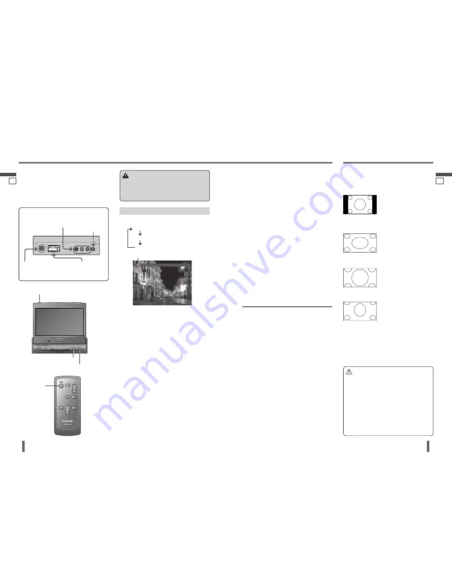
AV/VIDEO 1/VIDEO 2
15
16
AV/VIDEO 1/VIDEO 2
Press
[SRC/PWR]
to change the source.
AV
VIDEO
1
VIDEO
2
You can view the images and listen to the sounds form
the connected external devices (option) in the AV,
VIDEO 1 and VIDEO 2 source respectively.
Preparation:
Connect an optional external device to the unit.
Aspect Ratio
Note:
When the Rear View Camera is in operation with the
transmission gear shift in the reverse position, the
image is shown on the “FULL” screen only.
In some cases, the picture looks different from the
original one due to your selection of aspect.
Default: NORMAL
Mode: 4 types
Press
[ASP] (ASPECT)
on the display unit to change the
aspect ratio as follows.
NORMAL
The conventional display image
has a 4 to 3 ratio of horizontal
to vertical.
In this case, a blank area
remains on the right and left
sides of the display.
FULL
The screen is extended
horizontally as a whole to the
aspect ratio of 16 to 9.
The extension ratio is the same
at any point of the screen.
ZOOM
The screen is fully extended at
the normal aspect ratio of 4 to
3.
The top and bottom of the
screen are slightly cut.
CINEMA
The display is only zoomed
vertically.
The top of the screen will be
cut off, but the bottom will not
be.
Caution
This is to remind you that compression or extension
of the screen using the aspect ratio (screen mode)
changing function of this product for commercial
purpose of profi t making or viewing/listening by
the public could infringe on the rights of the author
protected by the copyright law.
If you expand normal picture (4 to 3) by using
“CINEMA”, “ZOOM” or “FULL” aspect to the full
of the screen, you might not see the periphery of
the picture, or you might see a distorted picture.
Therefore, use the “NORMAL” mode to see the
original pictures as the author intended it.
Preparation:
Specify the correct terminal that is connected to the car
navigation system in the “NAVI INPUT” operation on
the
“User Settings (USER)”
. (page 20)
Press
[NAVI]
to change to the car navigation source.
Press
[NAVI]
again to cancel.
Note:
If the navigation source is ON, only the audio signal is
switched while the video signal remains as it is and the
image is shown on the “FULL” screen only.
The source can be changed even when the display unit
is in the retracted position.
Connecting with Panasonic Car Navigation System
(CN-DV2300N, option):
Connect a Panasonic Car Navigation System to RGB
connector. (page 34)
Car Navigation System
Panasonic TV Tuner (CY-TUP153N,
option)
Select AV source.
Connect a Panasonic TV tuner to AV-IN connectors.
(page 35)
DVD Player/Camcorder
Recommended source: VIDEO 1
Select the same source (VIDEO 1 or VIDEO 2) as the
terminal that is connected to a DVD player or camcorder
(VIDEO 1-IN or VIDEO 2-IN).
Rear View Camera
Recommended source: VIDEO 2
Select the same source (VIDEO 1 or VIDEO 2) as the
terminal that is connected to a Rear View Camera
(VIDEO 1-IN or VIDEO 2-IN).
Execute “CAMERA SETUP” (Rear View Camera Setup)
setting. (page 20)
Source display
Warning
When you connect external devices to Video Input
Terminal (AV-IN/VIDEO 1-IN/VIDEO 2-IN), be sure to
connect the parking brake (side brake) connection
lead. (page 31)
Panasonic Car Navigation System
(CN-DV2300N, option)
See “Car Navigation System” below.
Connect a Panasonic Car Navigation System to RGB
connector. (page 34)
Note:
Car Navigation System (CN-DV2300N, option) is not for
sale in some countries and regions.
Non-Panasonic Car Navigation System
Select the same source (VIDEO 1 or VIDEO 2) as the
terminal that is connected to a Car Navigation System
(VIDEO 1-IN or VIDEO 2-IN).
Execute “NAVI INPUT” (Navigation Input Selection)
setting. (page 20)
[SRC/PWR]
(Source)
[SRC] (PWR)
(Source)
[NAVI]
(Navigation)
[ASP] (ASPECT)
VIDEO 1-IN:
DVD player/receiver
(CQ-D5501N, option)
VIDEO 2-IN:
Rear View Camera
AV-IN:
TV tuner (CY-TUP153N, option)
RGB:
Panasonic Car Navigation System
(CN-DV2300N, option)
Recommended example:


