background image

97 

17.5.2  H12 (Indoor/Outdoor Capacity Rank Mismatched) 

Malfunction Decision Conditions 

  During startup, error code appears when different types of indoor and outdoor units are interconnected. 

 
Malfunction Caused 

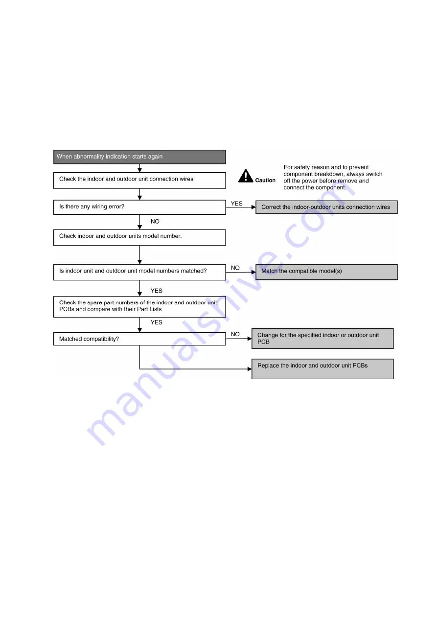
  Wrong models interconnected. 

  Wrong indoor unit or outdoor unit PCBs mounted. 

  Indoor unit or outdoor unit PCBs defective. 

  Indoor-outdoor unit signal transmission error due to wrong wiring. 

  Indoor-outdoor unit signal transmission error due to breaking of wire 3 in the connection wires between the indoor 

and outdoor units. 

 
Troubleshooting 


Summary of Contents for CU-BZ25XKE

Page 1: ...WARNING This service information is designed for experienced repair technicians only and is not designed for use by the general public It does not contain warnings or cautions to advise non technical individuals of potential dangers in attempting to service a product Products powered by electricity should be serviced or repaired only by experienced professional technicians Any attempt to service o...

Page 2: ...zing point 60 13 8 Reference Analysis method for no error code no cooling no warming 66 14 Operation Control 68 14 1 Basic Function 68 14 2 Indoor Fan Motor Operation 69 14 3 Outdoor Fan Motor Operation 70 14 4 Airflow Direction 70 14 5 Timer Control 72 14 6 Sleep Mode Operation 73 14 7 Random Auto Restart Control 74 14 8 Indication Panel 74 14 9 Quiet Operation Cooling Mode Cooling Area of Dry Mo...

Page 3: ... to confirm that no abnormality occurs after the servicing Then explain to user the operation care and maintenance as stated in instructions Please remind the customer to keep the operating instructions for future reference WARNING 1 Do not use means to accelerate the defrosting process or to clean other than those recommended by the manufacturer Any unfit method or using incompatible material may...

Page 4: ...l Current Device RCD with sensitivity of 30mA at 0 1 sec or less Otherwise it may cause electrical shock and fire in case of equipment breakdown or insulation breakdown 20 During installation install the refrigerant piping properly before running the compressor Operation of compressor without fixing refrigeration piping and valves at opened position will cause suck in of air abnormal high pressure...

Page 5: ...or the permanent connection Use an approved 16A 1 0 2 25HP circuit breaker for the permanent connection It must be a double pole switch with a minimum 3 0 mm contact gap 9 Installation or servicing work It may need two people to carry out the installation or servicing work 10 Keep any required ventilation openings clear of obstruction 11 Pb free solder has a higher melting point than standard sold...

Page 6: ...larly check the alarms mechanical ventilation and detectors at least once a year where as required by national regulations to ensure their correct functioning 8 A logbook shall be maintained The results of these checks shall be recorded in the logbook 9 In case of ventilations in occupied spaces shall be checked to confirm no obstruction 10 Before a new refrigerating system is put into service the...

Page 7: ... 2 3 Work procedure Work shall be undertaken under a controlled procedure so as to minimize the risk of a fl ammable gas or vapour being present while the work is being performed 2 4 General work area All maintenance staff and others working in the local area shall be instructed and supervised on the nature of work being carried out Avoid working in confined spaces Always ensure away from source a...

Page 8: ...nals not made to original specification damage to seals incorrect fitting of glands etc Ensure that apparatus is mounted securely Ensure that seals or sealing materials have not degraded such that they no longer serve the purpose of preventing the ingress of flammable atmospheres Replacement parts shall be in accordance with the manufacturer s specifications NOTE The use of silicon sealant may inh...

Page 9: ...en charging and discharging the refrigerant To avoid fire or explosion dissipate static electricity during transfer by grounding and bonding containers and equipment before charging discharging 9 Decommissioning Before carrying out this procedure it is essential that the technician is completely familiar with the equipment and all its details It is recommended good practice that all refrigerants a...

Page 10: ...frigerants In addition a set of calibrated weighing scales shall be available and in good working order Hoses shall be complete with leak free disconnect couplings and in good condition Before using the recovery machine check that it is in satisfactory working order has been properly maintained and that any associated electrical components are sealed to prevent ignition in the event of a refrigera...

Page 11: ...8 30 20 Power Level dB A 53 54 Outdoor Noise H L QLo Pressure Level dB A 48 48 Power Level dB A 64 64 Heating Capacity kW 0 80 3 15 3 60 0 80 3 84 4 40 BTU h 2730 10700 12300 2730 13100 15000 kcal h 690 2710 3100 690 3300 3780 Running Current A 3 50 4 60 Input Power W 190 775 1 04k 195 1 04k 1 29k COP CLASS A A COP W W 4 21 4 06 3 46 4 10 3 69 3 41 BTU hW 14 37 13 81 11 83 14 00 12 60 11 63 kcal h...

Page 12: ... 40 40 Speed Hi Cool rpm 820 860 Heat rpm 820 860 Moisture Removal L h Pt h 1 5 3 2 2 0 4 2 Indoor Airflow QLo Cool m 3 min ft 3 min 4 97 176 4 97 176 Heat m 3 min ft 3 min 6 44 227 6 67 236 Lo Cool m 3 min ft 3 min 7 01 248 8 26 292 Heat m 3 min ft 3 min 7 58 268 9 62 340 Me Cool m 3 min ft 3 min 8 82 312 9 39 332 Heat m 3 min ft 3 min 9 17 324 10 53 372 Hi Cool m 3 min ft 3 min 10 50 370 10 80 3...

Page 13: ...aximum C F 32 89 6 23 73 4 32 89 6 23 73 4 Minimum C F 16 60 8 11 51 8 16 60 8 11 51 8 Heating Maximum C F 30 86 0 30 86 0 Minimum C F 16 60 8 16 60 8 Outdoor Operation Range Cooling Maximum C F 43 109 4 26 78 8 43 109 4 26 78 8 Minimum C F 10 14 0 10 14 0 Heating Maximum C F 24 75 2 18 64 4 24 75 2 18 64 4 Minimum C F 15 5 0 16 3 2 15 5 0 16 3 2 1 Cooling capacities are based on indoor temperatur...

Page 14: ...r Level dB A 60 60 Outdoor Noise H L QLo Pressure Level dB A 48 50 Power Level dB A 63 65 Heating Capacity kW 0 98 5 40 7 50 0 98 6 80 8 00 BTU h 3340 18400 25600 3340 23200 27300 kcal h 840 4640 6450 840 5850 6880 Running Current A 7 10 9 65 Input Power W 210 1 58k 2 45k 230 2 15k 2 65k COP CLASS B D COP W W 4 67 3 42 3 06 4 26 3 16 3 02 BTU hW 15 90 11 65 10 45 14 52 10 79 10 30 kcal hW 4 00 2 9...

Page 15: ...r W 40 40 Speed Hi Cool rpm 820 770 Heat rpm 820 710 Moisture Removal L h Pt h 2 8 5 9 3 3 7 0 Indoor Airflow QLo Cool m 3 min ft 3 min 9 12 322 8 76 309 Heat m 3 min ft 3 min 9 54 337 9 41 332 Lo Cool m 3 min ft 3 min 9 97 352 9 73 344 Heat m 3 min ft 3 min 10 50 371 10 27 363 Me Cool m 3 min ft 3 min 11 24 397 11 24 397 Heat m 3 min ft 3 min 11 77 416 11 99 423 Hi Cool m 3 min ft 3 min 12 50 440...

Page 16: ...Maximum C F 32 89 6 23 73 4 32 89 6 23 73 4 Minimum C F 16 60 8 11 51 8 16 60 8 11 51 8 Heating Maximum C F 30 86 0 30 86 0 Minimum C F 16 60 8 16 60 8 Outdoor Operation Range Cooling Maximum C F 43 109 4 26 78 8 43 109 4 26 78 8 Minimum C F 10 14 0 10 14 0 Heating Maximum C F 24 75 2 18 64 4 24 75 2 18 64 4 Minimum C F 15 5 0 16 3 2 15 5 0 16 3 2 1 Cooling capacities are based on indoor temperatu...

Page 17: ...eters 2 25HP Easy to use remote control Quality Improvement o Random auto restart after power failure for safety restart operation o Gas leakage protection o Prevent compressor reverse cycle o Inner protector to protect compressor Operation Improvement o Quiet mode to reduce the indoor unit operation sound o Powerful mode to reach the desired room temperature quickly Serviceability Improvement o A...

Page 18: ...Vertical airflow direction louver Do not adjust the flap by hand Remote Control receiver Horizontal airflow direction louver Manually adjustable Aluminium fin INDICATOR POWER White TIMER White POWERFUL FAN SPEED QUIET ON OFF TIMER Powerful operation Temperature setting OFF ON Remote control display Operation mode Sleep mode operation Check Clock setting Timer setting Fan speed selection Quiet oper...

Page 19: ...ing hole 497 4 120 115 216 168 115 60 Installation plate Indoor unit external dimensions line PIPE HOLE CENTER 115mm TO HOLE CENTER PIPE HOLE CENTER 115mm TO HOLE CENTER 415 365 16 4 264 4 Unit mm Relative position between the indoor unit and the installation plate Front View 779 Air intake direction Air outlet direction Left piping hole 99 5 55 60 360 41 61 Liquid side Gas side 60 POW ERFUL FAN S...

Page 20: ...as side Low Pressure 2 way valve at Liquid side High Pressure 69 5 18 61 6 542 39 289 22 104 7 60 5 155 2 85 5 34 3 570 104 9 780 67 6 Top View Front View Side View Side View Anchor Bolt Pitch 330 540 Space necessary for installation 100mm 100mm 1000mm Unit mm 6 2 6 4 2 1 2 2 330 619 167 97 32 0 6 1 0 4 5 7 8 6 4 2 8 46 299 3 way valve at Gas side Low Pressure 2 way valve at Liquid side High Press...

Page 21: ...7 7 34 7 131 613 131 2 7 5 7 8 360 5 82 35 Top View Front View Side View Side View Anchor Bolt Pitch 360 5 613 Space necessary for installation 100mm 100mm 1000mm Unit mm 3 way valve at Gas side Low Pressure 2 way valve at Liquid side High Pressure ...

Page 22: ...R TEMP SENSOR AIR TEMP SENSOR COMP TEMP SENSOR PIPE TEMP SENSOR 1 PIPE TEMP SENSOR 2 PIPE TEMP SENSOR LIQUID SIDE 2 WAY VALVE 3 WAY VALVE GAS SIDE COOLING HEAT EXCHANGER EVAPORATOR HEATING COMPRESSOR 4 WAYS VALVE HEAT EXCHANGER CONDENSER MUFFLER MUFFLER FOR BZ25 35 ONLY STRAINER EXPANSION VALVE MUFFLER For BZ25 35 only MUFFLER ...

Page 23: ...SENSOR PIPE TEMP SENSOR AIR TEMP SENSOR LIQUID SIDE 2 WAY VALVE 3 WAY VALVE GAS SIDE COOLING HEAT EXCHANGER EVAPORATOR HEATING COMPRESSOR CONDENSER PROCESS TUBE STRAINER EXPANSION VALVE 4 WAYS VALVE COMP TEMP SENSOR PIPE TEMP SENSOR 1 PIPE TEMP SENSOR 2 RECEIVER ...

Page 24: ... CS BZ35XKE CU BZ35XKE 1 FUSE101 FUSE105 REACTOR FUSE103 FUSE102 RY PWR PTC1 PTC NTC TH1 4 WAYS VALVE RY AC FUSE104 IC19 MS 3 MS 3 RY PWR RY PWR2 FUSE301 TEMP FUSE SC L U M INDOOR UNIT OUTDOOR UNIT SC 2 3 N SINGLE PHASE POWER SUPPLY NOISE FILTER ...

Page 25: ...60XKE 1 FUSE1 RY PWR 4 WAY VALVE Q1 FUSE3 FAN COMPRESSOR MOTOR IC19 MS 3 MS 3 SEN1 RY PWR RY PWR2 FUSE301 TEMP FUSE L U M INDOOR UNIT SC 2 3 N SINGLE PHASE POWER SUPPLY NOISE FILTER RY AC PTC2 PTC FUSE8 FUSE5 FUSE6 REACTOR TH1 NTC SC OUTDOOR UNIT ...

Page 26: ... WHT 1 5 REMOTE CONTROLLER COMPLETE FAN MOTOR AC308 BLK RY PWR RY PWR2 AC307 BRW AC303 WHT AC304 RED G301 GRN EVAPORATOR Y G Y G BL BR W R G TERMINAL BOARD SINGLE PHASE POWER SUPPLY COMMUNICATION CIRCUIT NOISE FILTER CIRCUIT TO OUTDOOR UNIT L N 2 1 3 TEMP FUSE 102 C FUSE301 T3 15A L250V RECTIFICATION CIRCUIT SW01 CN DISP YLW M B BL Y W R 1 5 Y G WITH CORE G Y G EVA REAR VIEW OF TERMINAL BOARD BR W...

Page 27: ... BLU W YLW U V W 3 5 3 1 10 14 16 1 COMP TEMPERATURE SENSOR THERMISTOR 1 3 CN TANK WHT t ELECTRO MAGNETIC COIL 4 WAYS VALVE ELECTRO MAGNETIC COIL EXPANSION VALVE 1 3 CN HOT WHT CN TH WHT 1 6 CN STM WHT P N SWITCHING POWER SUPPLY CIRCUIT FUSE102 T3 15A L250V FUSE103 T3 15A L250V FUSE104 T3 15A L250V FUSE101 20A 250V 3 2 1 COMMUNICATION CIRCUIT PFC CIRCUIT W U V FAN MOTOR ELECTRONIC CONTROLLER MS 3 ...

Page 28: ...Y REACTOR RED BLU YLW YLW YLW U RED FUSE3 T3 15A L250V V BLU W YLW U V W COMPRESSOR TEMP SENSOR THERMISTOR 1 3 CN TANK WHT t 0 ELECTRO MAGNETIC COIL 4 WAYS VALVE 1 3 CN HOT WHT CN TH1 WHT P N 3 5 1 2 3 1 FUSE1 25A 250V 3 2 1 COMMUNICATION CIRCUIT FAN MOTOR ELECTRONIC CONTROLLER MS 3 NOISE FILTER CIRCUIT RED RED OR S TRADE MARK BLUE BLU OR R YELLOW YLW OR C COMP TERMINAL ELECTRO MAGNETIC COIL EXPAN...

Page 29: ...D BR W R BL 12V 12V COM IC03 E 1 2 3 4 16 15 14 13 IC03 IC03 IC03 IC03 5V 5V 12V R90 10K R82 10K F301 L6 L5 C57 0 1µ 16V B1 C56 0 1µ 16V B1 5V C49 NONE C45 0 1µ 16V B1 R37 10k R54 270 5V C48 NONE C47 NONE 5V R85 5 1k R89 NONE 5V C3 0 1µ 16V B1 1 10W 1 10W 4 5 RECEIVER C201 C202 R210 IC201 R201 R202 LED202 white white LED201 1 Vout Vcc GND GND GND 2 3 5V C25 1µ 16V B3 R62 15k 1 C27 1µ 16V B3 R61 20...

Page 30: ... T3 15A L250V V BLU W YLW U V W 3 5 1 10 14 16 P N SWITCHING POWER SUPPLY CIRCUIT FUSE102 T3 15A L250V FUSE103 T3 15A L250V FUSE101 20A 250V 3 2 1 COMMUNICATION CIRCUIT PFC CIRCUIT W U V ELECTRONIC CONTROLLER MS 3 FUSE105 15A 250V NOISE FILTER CIRCUIT RECTIFICATION CIRCUIT RECTIFICATION CIRCUIT 1 3 CN TANK WHITE 5V G8 R209 G8 C207 Q1 CN TH WHITE 5V 1 2 3 4 G6 G8 G6 R206 R205 C205 C204 R208 R207 FA...

Page 31: ...ECTIFICATION CIRCUIT CN TANK 5V G5 R28 4 99k 1 C99 1μ 10V COMP TEMP SENSOR 50kΩ 3950 1 3 t CN TH1 OUTDOOR AIR TEMP SENSOR 15kΩ 3950 1 4 3 2 t t 5V G5 R22 15k 1 R21 15 8k 1 C10 1μ 10V C98 470μ 10V G5 C9 1μ 10V G5 PIPING TEMP SENSOR1 4 96kΩ 3800 CN HOT 4 WAYS VALVE 1 3 2 Q55 D57 D59 R143 S G D A K K A 16V G4A 5V G5 C401 0 1μ 25V ELECTRO MAGNETIC COIL EXPANSION VALVE 6 1 5 4 3 2 M 9 8 CN STM1 15V G4A...

Page 32: ...32 11 Printed Circuit Board 11 1 Indoor Unit 11 1 1 Main Printed Circuit Board G301 AC303 RY PWR AC304 CN STM1 CN RMT CN TH CN CNT JP1 Random Auto Restart enable disable CN DISP CN FM ...

Page 33: ...33 11 1 2 Indicator Receiver Printed Circuit Board CN DISP LED201 LED202 ...

Page 34: ...34 11 2 Outdoor Unit 11 2 1 Main Printed Circuit Board 11 2 1 1 CU BZ25XKE CU BZ35XKE CN HOT CN STM CN TH CN MTR1 CN MTR2 CN TANK POWER TRANSISTOR IPM AC BLK DATA AC WHT ...

Page 35: ...35 11 2 1 2 CU BZ50XKE CU BZ60XKE CN HOT CN MTR1 CN MTR2 CN TH1 CN STM1 CN TANK AC BLK DATA AC WHT POWER TRANSISTOR IPM CURRENT TRANSFORMER CT ...

Page 36: ...r margin formula below Amin mc SF x LFL x h0 The higher value shall be taken when determining the room area 12 1 3 Indoor Outdoor Unit Installation Diagram Model Capacity W HP Piping size Std Length m Max Elevation m Min Piping Length m Max Piping Length m Additional Refrigerant g m Piping Length for add gas m Max Refrigerant Charge kg Indoor Amin m Gas Liquid BZ25 UZ25 PZ25 1 0HP 9 52mm 3 8 6 35m...

Page 37: ...ate horizontally by aligning the marking off line with the thread and using a level gauge 2 Drill the piping plate hole with ø70 mm hole core drill o Line according to the left and right side of the installation plate The meeting point of the extended line is the center of the hole Another method is by putting measuring tape at position as shown in the diagram above The hole center is obtained by ...

Page 38: ...5 mm from the wall CAUTION When the wall is hollow please be sure to use the sleeve for tube assembly to prevent dangers caused by mice biting the connection cable 4 Finish by sealing the sleeve with putty or caulking compound at the final stage 15 mm Putty or caulking compound ø70 mm through hole Indoor Outdoor Sleeve for tube assembly Approx 5 7 mm Bushing for tube assembly Wall ...

Page 39: ...ing and gas leakage confirmation Connect the piping Please refer to Insulation of piping connection column as mentioned in indoor outdoor unit installation Insulate and finish the piping Secure the Indoor Unit Install the Indoor Unit Right Rear piping How to keep the cover In case of the cover is cut keep the cover at the rear of chassis as shown in the illustration for future reinstallation Left ...

Page 40: ...e power supply cord via the left escapement 5 Connection cable between indoor unit and outdoor unit shall be approved polychloroprene sheathed 4 1 5 mm2 1 0 1 5HP or 4 2 5 mm2 2 0 2 25HP flexible cord type designation 60245 IEC 57 or heavier cord 6 Bind all the indoor and outdoor Connection cable with tape and route the connection cable via the right escapement 7 Remove the tapes and connect the p...

Page 41: ...e isolating devices Disconnecting means L N WARNING This equipment must be properly earthed Recommended length mm refer table below Recommended length mm a b c d e f g 30 30 60 45 40 35 55 Isolating Devices Outdoor Unit a b c 4 d e f g 6 1 1 1 Terminal Board Panel Panel Flip the panel down until click sound before connect indoor and outdoor connection cable Holder Holder Flip the panel down Earth ...

Page 42: ...m 5 8 65 N m 6 6 kgf m 19 05 mm 3 4 100 N m 10 2 kgf m A B C D For connection joint of all models Connect the piping Align the center of piping and sufficiently tighten the flare nut with fingers Further tighten the flare but with the torque wrench in specified torque as stated in the table Torque wrench Spanner or Wrench Additional Precautions For R32 Models when connecting by flaring at indoor s...

Page 43: ...he system to reach min 1 04MPa 10 4barg 7 Wait and monitor the pressure reading on the gauges Check if there is any pressure drop Waiting time depends on the size of the system 8 If there is any pressure drop perform step 9 12 If there is no pressure drop perform step 13 9 Use Gas Leak Detector to check for leaks Must use the detection equipment with a sensitivity of 5 grams per year of test gas o...

Page 44: ...lease wrap the insulated piping end to prevent water from going inside the piping 2 If drain hose or connecting piping is in the room where dew may form please increase the insulation by using POLY E FOAM with thickness 6 mm or above 12 3 4 Cutting and Flaring the Piping 1 Please cut using pipe cutter and then remove the burrs 2 Remove the burrs by using reamer If burrs is not removed gas leakage ...

Page 45: ...ever a pep sound is occurred at fifth sec Then press Remote controller A C Reset button once Remote controller signal will activate operation to force heating mode 4 REMOTE CONTROLLER RECEIVING SOUND ON OFF The ON OFF of Remote controller receiving sound can be change over by the following steps a Press AUTO switch continuously for more than 16 sec to below 21 sec A pep pep pep pep sound will occu...

Page 46: ...the unit at cooling heating operation mode for fifteen minutes or more Measure the temperature of the intake and discharge air Ensure the difference between the intake temperature and the discharge is more than 8 C during Cooling operation or more than 14 C during Heating operation Note During extremely cold winter turn on the power supply and standby the unit for at least 15 minutes before test r...

Page 47: ...nditioner o The compressor has a failure history o Oil color is darken ASTM 4 0 and above o The existing air conditioner is gas oil heat pump type Do not reuse the flare to prevent gas leak Make sure to install a new flare If there is a welded part on the existing refrigerant piping conduct a gas leak check on the welded part Replace deteriorated heat insulating material with a new one Heat insula...

Page 48: ...In 2010 the regulations of American Society of Heating Refrigerating and Air Conditioning Engineers in the United States ANSI ASHRAE34 was issued adopting the grades for refrigerants which are difficult to inflame due to their slow burning rates and as a result have smaller damages in cases of fire The burning rate of R32 is lower by 10cm per second and safety standardization for various usage is ...

Page 49: ...e of R410A it is necessary to do installation and service using high pressure tools and components Table 2 Saturated vapor pressure comparison table Unit MPa Temperature Refrigerant R32 R410A R22 20 0 30 0 30 0 14 0 0 71 0 70 0 40 20 1 37 1 35 0 81 40 2 38 2 32 1 43 60 3 84 3 73 2 33 65 4 29 4 17 2 60 Reference Thermal properties table of Japan Society of Refrigerating and Air Conditioning Enginee...

Page 50: ...tools such as screw drivers metal saws electric drills long nose pliers hole core drills ø70 or ø65 linen tape levels temperature gauges clamp meters electric knives nippers pipe cutters reamers or scrapers spring benders diameters 1 4 3 8 1 2 5 8 monkey wrenches fixing wrenches 17 or 12 mm feeler gauges hexagon wrenches 4 mm testers megohm testers etc Tools used for services Works R32 R410A R22 I...

Page 51: ... sizes R32 common R410A R22 Port sizes 1 2 UNF20 7 16 UNF20 5 Charging hoses The pressure resistance of charge hoses is increased At the same time the material is changed to HFC resistant and the size of each manifold adopter is changed as the port size of manifold gauge itself Further some hoses are with anti gas pressure backflow valves placed near the adopters hoses with the valves recommended ...

Page 52: ...ame time the digital scale for refrigerant charging is strengthened by receiving the weight of the refrigerant cylinders with four pillars at the corners The connection ports of charging hoses have two separate ports for R22 7 16 UNF20 and R32 R410A 1 2 UNF20 therefore they can be used for the insertion of the existing refrigerants Digital scale for refrigerant charging 9 Refrigerant cylinders Ref...

Page 53: ...or each HCF type can be used Knowledge for the common usage of tools for R410A R32 R410A and R32 machines use different compressor oils If unregulated compressor oil gets mixed into it may cause damage to the machine function Careful pump down will ensure the recovery of compressor oil and it will minimize the remaining amount of the oil in the manifold gauge and charging hose If you only perform ...

Page 54: ...vention of impurity Leakage checking Insertion of refrigerant Dismantling indoor outdoor units Repairing by brazing Evacuation Air purging new installation and relocation for at or more than 15 minutes re charging at or more than 60 minutes Indoor outdoor units and piping Displacing pipes and wires and displacing indoor outdoor units Indoor outdoor units installation and piping and wiring Removal ...

Page 55: ... of moisture and dirt do not get into the pipes and make sure of no refrigerant leakage The procedure of flaring and precautions a Cutting of pipes use pipe cutter and cut the pipe slowly not to de shape the pipe b Removal of burrs on the edge of pipe reamer or scraper If the condition of pipe edge after the deburring is no good or if burrs attaches on the flaring it may cause refrigerant leakage ...

Page 56: ...nd leave it for 1 2 minutes Then remove the connection side of the charging hose of vacuum pump adopter after checking the needle of manifold gauge does not turn back 4 Open the stem of 2 way valve to 90 in anti clock wise and close the 2 way valve after 10 seconds and perform gas leakage test 5 Remove the charge hose from the service port of 3 way valve and open the stems of 2 way and 3 way valve...

Page 57: ...lectric plug of recovery device into electrical outlet the fan operation starts 6 Turn the valve 1 and 2 of recovery device to pressure equalization point 7 After a few seconds turn back the valve 1 and 2 to the original position 8 Turn the switch of the recovery device to ON the compressor operation starts 9 When the low pressure of manifold gauge is close to 0 close the low pressure side valve t...

Page 58: ...tach and tighten the caps of two way and three way valves with torque wrench 6 Remove the connecting pipes liquid side and gas side b Removal of indoor and outdoor units 1 Remove the connecting pipes and wires between the indoor and outdoor units 2 Attach capping flare nuts on the edges of the pipes connecting the indoor and outdoor units in order to prevent dust and moisture get into the pipes 3 ...

Page 59: ...ures below 6 Remove the charging hose red of the manifold gauge from the vacuum pump adopter 7 After adjusting the digital scale to zero open the cylinder valve and the valve Lo of the manifold gauge and insert the refrigerant 8 If it is not possible to insert the refrigerant at regulated amount at once operate the cooling mode and gradually insert the refrigerant recommended amount approx 150 g 1...

Page 60: ...side check and make sure no refrigerant is contained in the air be careful with vaporized refrigerant Furthermore protect the compressor terminal with metal plates and heat but use wet clothes to cool down releasing the heat the expansion valves and four way valves prevent destruction of parts In brazing it is important to pour the brazing material without melting the base metal based on capillary...

Page 61: ...tly open the oxygen valve of the torch and make sure the gas comes out from the torch crater and then close the oxygen valve Check there is no gas leakage around the hose connection 13 7 4 Adjustment of flame 1 Slightly open the propane valve of the torch and lit with spark lighter This moment the flame is only by propane and the color is red 2 Gradually open the oxygen valve of the torch to mix o...

Page 62: ...mall this has the highest flame heat However due to the excessive oxygen contained in the flame the brazing point gets oxidized This flame may cause holes due to the high heat The pipe may get melt 13 7 6 Closing the flame In case of short break 1 Close the propane valve of the torch 2 Close the oxygen valve of the torch In case of finishing work 1 As above close the flame following the procedure ...

Page 63: ...resistance in stainless steel based brazing suitable for brazing tungsten carbide aluminum bronze and copper BCuP BCuP 2 remain 6 8 7 5 approx 710 approx 785 690 815 21 24 5 Cu Good liquidity suitable for brazing copper tube BCuP 3 4 8 5 2 remain 5 8 6 7 approx 645 approx 815 720 815 21 24 5 Cu Suitable for brazing when the joint spacing is not constant BCuP 5 14 5 15 5 remain 4 8 5 3 approx 645 a...

Page 64: ...n Further by bending the brazing portion of dryer side of the capillary tube at 15 mm from the tube top to the angle of about 120 you can prevent the damage of dryer inside and the clogging of brazing material caused by the excessive insertion of capillary tube 13 7 11 Brazing and heating 1 Place the flame to a pipe which has more heat capacity in order to let the brazing material melt by the pipe...

Page 65: ... capillary tube and dryer etc caution has to be taken to apply the flame to the dryer side thick pipe side in order to prevent burn out by the heat 4 When brazing the compressor connection pipes suction and discharge remove the sound insulation plate and the fan and place the compressor stand vertically to prevent the leakage of compressor refrigerating machine oil and apply the flame from the com...

Page 66: ...an obstructing heat suction 3 Is the setting temperature on the remote controller correct is the setting temperature set at lower higher than the room temperature 13 8 2 Understanding and verification of refrigerant cycle Heat exchanger Heat exchanger Compressor COMP 4 way valve Condenser COND Expansion valve Liquid side 2 way valve Gas side 3 way valve High temp High pressure Air Mid temp High pr...

Page 67: ...ure Excess insertion of refrigerant Clogged capillary expansion valve malfunction Heat releasing obstruction Clog by moisture Dirty condenser attachment of impurity Lack of refrigerant gas Compressor malfunction Operation electric current Excess insertion of refrigerant Lack of refrigerant gas Heat releasing obstruction Compressor malfunction Dirty condenser impurity Mixture of air Insufficient ev...

Page 68: ...tting temperature and it is updated continuously whenever the electrical power is supplied to the unit 14 1 2 Cooling Operation 14 1 2 1 Thermostat control Compressor is OFF when Intake Air Temperature Internal Setting Temperature 1 5 C continue for 3 minutes When compressor is OFF Thermostat OFF and AUTO FAN is set the fan will stop periodically Compressor is ON after waiting for 3 minutes if the...

Page 69: ...e 3 C if previous operate in DRY mode then continue in DRY mode otherwise COOL mode is decided o If 2 C indoor intake temperature remote control setting temperature 3 C maintain with previous mode o If indoor intake temperature remote control setting temperature 2 C HEAT mode is decided 14 2 Indoor Fan Motor Operation 14 2 1 Basic Rotation Speed rpm A Basic Rotation Speed rpm i Manual Fan Speed Co...

Page 70: ...s operation and it stops 30 seconds after compressor stops operation 14 4 Airflow Direction There are two types of airflow vertical airflow directed by horizontal vane and horizontal airflow directed by vertical vanes Control of airflow direction can be automatic angles of direction is determined by operation mode heat exchanger temperature and intake air temperature and manual angles of direction...

Page 71: ...ring fan motor stop When the air conditioner is stopped using remote control the vane will shift to close position 2 Manual vertical airflow direction can be set using remote control the angles of the vane are as stated above and the positions of the vane are as Figure 2 below When the air conditioner is stopped using remote control the vane will shift to close position Side View Inner Vane Closed...

Page 72: ...operate earlier than the setting time This is to provide a comfortable environment when reaching the set ON time 60 minutes before the set time indoor at fan speed of Lo and outdoor fan motor start operate for 30 seconds to determine the indoor intake air temperature and outdoor air temperature in order to judge the operation starting time From the above judgment the decided operation will start o...

Page 73: ...ction will not resume Sleep operation can be set together with Timer operation Sleep operation has priority over OFF Timer Indicator shall be dimmed when this operation is activated Control pattern Cooling mode This operation is incorporated with the activation timer 0 5 1 2 3 4 5 6 7 8 or 9 hours SLEEP Set Speed Set Speed Set Speed Set Speed Set Speed Setting Temperature Setting Fan Speed Selecti...

Page 74: ...the unit are Hot Start during Deice operation operation mode judgment or ON timer sampling If Timer LED is blinking there is an abnormality operation occurs 14 9 Quiet Operation Cooling Mode Cooling Area of Dry Mode A Purpose To provide quiet cooling operation compare to normal operation B Control condition a Quiet operation start condition o When FAN SPEED QUIET button at remote control is presse...

Page 75: ...gain and fan speed is change to Low e Sleep mode timer delay OFF 2 When quiet operation is stopped operation is shifted to normal operation with previous setting 3 When operation mode is changed quiet operation is shifted to quiet operation of the new mode 4 During quiet operation if timer on activates quiet operation maintains 5 After off when on back quiet operation is memorized C Control conten...

Page 76: ... Soft Dry A 5 50 15 03 7 33 15 03 10 23 14 66 12 22 14 66 Cooling Soft Dry B 5 06 6 89 9 69 11 77 Cooling Soft Dry C 5 06 6 89 9 69 11 77 Heating 4 40 5 43 9 41 11 59 4 The first 30 minutes of cooling operation A will be applied 15 1 3 IPM Power transistor Prevention Control Overheating Prevention Control 1 When the IPM temperature rises to 120 C compressor operation will stop immediately 2 Compre...

Page 77: ... C o During Heating operations Indoor piping temperature indoor suction is under 5 C Control contents o Compressor stops and restart after 3 minutes o If the conditions above happen 2 times within 20 minutes the unit will Stop operation Timer LED blinks and F91 indicated 15 1 6 Low Frequency Protection Control 1 When the compressor operate at frequency lower than 24 Hz continued for 20 minutes the...

Page 78: ... high pressure rise protection 15 2 3 Freeze Prevention Control 1 When indoor heat exchanger temperature is lower than 0 C continuously for 6 minutes compressor will stop operating Compressor will resume its operation 3 minutes after the indoor heat exchanger is higher than 5 C At the same time indoor fan speed will be higher than during its normal operation If indoor heat exchanger temperature is...

Page 79: ...pressor OFF Compressor ON The indoor unit fan stops temporarily and then starts to blow at minimum airflow for 30 seconds 2 Compressor ON Compressor OFF The indoor unit fan stops for 90 seconds and then blows at minimum airflow for 20 seconds 15 3 Protection Control for Heating Operation 15 3 1 Intake Air Temperature Control Compressor will operate at limited freq if indoor intake air temperature ...

Page 80: ...r temperature is low deice operation start where indoor fan motor and outdoor fan motor stop and operation LED blinks 15 3 7 Low Pressure Protection Control During low ambient heating operation if the pipe temperature drops below 22 C the max frequency will be reduced and limited If it does not rises after 3 minutes the compressor will stop The compressor will start again if the pipe temperature r...

Page 81: ... 3 REMOTE CONTROL NUMBER SWITCH MODE The Remote Control Number Switch Mode will be activated if the Auto OFF ON button is pressed continuously for more than 11 seconds 3 beep sounds will occur at 11th seconds to identify the Remote Control Number Switch Mode is in standby condition and press AC RESET button and then press any button at remote control to transmit and store the desired transmission ...

Page 82: ...r Old Auto Mode HEAT The unit will run Heating operation The unit will run Heating operation COOL The unit will stop and Power LED blinking The unit will run Cooling operation DRY The unit will stop and Power LED blinking The unit will run Cooling Dry operation NANOE G Stand alone The unit will stop and Power LED blinking The unit will run Nanoe G Stand alone operation Force Cooling The unit will ...

Page 83: ...emote control does not operate for 30 seconds o Press SW special setting is immediately cancelled and normal mode starts o If no SW is pressed for 30 secs then special setting mode is cancelled and normal mode starts o Under this function only and SW s are effective Transmit Remote control no code Normal display mode If jumper JA Open JB Open RC number B If jumper JA Short JB Short RC number C If ...

Page 84: ...ct desired temperature high limit of set temperature for COOL DRY mode Memorize new Low2 range Normal display mode Press SW to enter customer zone Press SW s to choose function 3 Press SW to comfirm selection Use SW or SW to change Low2 range SET i Display latest set temp Low2 ii After reset Low2 16 C by default Range 16 C High2 No code transmission SET Memorize new High2 range Normal display mode...

Page 85: ...ature for HEAT mode o Press Timer Set button to confirm high limit selection Memorize new Low1 range Normal display mode Press SW to enter customer zone Press SW to comfirm selection Use SW or SW to change Low1 range SET i Display latest set temp Low1 ii After reset Low1 16 C by default Range 16 C High1 No code transmission SET Press SW s to choose function 5 Memorize new High1 range Normal displa...

Page 86: ...turns to original display if remote control does not operate for 30 seconds or press Timer Cancel button Memorize new Low3 range Normal display mode Press SW to enter customer zone Press SW to comfirm selection Use SW or SW to change Low3 range SET i Display latest set temp Low3 ii After reset Low3 16 C by default Range 16 C High3 No code transmission SET Press SW s to choose function 12 Memorize ...

Page 87: ...3 RESET AC To restore the unit s setting to factory default o Press once to restore the unit s setting 16 3 4 TIMER To change indoor unit indicator s LED intensity o Press continuously for 5 seconds 16 3 5 TIMER To change remote control display from Degree Celsius C to Degree Fahrenheit F o Press continuously for 10 seconds ...

Page 88: ... Real ON OFF time setting mode 3 To enter Customer zone 4 To enter Service zone Press continuously for T 5 secs POWERFUL FAN SPEED QUIET ON OFF TIMER Customization display area highlighted in color Function No Options If any Customer Zone range 1 49 Normal display mode Once T 5secs Service Zone range 50 99 Customer Zone Normal display mode ...

Page 89: ...status memorize selection 00 Disable 01 Enable 16 49 Reserve Service Zone 50 ECO demo ON None No display 51 Light sensor check None No display 52 nanoe G ECO sensor check None No display 53 DOA check None No display 54 Odor cut control selection 00 Disable 01 Enable 55 Frequency tolerance selection 03 3Hz 07 7Hz 56 Fixed fan speed selection during heat mode compressor OFF 00 Disable 01 Enable 57 n...

Page 90: ...90 Customization Options Remark No Name Service Zone 71 Compressor Fhmax setting selection 01 Offset 1 02 Offset 2 03 Offset 3 72 Compressor Max Fc setting selection 00 Disable 01 Enable 73 99 Reserve ...

Page 91: ...nd a fan The normal outlet air temperature and pressure of the refrigeration cycle depends on various conditions the standard values for them are shown in the table on the right Normal Pressure and Outlet Air Temperature Standard Gas pressure MPa kg cm 2 G Outlet air temperature C Cooling Mode 0 9 1 2 9 12 13 17 Heating Mode 2 0 2 7 20 27 32 42 Condition Indoor fan speed High Outdoor temperature 3...

Page 92: ... current during operation Low Pressure High Pressure Electric current during operation Insufficient refrigerant gas leakage Clogged capillary tube expansion valve or Strainer Short circuit in the indoor unit Heat radiation deficiency of the outdoor unit Inefficient compression Carry out the measurements of pressure electric current and temperature fifteen minutes after an operation is started ...

Page 93: ... CHECK button on the remote controller continuously for 5 seconds 3 will be displayed on the remote controller display Note Display only for No transmitting signal no receiving sound and no Power LED blinking 4 Press the TIMER or button on the remote controller The code H00 no abnormality will be displayed and signal will be transmitted to the main unit The power LED lights up If no abnormality is...

Page 94: ...ality Port is ON for 10s during ion device off ion device PCB H27 Outdoor air temperature sensor abnormality Continuous for 5s Outdoor air temperature sensor open or short circuit Outdoor air temperature sensor lead wire and connector H28 Outdoor heat exchanger temperature sensor 1 abnormality Continuous for 5s Outdoor heat exchanger temperature sensor 1 open or short circuit Outdoor heat exchange...

Page 95: ...zing abnormality 3 times happen within 40 minutes Wrong wiring and connecting pipe expansion valve leakage indoor heat exchanger sensor open circuit Check indoor outdoor connection wire and pipe Indoor heat exchanger sensor lead wire and connector Expansion valve lead wire and connector F90 Power factor correction PFC circuit protection 4 times happen within 10 minutes Power factor correction circ...

Page 96: ...ived from outdoor unit in indoor unit signal transmission is checked whether it is normal Malfunction Caused Faulty indoor unit PCB Faulty outdoor unit PCB Indoor unit outdoor unit signal transmission error due to wiring error Indoor unit outdoor unit signal transmission error due to breaking of wire in the connection wires between the indoor and outdoor units Troubleshooting ...

Page 97: ...are interconnected Malfunction Caused Wrong models interconnected Wrong indoor unit or outdoor unit PCBs mounted Indoor unit or outdoor unit PCBs defective Indoor outdoor unit signal transmission error due to wrong wiring Indoor outdoor unit signal transmission error due to breaking of wire 3 in the connection wires between the indoor and outdoor units Troubleshooting ...

Page 98: ...ction Decision Conditions During startup and operation of cooling and heating the temperatures detected by the indoor intake air temperature sensor are used to determine sensor errors Malfunction Caused Faulty connector connection Faulty sensor Faulty PCB Troubleshooting ...

Page 99: ...n Decision Conditions During startup and operation of cooling and heating the temperatures detected by the outdoor compressor temperature sensor are used to determine sensor errors Malfunction Caused Faulty connector connection Faulty sensor Faulty PCB Troubleshooting ...

Page 100: ...ion Conditions An input current detected by Current Transformer CT is below threshold value when the compressor is operating at certain frequency value for 3 minutes Malfunction Caused Lack of gas Broken CT current transformer Broken Outdoor PCB Troubleshooting ...

Page 101: ...determine abnormal fan motor feedback of rotation 2550rpm or 50rpm Malfunction Caused Operation stops due to short circuit inside the fan motor winding Operation stops due to breaking of wire inside the fan motor Operation stops due to breaking of fan motor lead wires Operation stops due to Hall IC malfunction Operation error due to faulty indoor unit PCB Troubleshooting ...

Page 102: ...ector connection Faulty sensor Faulty PCB Troubleshooting Check the indoor air temperature sensor Is the measure resistance of the indoor intake air temperature sensor matches the value specified in its characteristic chart Plug out connector from the indoor unit PCB Measure the resistance of the indoor intake air temperature sensor Defect in indoor intake air temperature sensor Replace the indoor...

Page 103: ...ction Decision Conditions During startup and operation of cooling and heating the temperatures detected by the outdoor air temperature sensor are used to determine sensor errors Malfunction Caused Faulty connector connection Faulty sensor Faulty PCB Troubleshooting ...

Page 104: ...ction Decision Conditions During startup and operation of cooling and heating the temperatures detected by the outdoor pipe temperature sensor are used to determine sensor errors Malfunction Caused Faulty connector connection Faulty sensor Faulty PCB Troubleshooting ...

Page 105: ...ction Decision Conditions During startup and operation of cooling and heating the temperatures detected by the outdoor discharge pipe temperature sensor are used to determine sensor errors Malfunction Caused Faulty connector connection Faulty sensor Faulty PCB Troubleshooting ...

Page 106: ...unction Decision Conditions During startup and operation of cooling and heating the temperatures detected by the outdoor heat exchanger temperature sensor are used to determine sensor errors Malfunction Caused Faulty connector connection Faulty sensor Faulty PCB Troubleshooting ...

Page 107: ...Malfunction Decision Conditions The supply power is detected for its requirement by the indoor outdoor transmission Malfunction Caused Wrong models interconnected Wrong indoor unit and outdoor unit PCBs used Indoor unit or outdoor unit PCB defective Troubleshooting ...

Page 108: ...nction Decision Conditions During startup and operation of cooling and heating the temperatures detected by the outdoor heat sink temperature sensor are used to determine sensor errors Malfunction Caused Faulty connector connection Faulty sensor Faulty PCB Troubleshooting ...

Page 109: ... Decision Conditions During startup and operation of cooling and heating the temperatures detected by the outdoor gas pipe temperature sensor are used to determine sensor errors Malfunction Caused Faulty connector connection Faulty sensor Faulty PCB Troubleshooting ...

Page 110: ...nction Decision Conditions During startup and operation of cooling and heating the temperatures detected by the outdoor liquid pipe temperature sensor are used to determine sensor errors Malfunction Caused Faulty connector connection Faulty sensor Faulty PCB Troubleshooting ...

Page 111: ...ion Does fan rotate smoothly Turn off power supply and rotate fan by hand Does it rotate YES NO YES Turn off power supply and disconnect fan motor CN MRT2 Check resistance of the motor Measure at fan motor connector CN MRT1 1 2 1 3 2 3 Replace outdoor PCB NO Replace fan motor YES NO U W V Replace fan motor Replace fan motor NO Replace outdoor PCB Stop the fan motor YES Is the resistance normal Che...

Page 112: ...gh pressure is detected when indoor heat exchanger is detecting very high temperature when the unit is operating in heating operation Phenomena unit is stopping and re starting very often in heating mode Malfunction Caused Indoor heat exchanger thermistor Clogged air filter or heat exchanger Over bent pipe liquid side Troubleshooting ...

Page 113: ...l takes place when indoor pipe temperature is lower than 2 C Malfunction Caused Air short circuit at indoor unit Clogged indoor unit air filter Dust accumulation on the indoor unit heat exchanger 2 3 way valve closed Faulty indoor unit fan motor Refrigerant shortage refrigerant leakage Clogged expansion valve or strainer Faulty indoor pipe temperature sensor Faulty indoor unit PCB Troubleshooting ...

Page 114: ... cold during heating except deice or when indoor heat exchanger is hot during cooling and compressor operating the 4 way valve is detected as malfunction Malfunction Caused Indoor heat exchanger pipe thermistor 4 way valve malfunction Troubleshooting Check gas side pipe for hot gas flow in cooling mode ...

Page 115: ...erature and indoor pipe temperature is above 10 C or indoor pipe temperature is below 1 0 C Remark When the indoor standby unit is freezing the outdoor unit transfers F17 error code to the corresponding indoor unit and H39 to other indoor unit s Malfunction Caused Wrong wiring connection Faulty sensor Faulty expansion valve Troubleshooting ...

Page 116: ...startup and operation of cooling and heating when Power Factor Correction PFC protection circuitry at the outdoor unit main PCB senses abnormal DC voltage level for power transistors When DC voltage detected is LOW transistor switching will turn ON by controller to push up the DC level When DC voltage detected is HIGH 391Vdc 425Vdc active LOW signal will send by the controller to turn OFF relay RY...

Page 117: ...frigeration Cycle Abnormality Malfunction Decision Conditions The input current is low while the compressor is running at higher than the setting frequency Malfunction Caused Lack of gas 3 way valve close Troubleshooting ...

Page 118: ...tion Decision Conditions A compressor rotation failure is detected by checking the compressor running condition through the position detection circuit Malfunction Caused Compressor terminal disconnect Faulty Outdoor PCB Faulty compressor Troubleshooting ...

Page 119: ...y the outdoor unit heat exchanger thermistor Malfunction Caused Outdoor heat exchanger temperature rise due to short circuit of hot discharge air flow Outdoor heat exchanger temperature rise due to defective of outdoor fan motor Outdoor heat exchange temperature rise due to defective outdoor heat exchanger thermistor Outdoor heat exchanger temperature rise due to defective of outdoor unit PCB Trou...

Page 120: ...vated o Heat Sink Overheating During operation of cooling and heating when heat sink temperature data 90 C is detected by the heat sink temperature sensor Malfunction Caused IPM overheats due to short circuit of hot discharge air flow IPM overheats due to defective of outdoor fan motor IPM overheats due to defective of internal circuitry of IPM IPM overheats due to defective IPM temperature sensor...

Page 121: ...ling and heating when compressor tank temperature data 112 C is detected by the compressor tank temperature sensor Malfunction Caused Faulty compressor tank temperature sensor 2 3 way valve closed Refrigerant shortage refrigerant leakage Faulty outdoor unit PCB Faulty compressor Troubleshooting ...

Page 122: ...ion of cooling and heating when an input over current X value in Total Running Current Control is detected by checking the input current value being detected by current transformer CT with the compressor running Malfunction Caused Excessive refrigerant Faulty outdoor unit PCB Troubleshooting ...

Page 123: ...heating when inverter DC peak data is received by the outdoor internal DC Peak sensing circuitry Malfunction Caused DC current peak due to compressor failure DC current peak due to defective power transistor s DC current peak due to defective outdoor unit PCB DC current peak due to short circuit Troubleshooting ...

Page 124: ...ectronic Controllers Cross Flow Fan and Indoor Fan Motor Removal Procedures 18 1 1 To Remove Front Grille Figure 1 18 1 2 To Remove Electronic Controller Figure 2 3 Slide the 3 lock knobs on the upside of the Front Grille to unlock position 4 Hold both sides of the Front Grille and remove it by pulling toward yourself gently 1 Lift to open the horizontal vane gently 2 Remove the 3 screws on the Fr...

Page 125: ...all connectors as labelled from the Main Electronic Controller Then pull out the Main Electronic Controller gently 10 Pull out the Main Electronic Controller halfway 7 Detach the CN DISP connector then remove the Indicator Complete 8 Detach the lead wires AC308 Black AC307 Brown AC304 Red and G301 Green from the Terminal Board Figure 3 ...

Page 126: ... Board Figure 7 12 Remove the 2 screws of the Discharge Grille 14 Then pull the Discharge Grille downward gently to dismantle it 13 Pull out and remove the Drain Hose from the Discharge Grille 15 Remove the 4 screws holding the Control Board then pull out the Control Board ...

Page 127: ... Remove Cross Flow Fan and Indoor Fan Motor Figure 8 Figure 9 16 Remove the screw that holding the Cross Flow Fan and Fan Motor axis 18 Remove the Bearing by pulling it gently 17 Remove the screw from the Evaporator ...

Page 128: ...o reinstall the Fan Motor adjust the Fan Motor connector to 60 towards you before fixing Control Board 19 Push the holdfast to the left and lift up the Evaporator 20 Remove the Cross Flow Fan from the unit by pulling it to the left and downward Evaporator Cross Flow Fan Reminder To reinstall the Cross Flow Fan ensure the Cross Flow Fan is in line as shown in figure 11 Cross Flow Fan ...

Page 129: ... Board by 4 hooks Fig 3 5 Remove the Control Board as follows Fig 4 Fig 5 Fig 6 Top Panel Screws Screw Screws Screws Screws Screw Front Panel Hooks Top Cover Hooks Terminal Board Cover Screw Control Board Control Board Release 3 Terminal Connectors L N and Earth Wire Screw Then Remove 4 Terminal Connectors of DRM Remove 2 Screws of Plate Terminal Board Remove of Screw Control Board Release 2 Earth...

Page 130: ... electrostatic discharge 1 Remove the 5 screws of the Top Panel Fig 1 2 Remove the 8 screws of the Front Panel Fig 2 3 Remove the screw of the Terminal Board Cover 4 Remove the Top Cover of the Control Board by 4 hooks Fig 3 5 Remove the Control Board as follows Fig 4 Fig 5 Fig 6 ...

Page 131: ...Controller by 4 hooks Fig 3 5 Remove 2 screws for the plate of Terminal Board Cover Fig 4 6 Remove the Control Board Fig 5 7 Remove the 4 screws of the Electronic Controller Fig 6 Screw Top Panel Screws Screws Screws Screw Screws Front Panel Hooks Screw Terminal Board Cover Hooks Top Cover Screws Plate of Terminal Board Cover Control Board Release screw of Control Board Release 3 terminal connecto...

Page 132: ...1 711 3805 3048 889 3400 2728 1070 22 0 3692 2167 703 4207 2314 876 4238 2314 847 4281 2450 846 4472 2500 715 4203 2402 902 3754 2156 1091 23 15 7 3055 2675 654 3057 2701 656 3405 2835 915 3497 2965 875 3688 3064 709 3476 2947 874 2887 2590 1013 18 4 3393 2179 732 3516 2222 830 3884 2333 792 3752 2355 915 4042 2476 711 3806 2376 885 3295 2162 1060 20 13 3 2615 2395 548 2664 2509 565 2680 2528 550 ...

Page 133: ...74 4077 2012 23 15 7 5530 4777 1111 5449 4849 1245 5168 4692 1028 5024 4642 1068 4846 4510 606 5146 4706 1047 5360 4881 1931 18 4 6558 4287 1716 6757 4450 1549 6635 4402 1557 6474 4324 1637 6768 4483 1122 6609 4385 1605 6029 4155 1972 20 13 3 3883 3869 917 4462 4373 789 3820 3744 838 3984 3978 923 3530 3459 444 3983 3904 762 4078 3997 1236 15 8 5565 3922 1454 5570 3987 1176 5182 3768 1194 5424 391...

Page 134: ... 3609 1043 3753 1049 20 2191 921 2600 1050 3190 1140 3840 1040 4000 1050 16 2117 943 2647 1034 3358 1121 4076 1040 4089 1046 19 2 3 CS BZ50XKE CU BZ50XKE Indoor C Outdoor WB C DB 15 7 2 7 12 TC IP TC IP TC IP TC IP TC IP 24 3620 1891 4181 2103 5290 2109 5058 1574 5384 1566 20 3625 1789 4580 2100 5430 2170 5400 1580 5601 1566 16 3417 1693 4738 2000 5481 2055 5782 1571 5937 1563 19 2 4 CS BZ60XKE CU...

Page 135: ...9 C Cooling Characteristic Fan High Pipe Length 5 0m Freq Rated Fc 20 1 1 CS BZ25XKE CU BZ25XKE Indoor Discharge Air Temperature C Low Pressure MPa Current A Outdoor Air Temperature C Outdoor Air Temperature C Outdoor Air Temperature C 12 16 20 24 28 32 36 40 44 48 12 16 20 24 28 32 36 40 44 48 12 16 20 24 28 32 36 40 44 48 1 00 1 50 2 00 2 50 3 00 3 50 4 00 0 80 0 85 0 90 0 95 1 00 1 05 1 10 1 15...

Page 136: ...re MPa Current A Outdoor Air Temperature C Outdoor Air Temperature C Outdoor Air Temperature C 12 16 20 24 28 32 36 40 44 48 12 16 20 24 28 32 36 40 44 48 12 16 20 24 28 32 36 40 44 48 2 50 3 00 3 50 4 00 4 50 5 00 5 50 6 00 0 80 0 85 0 90 0 95 1 00 1 05 1 10 12 13 14 15 16 17 18 ...

Page 137: ...rent A Low Pressure MPa Indoor Discharge Air Temperature C 12 14 16 18 20 22 24 26 28 30 32 34 36 38 40 42 44 46 48 12 14 16 18 20 22 24 26 28 30 32 34 36 38 40 42 44 46 48 12 14 16 18 20 22 24 26 28 30 32 34 36 38 40 42 44 46 48 2 0 3 0 4 0 5 0 6 0 7 0 8 0 9 0 10 0 0 7 0 8 0 9 1 0 1 1 10 00 11 00 12 00 13 00 14 00 ...

Page 138: ...ssure MPa Indoor Discharge Air Temperature C 12 16 20 24 28 32 36 40 44 48 12 16 20 24 28 32 36 40 44 48 12 16 20 24 28 32 36 40 44 48 3 00 3 50 4 00 4 50 5 00 5 50 6 00 6 50 7 00 7 50 8 00 8 50 9 00 9 50 10 00 0 60 0 65 0 70 0 75 0 80 0 85 0 90 0 95 1 00 1 05 1 10 8 00 9 00 10 00 11 00 12 00 13 00 14 00 15 00 16 00 17 00 18 00 ...

Page 139: ...q Rated Fh 20 2 1 CS BZ25XKE CU BZ25XKE High Pressure MPa Current A Indoor Discharge Air Temperature C Outdoor Air Temperature C Outdoor Air Temperature C Outdoor Air Temperature C 20 15 10 5 0 5 10 15 20 15 10 5 0 5 10 15 20 15 10 5 0 5 10 15 2 00 2 25 2 50 2 75 3 00 3 25 3 50 3 75 4 00 1 50 2 00 2 50 3 00 3 50 15 20 25 30 35 40 45 ...

Page 140: ...t A Indoor Discharge Air Temperature C Outdoor Air Temperature C Outdoor Air Temperature C Outdoor Air Temperature C 20 15 10 5 0 5 10 15 20 15 10 5 0 5 10 15 20 15 10 5 0 5 10 15 2 50 3 00 3 50 4 00 4 50 5 00 5 50 1 00 1 50 2 00 2 50 3 00 3 50 25 30 35 40 45 ...

Page 141: ... Indoor Discharge Air Temperature C Outdoor Air Temperature C Outdoor Air Temperature C Outdoor Air Temperature C 20 15 10 5 0 5 10 15 20 15 10 5 0 5 10 15 20 15 10 5 0 5 10 15 3 0 3 5 4 0 4 5 5 0 5 5 6 0 6 5 7 0 7 5 8 0 1 5 2 0 2 5 3 0 3 5 4 0 25 30 35 40 45 50 ...

Page 142: ...door Discharge Air Temperature C Outdoor Air Temperature C Outdoor Air Temperature C Outdoor Air Temperature C 20 15 10 5 0 5 10 15 20 15 10 5 0 5 10 15 20 15 10 5 0 5 10 15 2 00 2 50 3 00 3 50 4 00 20 25 30 35 40 45 50 55 5 00 6 00 7 00 8 00 9 00 10 00 11 00 12 00 ...

Page 143: ...E CS BZ35XKE CU BZ35XKE Note The graphs show the factor after added right amount of additional refrigerant Cooling Capacity Correction Factor Heating Capacity Correction Factor Pipe Length m Pipe Length m 2 3 4 5 6 7 8 9 10 11 12 13 14 15 16 2 3 4 5 6 7 8 9 10 11 12 13 14 15 16 0 92 0 94 0 96 0 98 1 00 1 02 0 86 0 88 0 90 0 92 0 94 0 96 0 98 1 00 1 02 1 04 ...

Page 144: ...ded right amount of additional refrigerant Cooling Capacity Correction Factor Heating Capacity Correction Factor Pipe Length m Pipe Length m 2 3 4 5 6 7 8 9 10 11 12 13 14 15 16 2 3 4 5 6 7 8 9 10 11 12 13 14 15 16 0 88 0 92 0 96 1 00 1 04 0 98 0 99 0 99 1 00 1 00 1 01 1 01 ...

Page 145: ...dded right amount of additional refrigerant Cooling Capacity Correction Factor Heating Capacity Correction Factor Pipe Length m Pipe Length m 2 4 6 8 10 12 14 16 18 20 22 24 26 28 30 32 2 4 6 8 10 12 14 16 18 20 22 24 26 28 30 32 0 95 0 97 0 99 1 01 1 03 0 98 0 99 1 00 1 01 ...

Page 146: ...bove exploded view is for the purpose of parts disassembly and replacement The non numbered parts are not kept as standard service parts CWH55025J CWH55051AJ 3 2 5 4 33 36 1 20 10 12 7 38 31 8 6 34 18 13 11 14 17 28 32 30 35 29 37 23 25 26 24 27 21 22 19 39 41 40 42 15 9 16 43 ...

Page 147: ...20C05340 20 BACK COVER CHASSIS 1 ACXD93 18680 21 FULCRUM 1 ACXH62 00680 22 VERTICAL VANE 2 ACXE24 03470 23 SHAFT 2 ACXH63 01540 24 SHAFT 2 ACXH63 01570 25 HORIZONTAL VANE INNER 1 ACXE24 03710 26 HORIZONTAL VANE OUTER 1 ACXE24 03720 27 AIR SWING MOTOR 1 ACXA98 02000 O 28 CAP DRAIN TRAY 1 CWH521259 29 REMOTE CONTROL COMPLETE 1 ACXA75C18190 O 30 FRONT GRILLE COMPLETE 1 ACXE10C16420 O 31 INTAKE GRILLE...

Page 148: ...MPLETE 1 ACXE20C05330 20 BACK COVER CHASSIS 1 ACXD93 18680 21 FULCRUM 1 ACXH62 00680 22 VERTICAL VANE 2 ACXE24 03470 23 SHAFT 2 ACXH63 01540 24 SHAFT 2 ACXH63 01570 25 HORIZONTAL VANE INNER 1 ACXE24 03710 26 HORIZONTAL VANE OUTER 1 ACXE24 03720 27 AIR SWING MOTOR 1 ACXA98 02000 O 28 CAP DRAIN TRAY 1 CWH521259 29 REMOTE CONTROL COMPLETE 1 ACXA75C18190 O 30 FRONT GRILLE COMPLETE 1 ACXE10C16420 ACXE1...

Page 149: ...mbly and replacement The non numbered parts are not kept as standard service parts 34 15 17 11 10 9 23 20 38 40 39 19 26 28 25 32 30 12 22 6 5 3 8 7 2 31 4 1 41 27 33 16 24 29 46 67 64 65 66 63 14 68 13 43 44 42 I I 56 I I 52 I I 53 I I 54 I I 55 I I 57 I I 58 I I 59 I I 60 I I 61 I I 62 O I 49 O I 48 O I 50 O I 51 ...

Page 150: ...NTROL BOARD COVER TOP 1 ACXH13 00450 26 ELECTRONIC CONTROLLER MAIN 1 ACXA73C85080R ACXA73C85090R O 27 TERMINAL BOARD ASSY 1 CWA28K1036J O 28 CABINET SIDE PLATE CO 1 ACXE04C05610 29 SENSOR CO AIR TEMP AND PIPE TEMP 1 CWA50C3079 O 30 CABINET SIDE PLATE 1 ACXE04 00130A 31 CABINET FRONT PLATE CO 1 CWE06C1563 32 CABINET TOP PLATE 1 CWE031230A 33 PLATE C B COVER TERMINAL 1 CWH131301 34 CONTROL BOARD COV...

Page 151: ...ION 1 ACXF60 46030 61 INSTALLATION INSTRUCTION 1 ACXF60 46040 62 INSTALLATION INSTRUCTION 1 ACXF60 46050 63 BAG 1 ACXG86 05700 64 BASE BOARD COMPLETE 1 ACXG62C02400 65 SHOCK ABSORBER L 1 ACXG70 14430A 66 SHOCK ABSORBER R 1 ACXG70 14420A 67 C C CASE 1 ACXG50 48862 68 MODEL LABEL 2 ACXF85 86290 ACXF85 86300 NOTE All parts are supplied from PAPAMY Malaysia Vendor Code 00029488 O marked parts are reco...

Page 152: ...t The non numbered parts are not kept as standard service parts 32 26 27 33 28 34 47 40 38 19 39 21 20 9 31 11 10 15 1 16 17 4 23 46 22 2 3 8 7 5 30 12 24 29 41 42 6 25 43 45 44 14 67 13 66 63 64 65 62 I I 55 I I 51 I I 52 I I 53 I I 54 I I 56 I I 57 I I 58 I I 59 I I 60 I I 61 O I 49 O I 48 O I 50 O I 68 ...

Page 153: ...TEMP 1 ACXA50C17390 O 25 CONTROL BOARD COVER TOP 1 CWH131473 26 ELECTRONIC CONTROLLER MAIN 1 ACXA73C83410R O 27 TERMINAL BOARD ASSY 1 CWA28K1036J O 28 CABINET SIDE PLATE CO 1 ACXE04C05240 29 SENSOR CO AIR TEMP AND PIPE TEMP 1 CWA50C2893 O 30 CABINET SIDE PLATE 1 ACXE04 10020 31 CABINET FRONT PLATE CO 1 ACXE06C02910 32 CABINET TOP PLATE 1 ACXE03 02880 33 PLATE C B COVER TERMINAL 1 CWH131470 34 CONT...

Page 154: ...0 59 INSTALLATION INSTRUCTION 1 ACXF60 46030 60 INSTALLATION INSTRUCTION 1 ACXF60 46040 61 INSTALLATION INSTRUCTION 1 ACXF60 46050 62 BAG 1 ACXG86 05710 63 BASE BOARD COMP 1 ACXG62C02410 64 SHOCK ABSORBER L 1 ACXG70 14450A 65 SHOCK ABSORBER R 1 ACXG70 14440A 66 C C CASE 1 ACXG50 48871 67 MODEL LABEL 2 ACXF85 86310 68 OPERATING INSTRUCTION 1 ACXF55 32860 NOTE All parts are supplied from PAPAMY Mala...

Page 155: ...e non numbered parts are not kept as standard service parts 39 34 2 8 20 19 11 36 6 25 7 35 5 1 22 4 10 9 26 44 24 23 40 28 32 3 27 29 x 2 x 2 17 18 41 14 43A 42 43 13 57 38 37 31 30 5 63 64 61 60 62 I I O I 45 O I 66 O I 46 O I 58 52 I I 51 I I 50 I I 47 I I 53 I I 48 I I 54 I I 49 I I 55 I I 59 I I 56 33 65 ...

Page 156: ...CO COMP TEMP 1 ACXA50C17400 O 28 CONTROL BOARD COVER TOP 1 ACXH13 00490 29 ELECTRONIC CONTROLLER MAIN 1 ACXA73C83430R O 30 TERMINAL BOARD ASSY 1 CWA28K1036J O 31 CABINET SIDE PLATE CO 1 ACXE04C00990 32 SENSOR CO AIR TEMP AND PIPE TEMP 1 CWA50C3079 O 33 HANDLE 1 CWE161010 34 CABINET SIDE PLATE 1 ACXE04 00670 35 CABINET FRONT PLATE CO 1 ACXE06K00080 36 CABINET TOP PLATE 1 ACXE03 00200 37 PLATE C B C...

Page 157: ...PERATING INSTRUCTION 1 ACXF55 32700 59 INSTALLATION INSTRUCTION 1 ACXF60 46050 60 BAG 1 ACXG86 05720 61 BASE BOARD COMPLETE 1 ACXG62C02440 62 SHOCK ABSORBER LEFT 1 ACXG70 14460A 63 SHOCK ABSORBER RIGHT 1 ACXG70 14470A 64 C C CASE 1 ACXG50 48882 65 MODEL LABEL 2 ACXF85 86320 66 OPERATING INSTRUCTION 1 ACXF55 32860 NOTE All parts are supplied from PAPAMY Malaysia Vendor Code 00029488 O marked parts ...

Reviews: