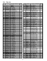
Panasonic CT-27SL14 - 27

Ref.

No.

Part No.

Part Name & Description

Remarks

C806

ECQM4103KZW

CAP P .01UF-K-400V

C808

ECA1HM470B

CAP E 47UF-50V

C809

TACCW471T50V

CAP C 470PF-K-50V

C810

TACCW471T50V

CAP C 470PF-K-50V

C812

ECQU2A224MLA

CAP P .22UF-M-250V

C812

ECQU2A682MLA

CAP P .0068UF-M-250V

C815

ECQU2A224MLA

CAP P .22UF-M-250V

C820

ECA1CM101B

CAP E 100UF-16V

C821

TCJ2VF1H103Z

CAP C .01UF-Z-50V

C822

ECKR3A221KBP

CAP C 220PF-K-1KV

C823

ECA1VM471B

CAP E 470UF-35V

C824

ECKR3A102KBP

CAP C 1000PF-K-1KV

C825

EEUMG2C221SC

CAP E 220UF-160V

C826

ECKR3A471KBP

CAP C 470PF-K-1KV

C827

ECA1CM102B

CAP E 1000UF-16V

C828

ECA160V33UE

CAP E 33UF-160V

C829

ECA1CM471B

CAP E 470UF-16V

C830

ECA1CM471B

CAP E 470UF-16V

C831

ECJ2VF1H103Z

CAP C .01UF-Z-50V
CT-27SL14J CT-27SL14UJ

C901

TCJ2VB1H103K

CAP C .01UF-K-50V

C904

TACCW103T50V

CAP C .010UF-50V

C952

ECA1HM100B

CAP E 10UF-50V

C953

TACCW103T50V

CAP C .010UF-50V

C958

ECA2CM470E

CAP E 47UF-160V

C959

ECKW2H103ZF7

CAP C .01F-Z-500V

C960

ECCR2H151J5

CAP C 150-500V

C961

ECA2AM100B

CAP E 10UF-100V

C962

ECKW2H103ZF7

CAP C .01F-Z-500V

C963

ECCR1H151J5

CAP DISC 150-5-50V

C964

ECA1CHG101B

CAP E 100UF-16V

C966

ECA1CHG101B

CAP E 100UF-16V

C967

ECA1CM221B

CAP E 10UF-16V

C968

TACCW103T50V

CAP C .010UF-50V

C969

TACCW103T50V

CAP C .010UF-50V

C971

ECKR1H222KB5

CAP C 2200PF-K-50V

C2201

ECA1HM4R7B

CAP E 4.7UF-50V

C2202

ECA1HM2R2B

CAP E 2.2UF-50V

C2203

ECA1HM4R7B

CAP E 4.7UF-50V

C2204

AP106K016CAE

CAP T 10UF-16V

C2205

ECA1HMR33B

CAP E .33UF-50V

C2206

ECQB1H223JF3

CAP P .022UF-J-50V

C2207

AP335K016CAE

CAP T 3.3UF-16V

C2208

ECJ2VB1C104K

CAP C .1UF-K-16V

C2209

ECJ2VB1C104K

CAP C .1UF-K-16V

C2210

ECJ2VB1C104K

CAP C .1UF-K-16V

C2212

ECQB1H473JF3

CAP P .047UF-J-50V

C2213

ECA1HMR47B

CAP E .47UF-50V

C2214

ECA1AM101B

CAP E 100UF-10V

C2215

EEANA1E100B

CAP E 10UF-25V

C2216

TCJ2VC1H100D

CAP C 10PF-J-50V

C2217

ECJ2VB1H102K

CAP C .001UF-K-50V

C2218

ECJ2VB1H102K

CAP C .001UF-K-50V

C2219

ECJ2VF1C105Z

CAP C 1.0UF-Z-16V

C2220

ECJ2VF1C105Z

CAP C 1.0UF-Z-16V

C2301

ECA1EM102E

CAP E 1000UF-25V

C2302

ECA1HM010B

CAP E 1UF-50V

C2304

ECA1CM101B

CAP E 100UF-16V

C2307

ECA1CM102B

CAP E 1000UF-16V

C2308

ECJ2VF1H103Z

CAP C .01UF-Z-50V

C2309

ECA1HM010B

CAP E 1UF-50V

C2312

ECA1HM010B

CAP E 1UF-50V

C2313

ECA1EM101B

CAP E 100UF-25V

C2317

ECA1CM102B

CAP E 1000UF-16V

C2319

ECA1HM010B

CAP E 1UF-50V

C2350

ECA1CM101B

CAP E 100UF-16V

C2351

ECA0JM221B

CAP E 220UF-6.3V

C2501

TCJ2VB1H332K

CAP C .0033UF-K-50V

C2502

TCJ2VB1H332K

CAP C .0033UF-K-50V

C2503

TCJ2VB1H333K

CAP C .033UF-K-50V

C2504

TCJ2VB1H333K

CAP C .033UF-K-50V

C2505

EEANA1E4R7B

CAP E 4.7UF-25V

C2506

EEANA1E4R7B

CAP E 4.7UF-25V

Ref.

No.

Part No.

Part Name & Description

Remarks

C2507

TCJ2VB1H472K

CAP C 4700PF-K-50V

C2508

TCJ2VB1H472K

CAP C 4700PF-K-50V

C2509

ECJ2VB1C104K

CAP C .1UF-K-16V

C2510

ECJ2VB1C104K

CAP C .1UF-K-16V

C2511

ECA1HM010B

CAP E 1UF-50V

C2512

ECJ2VB1C104K

CAP C .1UF-K-16V

C2513

ECA1HM4R7B

CAP E 4.7UF-50V

C2514

ECA1HM4R7B

CAP E 4.7UF-50V

C2515

ECJ2VF1C105Z

CAP C 1.0UF-Z-16V

C2516

ECA1HM4R7B

CAP E 4.7UF-50V

C2517

ECA1HM4R7B

CAP E 4.7UF-50V

C2518

ECA1HM4R7B

CAP E 4.7UF-50V

C2519

ECA1CM220B

CAP E 22UF-16V

C2520

TCJ2VF1H103Z

CAP C .01UF-Z-50V

C2531

ECA1HM4R7B

CAP E 4.7UF-50V

C2532

ECA1HM4R7B

CAP E 4.7UF-50V

C3001

ECA1CM220B

CAP E 22UF-16V

C3002

ECA1CM220B

CAP E 22UF-16V

C3011

ECJ2VF1C105Z

CAP C 1.0UF-Z-16V

C3012

ECA1HM010B

CAP E 1UF-50V

C3013

ECA1CM100B

CAP E 10UF-16V

C3014

ECA1CM100B

CAP E 10UF-16V

C3015

ECA1HM010B

CAP E 1UF-50V

C3016

ECA1HM010B

CAP E 1UF-50V

C3017

ECA1HM010B

CAP E 1UF-50V

C3018

ECA1HM010B

CAP E 1UF-50V

C3019

ECJ2VF1C105Z

CAP C 1.0UF-Z-16V

C3020

ECA1HM010B

CAP E 1UF-50V

C3025

ECA1HM100B

CAP E 10UF-50V

C3121

ECA1CM470B

CAP E 47UF-16V

C3122

TCJ2VF1H103Z

CAP C .01UF-Z-50V

C3234

ECA1CM470B

CAP E 47UF-16V

C3240

TCJ2VF1H103Z

CAP C .01UF-Z-50V

C4322

ECA1CM100B

CAP E 10UF-16V

C4323

ECA1CM470B

CAP E 47UF-16V

C4324

TCJ2VF1H103Z

CAP C .01UF-Z-50V

C4325

ECA1CM100B

CAP E 10UF-16V

C4801

TCJ2VC1H101J

CAP C 100PF-J-50V
CT-27SL14J CT-27SL14UJ

C4802

ECA1HM220B

CAP E 22UF-50V
CT-27SL14J CT-27SL14UJ

C4803

ECQV1H334JL3

CAP P .33UF-J-50V
CT-27SL14J CT-27SL14UJ

C4804

TACCW103T50V

CAP C .010UF-50V
CT-27SL14J CT-27SL14UJ

C4805

ECA1CM102B

CAP E 1000UF-16V
CT-27SL14J CT-27SL14UJ

C4806

ECA1CM101B

CAP E 100UF-16V
CT-27SL14J CT-27SL14UJ

C4806

ECA1CM102B

CAP E 1000UF-16V
CT-27SL14J CT-27SL14UJ

DIODES

D001

MAZ30680ML

DIODE ZENER

D002

MA2C165001VT

DIODE

D003

MAZ30510HL

DIODE

D006

MAZ33000HL

DIODE

D007

MAZ30510HL

DIODE

D010

MAZ40510MF

DIODE ZENER

D055

MAZ40330MF

DIODE ZENER

D358

MA2C165001VT

DIODE

D359

MAZ40270LF

DIODE ZENER

D360

B0HAGP000003

DIODE

D360

MA2C165001VT

DIODE

D361

B0HAGP000003

DIODE

D362

B0HAGP000003

DIODE

D376

B0HAJP000015

DIODE

D380

MA2C029WBF

DIODE

D451

B0EAKL000008

DIODE RECTIFIER

D452

MA2C165001VT

DIODE

D505

D1NL40V70

DIODE

D531

MA2C165001VT

DIODE

D551

B0HAMM000072

DIODE FAST RECOVERY

D554

AU02V0

DIODE RECTIFIER

D556

MA2C165001VT

DIODE

47

Summary of Contents for CT-27SL14 - 27" CRT TV

Page 1: ...le 7 7 TV Location of controls 8 8 Location of controls remote 9 8 1 EUR7613ZB0 9 Color Television This simplified service manual is issued to add listed models to the NA10 family service manuals order No MTNC030733A1 CT 27SL13G MTNC030834A1 CT 24SL13G MTNC030623C1 CT 25L8G A complete parts list and schematics are included in this simplified service manual Please file and use this simplified servi...

Page 2: ...ts 19 13 2 C Board main components 19 14 Reference for PDF colors 20 15 Conductor views 21 15 1 A Board printed circuit 1 of 2 22 15 2 A Board printed circuit 2 of 2 23 15 3 C Board printed circuit 24 16 Block diagrams 25 16 1 Video Signal Block Diagram 26 16 2 Audio Signal Block diagram 27 17 Schematics 28 17 1 English schematic notes 29 17 2 Notas de esquemáticos en español 30 17 3 A Board schem...

Page 3: ...roughly test the unit to ensure that is completely safe to operate Do not use a line isolation transformer when testing Leakage current cold check Unplug the A C cord and connect a jumper between the two plug prongs Measure the resistance between the jumpered AC plug and expose metallic parts such as screwheads antenna terminals control shafts etc If the exposed metallic part has a return path to ...

Page 4: ...k the parts list for correct diode number Component removal 1 Use solder wick to remove solder from component end caps or terminal 2 Without pulling up carefully twist the component with tweezers to break the adhesive 3 Do not reuse removed leadless or chip components since they are subject to stress fracture during removal Chip component installation 1 Put a small amount of solder on the board so...

Page 5: ...nected to TPD15 and cathode to TPD14 3 Apply 75VAC to AC input of isolation transformer 4 Turn the receiver on 5 Apply a monoscope pattern 6 Set customer picture and brightness controls to the minimum 7 Set current within 50µA to 100µA by changing the picture and bright controls 8 Slowly increase AC voltage at the input of the isolation transformer and confirm HHS voltage measure 34 5kV 9 Turn pow...

Page 6: ...free solder has a higher melting point than standard solder Typically the melting point is 50 70 F 30 40 C higher Please use a high temperature soldering iron and set it to 700 20 F 370 10 C Pb free solder will tend to splash when heated too high about 1100 F or 600 C If you must use Pb solder please completely remove all of the Pb free solder on the pins or solder area before applying Pb solder I...

Page 7: ...EAR FRONT 3 2 1 AUDIO OUT FAO F VAO V F V COMPONENT INPUT Y Pb Pr 1 S VIDEO INPUT REAR FRONT 1 0 EPJ HPJ MISC HPJ DIMENSIONS WxDxH 695 16x464x538 46mm 27 36x18 26x21 19in 754 3x534 3x601 6mm 29 69x21 03x23 68in WEIGHT Kg Lbs 34 74 95 35 4 78 04 Note Specifications are subject to change without notice or obligation Dimensions and weights are approximate 6 Board description table CT 24SL14J CT 24SL1...

Page 8: ...7 TV Location of controls 8 ...

Page 9: ...8 Location of controls remote 8 1 EUR7613ZB0 Note For additional information about this remote please refer to the owner s manual section remote operation listed on the parts list section 9 ...

Page 10: ...aussing coil DEG plug from the main board 3 Unplug the CRT 2nd anode button from the main board 4 Remove the C Board from the CRT base and unplug the black wires CRT dag ground C11 C21 5 Disconnect the speakers plug from the A Board 6 Lift the main chassis A Board and all mounted boards completely out with the CRT board attached 7 Perform complete removal of chassis as instructed in disassembly fo...

Page 11: ...9 2 Back cover removal Back Cover 9 3 Inside View 11 ...

Page 12: ...0 2 0V Note Connect the lead of the voltmeter to the appropriate ground Use IC801 s heat sink when the HOT ground symbol is used Otherwise use COLD ground tuner shield IC451 s heat sink or FA2 A BOARD TEST POINT VOLTAGE 24 CRT 27 CRT SOUND C823 22 7 1 0V 22 7 1 0V STB12V C827 12 8 1 0 V 12 8 1 0 V 220V TPA14 205 10 V 217 10 V VERTICAL TPD8 27 4 1 5V 27 4 1 5V 9V IC551 pin 3 9 0 0 5V 9 0 0 5V 5V IC...

Page 13: ...ween the modes Red CHK for service and yellow CHK for aging 7 Press POWER on the remote control to display the service adjustment modes menu select adjustment by pressing the volume right left buttons and channel up down buttons on the remote and ACTION to enter the adjustment Exiting the service mode This TV goes out from service mode when it is unplugged or turned OFF To exit the service mode tu...

Page 14: ...ER PINCUSHION B2 BTMG BOTTOM CORNER PINCUSHION A8 TRAP TRAPEZOID 7F PCCHG PINCUSHION HIGH 0F PCCLG PINCUSHION LOW 1D PCCHS PINCUSHION HIGH 00 PCCLS PINCUSHION LOW 00 TOPSL TOP CORNER PINCUSHION SLICE LEVEL 33 BTMSL BOTTOM CORNER PINCUSHION SLICE LEVEL 33 VEAMP VERTICAL SIZE 5D V C VERTICAL LINEARITY 58 V S VERTICAL SIZE CORRECTION 0A VPOS VERTICAL POSITION 7F ID1 ID SWITCH 1 FC ID2 ID SWITCH 2 5F ...

Page 15: ...NT NOTE if a rainbow pattern generator is available perform the following procedure the next section describes the procedure with no rainbow pattern Make sure that sub contrast adjustment was finished prior to perform this adjustment PREPARATION 1 Normalize the picture settings 2 Set the BRIGHTNESS control to minimum 3 Set the COLOR control to the center 4 Set the TINT control to the center 5 Set ...

Page 16: ...____________07 FF B DR_______________________07 FF PROCEDURE 1 Connect the oscilloscope to KG CRT Board 2 In service mode for making electronic adjustment select BRIGH DAC 3 Press RECALL button on the remote control to collapse the raster service SW 4 Connect oscilloscope to KG on C Board and adjust service mode CUT G DAC until 170 2V above DC ground is measured 5 Remove the probe from KG 6 Turn s...

Page 17: ... POS DATA again 4 Apply a monoscope pattern 5 Confirm that center horizontal line is in center mark on CRT 6 Adjust VEAMP register for correct vertical size by making monoscope round circle leaving 4 marks off the CRT edge Vertical centering adjustment 12 5 3 V S Correction adjustment PREPARATION 1 Apply a crosshatch pattern 2 Normalize the picture settings PROCEDURE 1 Enter to service mode 2 Chec...

Page 18: ...urn P L SW and N R SW ON 3 In service mode adjust the MTS Low Level separation adjustment SEPAL data until the amplitude displayed on the scope is minimum 4 Apply the following signal from the RF signal generator Video 100 IRE flat field 30 modulation Audio 3KHz 30 modulation stereo left only 70 5dB 75Ω OPEN P S 10dB NOTE After setting 30 modulation with P L SW and N R SW OFF turn P L SW and N R S...

Page 19: ...13 Identification of main components 13 1 A Board main components A Board main components 13 2 C Board main components C Board main components 19 ...

Page 20: ...14 Reference for PDF colors 20 ...

Page 21: ...15 Conductor views 21 ...

Page 22: ...15 1 A Board printed circuit 1 of 2 1 2 3 4 5 6 7 8 A B C D E F G H I J A BOARD 1 of 2 TNP2AH060 CT 24SL14J UJ CT 27SL14J UJ 22 ...

Page 23: ...15 2 A Board printed circuit 2 of 2 1 2 3 4 5 6 7 8 A B C D E F G H I J A BOARD 2 of 2 TNP2AH060 CT 24SL14J UJ CT 27SL14J UJ 23 ...

Page 24: ...15 3 C Board printed circuit 1 2 3 4 5 6 7 8 A B C D E F G H I J C BOARD TNP2AA157 CT 24SL14J UJ CT 27SL14J UJ 24 ...

Page 25: ...16 Block diagrams 25 ...

Page 26: ...Y OUT TV IN MV IN MU IN MCOMP IN R OUT G OUT B OUT 45 19 42 MPU MSCIN 15 Y C JK3003 S VIDEO CT 24SL14J UJ CT 27SL14J UJ MODELS IC3002 FRONT VIDEO SW 5 7 13 1 7 3 PV1 PV2 PV1 PV2 IN1 IN2 0UT 2 SW 4 6 17 1 2 67 70 C BOARD R G B VM OUT IC351 A14 C1 B OUT G OUT R OUT B IN G IN R IN VM 1 CRT C2 1 2 3 4 5 1 5 4 3 38 9 8 7 3 1 2 VM 41 Q361 Q358 Q355 Q362 Q359 Q356 Q360 Q357 Q354 26 ...

Page 27: ... MPX IN R OUT L OUT AUX L2 R IN L IN R OUT L OUT R L AUX L1 AUX R1 3 7 MTS VOL MUTE IC001 MPU VOL SP ON OFF R L CT 24SL14J UJ CT 27SL14J UJ MODELS R L 12 1 6 Audio Switching IC3101 14 L2 R2 L R L R Mixed R2 L2 3 9 24 23 84 76 8 11 T U N E R JK3004 TO AUDIO AMP VAO L VAO R 4 8 L3 R3 1 11 2 IC2501 21 22 2 5 R IN L IN 1 30 R OUT L OUT 23 8 27 ...

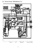
Page 28: ...17 Schematics 28 ...

Page 29: ...17 1 English schematic notes 29 ...

Page 30: ...17 2 Notas de esquemáticos en español 30 ...

Page 31: ...17 3 A Board schematic TNP2AH060DB 1 of 4 1 2 3 4 5 6 7 8 A B C D E F G H I J A BOARD 1 of 4 TNP2AH060DB CT 24SL14J CT 24SL14UJ 31 ...

Page 32: ...17 4 A Board schematic TNP2AH060DB 2 of 4 1 2 3 4 5 6 7 8 A B C D E F G H I J A BOARD 2 of 4 TNP2AH060DB CT 24SL14J CT 24SL14UJ 32 ...

Page 33: ...17 5 A Board schematic TNP2AH060DB 3 of 4 1 2 3 4 5 6 7 8 A B C D E F G H I J A BOARD 3 of 4 TNP2AH060DB CT 24SL14J CT 24SL14UJ 33 ...

Page 34: ...17 6 A Board schematic TNP2AH060DB 4 of 4 1 2 3 4 5 6 7 8 A B C D E F G H I J A BOARD 4 of 4 TNP2AH060DB CT 24SL14J CT 24SL14UJ 34 ...

Page 35: ...17 7 A Board schematic TNP2AH060MA 1 of 4 1 2 3 4 5 6 7 8 A B C D E F G H I J A BOARD 1 of 4 TNP2AH060MA CT 27SL14J CT 27SL14UJ 35 ...

Page 36: ...17 8 A Board schematic TNP2AH060MA 2 of 4 1 2 3 4 5 6 7 8 A B C D E F G H I J A BOARD 2 of 4 TNP2AH060MA CT 27SL14J CT 27SL14UJ 36 ...

Page 37: ...17 9 A Board schematic TNP2AH060MA 3 of 4 1 2 3 4 5 6 7 8 A B C D E F G H I J A BOARD 3 of 4 TNP2AH060MA CT 27SL14J CT 27SL14UJ 37 ...

Page 38: ...17 10 A Board schematic TNP2AH060MA 4 of 4 1 2 3 4 5 6 7 8 A B C D E F G H I J A BOARD 4 of 4 TNP2AH060MA CT 27SL14J CT 27SL14UJ 38 ...

Page 39: ...17 11 C Board schematic TNP2AA157AN AR 1 of 2 1 2 3 4 5 6 7 8 A B C D E F G H I J C BOARD 1 of 2 TNP2AA157AN AR CT 24SL14J UJ CT 27SL14J UJ 39 ...

Page 40: ...17 12 C Board schematic TNP2AA157AN AR 2 of 2 1 2 3 4 5 6 7 8 A B C D E F G H I J C BOARD 2 of 2 TNP2AA157AN AR CT 24SL14J UJ CT 27SL14J UJ 40 ...

Page 41: ...0 2 20 2 20 2 20 IC002 1 2 3 4 5 6 7 8 0 00 0 00 0 00 0 00 3 40 3 40 5 20 5 20 IC003 1 2 3 0 00 3 31 3 27 IC004 1 2 3 4 5 0 00 0 00 0 00 3 30 3 30 IC005 1 2 3 4 9 10 3 30 0 00 9 10 IC2301 1 2 3 4 5 6 7 8 9 10 11 12 7 50 5 60 21 00 0 00 5 60 7 50 10 60 1 30 0 00 22 70 3 20 10 20 IC3001 1 2 3 4 5 6 7 8 4 10 0 20 4 10 0 00 4 10 9 00 4 30 0 00 IC451 1 2 3 4 5 6 7 2 00 27 80 1 20 0 00 17 60 27 90 2 00 ...

Page 42: ... 00 13 00 0 00 B C E B C E Q355 4 30 8 40 3 60 Q3002 1 30 3 30 0 70 Q354 4 50 8 50 3 80 Q3001 1 30 3 30 0 70 Q356 4 40 8 40 3 70 Q357 2 60 4 50 2 00 Q2361 0 30 0 00 0 00 Q2362 0 00 0 10 0 00 Q2363 1 34 0 00 1 50 Q3193 0 60 0 03 0 00 Q3194 0 05 7 80 0 00 Q751 7 50 8 90 0 00 G D S B C E Q757 0 00 7 60 0 00 Q901 1 00 5 20 0 40 Q902 5 20 2 40 5 80 C BOARD TNP2AA157 Q952 1 50 5 70 1 50 Q953 6 30 8 90 5...

Page 43: ...IC001 PIN 50 OSC 6 780mVp p IC451 PIN 1 VERT IN 7 2 20 Vp p Q411 B V DRIVE 8 57 8 Vp p IC451 PIN 5 V OUT 9 A Board 26 8 Vp p A12 PIN 2 HEATER 12 508 KVp p Q551 Collector H OUT 13 408 Vp p IC801 PIN 1 14 2 76 Vp p IC801 PIN 7 15 110 Vp p Q501 Collector 16 30 4 Vp p IC451 PIN 3 PUMP UP 10 3 8 Vp p IC501 PIN 4 H DRIVE 11 10MHz X tal CT 24SL14J UJ CT 27SL14J UJ 43 ...

Page 44: ...18 Parts location 44 ...

Page 45: ...19 Parts list 19 1 Parts list notes 45 ...

Page 46: ... 068UF J 50V C451 ECA1HM010B CAP E 1UF 50V C452 ECA1CM220B CAP E 22UF 16V Ref No Part No Part Name Description Remarks C454 ECA1VHG101B CAP E 100UF 35V C455 ECA1EM102E CAP E 1000UF 25V C458 ECA1HM010B CAP E 1UF 50V C459 ECA1VHG471B CAP E 470UF 35V C460 ECQB1224KF3 CAP P 22UF K 100V C461 ECQB1104JF3 CAP P 10UF J 100V C462 TCJ2VF1H103Z CAP C 01UF Z 50V CT 27SL14J CT 27SL14UJ C462 TCJ2VF1H683Z CAP C ...

Page 47: ...JM221B CAP E 220UF 6 3V C2501 TCJ2VB1H332K CAP C 0033UF K 50V C2502 TCJ2VB1H332K CAP C 0033UF K 50V C2503 TCJ2VB1H333K CAP C 033UF K 50V C2504 TCJ2VB1H333K CAP C 033UF K 50V C2505 EEANA1E4R7B CAP E 4 7UF 25V C2506 EEANA1E4R7B CAP E 4 7UF 25V Ref No Part No Part Name Description Remarks C2507 TCJ2VB1H472K CAP C 4700PF K 50V C2508 TCJ2VB1H472K CAP C 4700PF K 50V C2509 ECJ2VB1C104K CAP C 1UF K 16V C2...

Page 48: ...TCH IC4801 AN15530B TILT CORRECTION OP AMP CT 27SL14J CT 27SL14UJ COILS Ref No Part No Part Name Description Remarks L002 EXCELSA39V EMI BEAD CORE L005 EXCELSA35T FERRITE BEAD L006 EXCELSA35T FERRITE BEAD L007 ELESN330JA COIL 33UH CT 27SL14J CT 27SL14UJ L008 G0C470KA0029 COIL PEAKING 47UH L010 G0C2R2KA0029 COIL PEAKING 2 2UH L011 EXCELSA26T FERRITE BEAD L012 G0C2R2KA0029 COIL PEAKING 2 2UH L013 EX...

Page 49: ...R047 ERJ6GEYJ472V RES M 4 7K J 1 10W R048 ERJ6GEYJ101V RES M 100 J 1 10W R050 ERJ6GEYJ102V RES M 1K J 1 10W R052 ERJ6GEYJ103V RES M 10K J 1 10W R053 ERJ6GEYJ101V RES M 100 J 1 10W R055 ERJ6GEYJ103V RES M 10K J 1 10W R056 ERJ6GEYJ471V RES M 470 J 1 10W R057 ERJ6GEYJ101V RES M 100 J 1 10W R059 ERJ6GEYJ121V RES M 120 J 1 10W R060 ERJ6GEYJ101V RES M 100 J 1 10W R061 ERJ6GEYJ221V RES M 220 J 1 10W R062...

Page 50: ...T 27SL14UJ R557 ERDS2TJ223T RES C 22K J 1 4W R558 ERDS2TJ223T RES C 22K J 1 4W Ref No Part No Part Name Description Remarks R559 ERG2FJ683H RES M 68K J 2W R561 ERG2FJ102H RES M 1K J 2W R562 ERG2FJ270H RES M 27 J 2W R563 ERG3FJ150H RES M 15 J 3W R564 ERDS2TJ563T RES C 56K J 1 4W R565 ERDS2TJ683T RES C 68K J 1 4W R592 ERJ6GEYJ472V RES M 4 7K J 1 10W R605 ERDS2TJ103T RES C 10K J 1 4W R606 ERJ6GEYJ562...

Page 51: ...F 1 10W R3029 ERJ6GEYJ101V RES M 100 J 1 10W R3030 ERJ6GEYJ223V RES M 22K J 1 10W R3031 ERJ6GEYJ223V RES M 22K J 1 10W R3032 ERJ6GEYJ223V RES M 22K J 1 10W R3033 ERJ6GEYJ223V RES M 22K J 1 10W R3034 ERJ6GEYJ471V RES M 470 J 1 10W R3035 ERJ6GEYJ562V RES M 5 6K J 1 10W R3036 ERJ6GEYJ183V RES M 18K J 1 10W R3037 ERJ6GEYJ471V RES M 470 J 1 10W R3038 ERJ6GEYJ562V RES M 5 6K J 1 10W Ref No Part No Part ...

Page 52: ...TXFKU02JSER BACK CABINET CT 24SL14J CT 24SL14UJ JK3001 TJB2AA0221 A V 8 PIN TERMINAL JK3002 TJB2AA0045 FRONT A V TERMINAL JK3003 TJB2AA0421 S VIDEO TERMINAL JK3004 TJB2AA0211 1 AUDIO OUT 2 PIN TERMINAL OTHER ACCESSORIES M008 TQB2AA0499 OWNER S MANUAL M009 EUR7613ZB0 REMOTE CONTROL M010 UR76EC0303E BATTERY COVER EUR7613ZB0 M011 EUR7613Z6A REMOTE CONTROL M012 UR76EC0303D BATTERY COVER EUR7613Z6A 52 ...

Reviews: