


12.6. MTS circuit adjustments
The MTS circuit adjustments require two steps:
1. Input level adjustment.
2. Stereo separation adjustment.
Input level adjustment
Service DAC adjustment (MTSIN)
PREPARATION
1. Connect an RMS meter with filter jig as shown in
figure to TPE11.
Filter Jig
2. Connect an RF signal generator to the RF antenna
input.
PROCEDURE
1. Apply the following signal from the RF signal
generator:
•
•
•
•
Video: 100 IRE flat field, 30% modulation.
•
•
•
•
Audio: 300Hz, 100% modulation, monaural (70
±5dB, 75
Ω
OPEN, P/S 10dB). Make sure that
the 75µs pre-emphasis is OFF.
2. Adjust the MTS input level adjustment “MTSIN” data
until the RMS voltage measured is 120 ± 4.0mVrms.
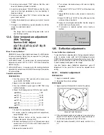
Stereo separation adjustment (SEPAH)
PREPARATION
1. Connect an R.F. signal generator to the RF antenna
input.
2. Connect a scope to TPE10.
PROCEDURE
1. Select stereo mode in audio menu
2. Apply the following signal from the RF signal
generator:
•
•
•
•
Video: 100 IRE flat field, 30% modulation.
•
•
•
•
Audio: 300Hz, 30% modulation, stereo (left only)
(70±5dB, 75
Ω
OPEN, P/S 10dB).
NOTE
After setting 30% modulation with P.L. SW
and N.R. SW OFF, turn P.L. SW and N.R.
SW ON.
3. In service mode, adjust the MTS Low-Level
separation adjustment “SEPAL” data until the
amplitude displayed on the scope is minimum.
4. Apply the following signal from the RF signal
generator:
•
•
•
•
Video: 100 IRE flat field, 30% modulation
•
•
•
•
Audio: 3KHz, 30% modulation, stereo (left only)
(70 ±5dB, 75
Ω
OPEN, P/S 10dB).
NOTE
After setting 30% modulation with P.L. SW
and N.R. SW OFF, turn P.L. SW and N.R.
SW ON.
5. Adjust the MTS High-level separation adjustment
“SEPAH” until the amplitude displayed on the scope
is minimum.
6. Repeat above steps 2 through 5 until the amplitude
is at minimum for both signals.
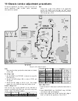
12.7. Clock adjustment (CLOCK)
PREPARATION
Connect the frequency counter from TP017
(IC001 pin 79) to cold ground
PROCEDURE
1. Turn the receiver “OFF” with the A.C. power applied.
2. Measure TP017 (IC001 pin 79) for the frequency of the
waveform and record the reading.
NOTE
3. TP017 (IC001 pin 79) measurement must have at least
four digits of resolution following the decimal point.
Example: 000.0000
4. Place the receiver into service mode for making
electronic adjustment, select the clock adjustment DAC
“CLOCK”.
5. Calculate and set “CLOCK” based on the following
formula:
NOTE
TP017 (IC001 pin 79) measurement will not change
regardless of the value stored in CLOCK.
18
Summary of Contents for CT-27SL14 - 27" CRT TV
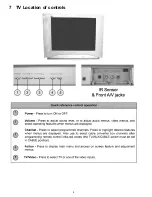
Page 8: ...7 TV Location of controls 8 ...
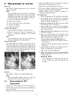
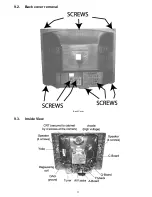
Page 11: ...9 2 Back cover removal Back Cover 9 3 Inside View 11 ...
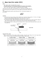
Page 20: ...14 Reference for PDF colors 20 ...
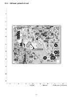
Page 21: ...15 Conductor views 21 ...
Page 25: ...16 Block diagrams 25 ...
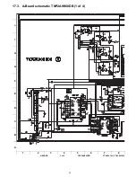
Page 28: ...17 Schematics 28 ...
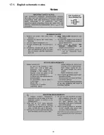
Page 29: ...17 1 English schematic notes 29 ...
Page 30: ...17 2 Notas de esquemáticos en español 30 ...
Page 44: ...18 Parts location 44 ...


