Panasonic CS-TZ20WKEW Service Manual Download Page 87

87 

13.7  Repairing of refrigerant cycle / Brazing point 

13.7.1  Preparation for repairing of refrigerant cycle / brazing 

Brazing which is a technique needed for repairing refrigerant cycle requires advanced technique and experience, and 
this brazing procedure can only be performed by the workers who completed “Gas Welding Skill Training” regulated 
by the Occupational Safety and Health Act, and went through the training programs of refrigerant operations. 
Dismantling and re-connecting (assembling) refrigerant system requires working space, and the space has to ensure 
good air flow and fire prevention (water bucket and fire extinguisher). Moreover, the worker has to ensure the 
wearing of goggles, grabs, safety shoes, and long sleeve shirts, and be aware of work safety and attempt to prevent 
secondary defect (quality assurance of products). For brazing the indoor / outdoor unit structural components (heat 
exchangers, compressors, expansion valves, four-way valve blocks), after the recovery of all refrigerant, confirm that 
no refrigerant remains in the system, and fully open the 2-way and 3-way valves. When the brazing is conducted 
outside, check and make sure no refrigerant is contained in the air (be careful with vaporized refrigerant). 
Furthermore, protect the compressor terminal with metal plates, and heat but use wet clothes to cool down (releasing 
the heat) the expansion valves, and four way valves (prevent destruction of parts). In brazing, it is important to pour 
the brazing material without melting the base metal based on capillary action principle. In case of holes and oxidizing 
caused by overheating, do not perform re-brazing or alteration but replace the parts. 

13.7.2 Adjustment 

of vacuum pump pressure 

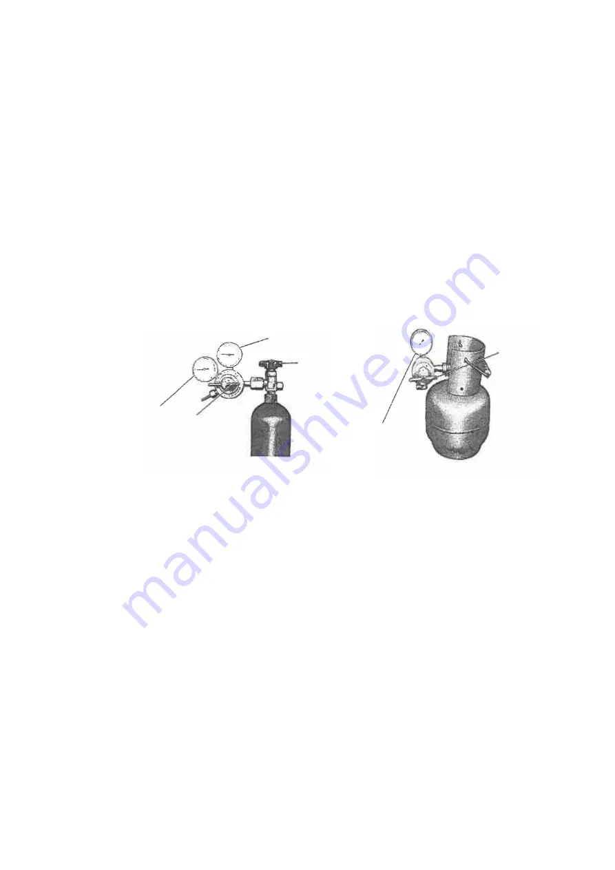
1.  Cylinder with adjustment handle 

1.  Check and confirm the adjustment handle of the 1

st

 pressure adjuster is loosen (anticlockwise). If cylinder 

valve is opened when the 1

st

 gauge pressure adjust handle is closed, the 2

nd

 gauge might get broken. 


2.  Open the cylinder valve, and check the remaining amount with the first t side pressure gauge. 
3.  Check the pressure of 2

nd

 gauge and turn the adjustment handle to clock-wise direction to adjust the 

pressure. 

 Oxygen 2

nd

 side gauge pressure

・・・・・・・・・・

0.5 MPa (5.0 k

g

f / cm

2

 Propane 2

nd

 side gauge pressure

・・・・・・・

0.05 MPa (0.5 k

g

f / cm

2


The primary gauge

(High pressure)

The secondary gauge

(Low pressure)

The secondary gauge

(Low pressure)

Adjustment

handle

Adjustment

handle

Oxygen regulator

Propane regulator

Main valve

Main valve

Summary of Contents for CS-TZ20WKEW

Page 1: ...be serviced or repaired only by experienced professional technicians Any attempt to service or repair the products dealt with in this service information by anyone else could result in serious injury...

Page 2: ...ration demonstrates the correct electrical works for both type A Single Connection B Multiple Connection 3 2 S1 Colour of wires connection cable Terminals on the indoor unit Terminals on the outdoor u...

Page 3: ...no error code no cooling no warming 93 14 Operation Control 95 14 1 Basic Function 95 14 2 Indoor Fan Motor Operation 96 14 3 Outdoor Fan Motor Operation 97 14 4 Airflow Direction 98 14 5 Timer Contr...

Page 4: ...ormance Data Sensible Capacity 181 20 2 Heat Mode Performance Data 184 21 Service Data 186 21 1 Cool Mode Outdoor Air Temperature Characteristic 186 21 2 Heat Mode Outdoor Air Temperature Characterist...

Page 5: ...instructions Please remind the customer to keep the operating instructions for future reference WARNING 1 Do not use means to accelerate the defrosting process or to clean other than those recommended...

Page 6: ...Current Device RCD with sensitivity of 30mA at 0 1 sec or less Otherwise it may cause electrical shock and fire in case of equipment breakdown or insulation breakdown 20 During installation install t...

Page 7: ...r the permanent connection Use an approved 16A 3 4 2 25HP 20A 2 5HP circuit breaker for the permanent connection It must be a double pole switch with a minimum 3 0 mm contact gap 9 Installation or ser...

Page 8: ...arly check the alarms mechanical ventilation and detectors at least once a year where as required by national regulations to ensure their correct functioning 8 A logbook shall be maintained The result...

Page 9: ...rant detector prior to and during work to ensure the technician is aware of potentially flammable atmospheres Ensure that the leak detection equipment being used is suitable for use with flammable ref...

Page 10: ...erse environmental effects The check shall also take into account the effects of aging or continual vibration from sources such as compressors or fans 6 Detection of flammable refrigerants Under no ci...

Page 11: ...ure that the cylinders and the equipment are removed from site promptly and all isolation valves on the equipment are closed off k Recovered refrigerant shall not be charged into another refrigeration...

Page 12: ...L QLo dB A 37 25 20 40 26 20 Power Level dB 53 56 Outdoor Noise H L dB A 46 47 Power Level dB 61 62 Heating Capacity kW 0 70 2 70 3 60 0 80 3 30 4 10 BTU h 2390 9210 12300 2730 11300 14000 kcal h 600...

Page 13: ...97 175 5 30 187 Heat m 3 min ft 3 min 5 99 211 5 94 209 Lo Cool m 3 min ft 3 min 6 44 227 6 68 235 Heat m 3 min ft 3 min 7 01 247 7 10 250 Me Cool m 3 min ft 3 min 8 48 299 8 80 310 Heat m 3 min ft 3...

Page 14: ...ontol Electronic Contol Protection Device Electronic Contol Electronic Contol Dry Bulb Wet Bulb Dry Bulb Wet Bulb Indoor Operation Range Cooling Maximum C 32 23 32 23 Minimum C 16 11 16 11 Heating Max...

Page 15: ...A 42 30 20 44 31 29 Power Level dB 58 60 Outdoor Noise H L dB A 48 49 Power Level dB 63 64 Heating Capacity kW 0 80 4 00 5 10 0 80 5 00 6 80 BTU h 2730 13600 17400 2730 17100 23200 kcal h 690 3440 439...

Page 16: ...73 202 7 74 273 Heat m 3 min ft 3 min 5 94 209 7 53 265 Lo Cool m 3 min ft 3 min 7 95 280 8 27 292 Heat m 3 min ft 3 min 9 22 325 9 65 340 Me Cool m 3 min ft 3 min 9 86 348 10 39 366 Heat m 3 min ft...

Page 17: ...ntol Electronic Contol Protection Device Electronic Contol Electronic Contol Dry Bulb Wet Bulb Dry Bulb Wet Bulb Indoor Operation Range Cooling Maximum C 32 23 32 23 Minimum C 16 11 16 11 Heating Maxi...

Page 18: ...44 37 33 45 37 34 Power Level dB 60 60 Outdoor Noise H L dB A 48 49 Power Level dB 63 64 Heating Capacity kW 0 98 5 80 7 50 0 98 7 00 8 20 BTU h 3340 19800 25600 3340 23900 28000 kcal h 840 4990 6450...

Page 19: ...310 13 01 459 Heat m 3 min ft 3 min 9 22 324 14 01 494 Lo Cool m 3 min ft 3 min 9 97 352 14 62 516 Heat m 3 min ft 3 min 10 50 370 16 02 565 Me Cool m 3 min ft 3 min 11 24 396 17 83 629 Heat m 3 min f...

Page 20: ...onic Contol Electronic Contol Protection Device Electronic Contol Electronic Contol Dry Bulb Wet Bulb Dry Bulb Wet Bulb Indoor Operation Range Cooling Maximum C 32 23 32 23 Minimum C 16 11 16 11 Heati...

Page 21: ...H L QLo dB A 47 38 35 Power Level dB 63 Outdoor Noise H L dB A 52 Power Level dB 66 Heating Capacity kW 0 98 8 60 9 90 BTU h 3340 29300 33800 kcal h 840 7400 8510 Running Current A 10 90 Input Power...

Page 22: ...ool m 3 min ft 3 min 13 41 473 Heat m 3 min ft 3 min 14 42 509 Lo Cool m 3 min ft 3 min 15 02 530 Heat m 3 min ft 3 min 16 43 580 Me Cool m 3 min ft 3 min 18 64 658 Heat m 3 min ft 3 min 19 64 693 Hi...

Page 23: ...tion Range Cooling Maximum C 32 23 Minimum C 16 11 Heating Maximum C 30 Minimum C 16 Outdoor Operation Range Cooling Maximum C 43 26 Minimum C 10 Heating Maximum C 24 18 Minimum C 15 16 1 Cooling capa...

Page 24: ...A 37 25 20 40 26 20 Power Level dB 53 56 Outdoor Noise H L dB A 46 47 Power Level dB 61 62 Heating Capacity kW 0 70 2 70 3 60 0 80 3 30 4 10 BTU h 2390 9210 12300 2730 11300 14000 kcal h 600 2320 3100...

Page 25: ...97 175 5 30 187 Heat m 3 min ft 3 min 5 99 211 5 94 209 Lo Cool m 3 min ft 3 min 6 44 227 6 68 235 Heat m 3 min ft 3 min 7 01 247 7 10 250 Me Cool m 3 min ft 3 min 8 48 299 8 80 310 Heat m 3 min ft 3...

Page 26: ...ontol Electronic Contol Protection Device Electronic Contol Electronic Contol Dry Bulb Wet Bulb Dry Bulb Wet Bulb Indoor Operation Range Cooling Maximum C 32 23 32 23 Minimum C 16 11 16 11 Heating Max...

Page 27: ...A 42 30 20 44 37 33 Power Level dB 58 60 Outdoor Noise H L dB A 48 48 Power Level dB 63 63 Heating Capacity kW 0 80 4 00 5 10 0 98 5 80 7 50 BTU h 2730 13600 17400 3340 19800 25600 kcal h 690 3440 439...

Page 28: ...73 202 8 80 310 Heat m 3 min ft 3 min 5 94 209 9 22 324 Lo Cool m 3 min ft 3 min 7 95 280 9 97 352 Heat m 3 min ft 3 min 9 22 325 10 50 370 Me Cool m 3 min ft 3 min 9 86 348 11 24 396 Heat m 3 min ft...

Page 29: ...Contol Electronic Contol Protection Device Electronic Contol Electronic Contol Dry Bulb Wet Bulb Dry Bulb Wet Bulb Indoor Operation Range Cooling Maximum C 32 23 32 23 Minimum C 16 11 16 11 Heating Ma...

Page 30: ...aximum chargeless length m 20 20 20 30 30 Additional gas amount over chargeless length g m 15 15 15 20 20 Note Available Remarks for CU 2Z35TBE CU 2Z41TBE CU 2Z50TBE 1 At least two indoor units must b...

Page 31: ...kW to 11 5kW From 4 5kW to 14 7kW From 4 5kW to 18 3kW Pipe length 1 room maximum pipe length m 25 25 25 Allowable elevation m 15 15 15 Total allowable pipe length m 60 70 80 Total pipe length for max...

Page 32: ...W to 7 7kW From 4 5kW to 9 5kW Pipe length 1 room maximum pipe length m 20 20 25 Allowable elevation m 10 10 15 Total allowable pipe length m 30 30 50 Total pipe length for maximum chargeless length m...

Page 33: ...on only Easy to use remote control Quality Improvement o Random auto restart after power failure for safety restart operation o Gas leakage protection o Prevent compressor reverse cycle o Inner protec...

Page 34: ...ifying Filter Air Filters Front Panel Horizontal Airflow direction louver Manually adjustable Vertical Airflow direction louver Do not adjust by hand Remote Control receiver INDICATOR White White Whit...

Page 35: ...n speed selection Quiet operation Airflow direction adjustment Check Sleep operation Timer setting Temperature setting Remote control display Operation mode Powerful operation OFF ON FAN SPEED QUIET T...

Page 36: ...der Remote Control 165 close 217 Open 59 69 64 Right piping hole Left piping hole 497 4 120 115 216 168 115 60 Installation plate Indoor unit external dimensions line PIPE HOLE CENTER 115mm TO HOLE CE...

Page 37: ...ide View Unit mm Left piping hole Right piping hole Indoor unit external dimensions line Installation plate 13 264 128 256 741 4 0 5 5 0 5 5 256 128 128 270 320 Remote Control Holder Remote Control 16...

Page 38: ...on Anchor Bolt Pitch 320 x 570 Side View Side View Front View Top View Unit mm 2 way valve at Liquid side High Pressure 3 way valve at Gas side Low Pressure 1000 mm 100 mm 100 mm Top View Front View S...

Page 39: ...7 34 7 131 613 131 2 7 5 7 8 360 5 82 35 Top View Front View Side View Side View Anchor Bolt Pitch 360 5 613 Space necessary for installation 100mm 100mm 1000mm Unit mm 3 way valve at Gas side Low Pr...

Page 40: ...5WKEW CU RZ35WKE INDOOR OUTDOOR INTAKE AIR TEMP SENSOR AIR TEMP SENSOR PIPE TEMP SENSOR 1 PIPE TEMP SENSOR 2 TANK SENSOR PIPE TEMP SENSOR LIQUID SIDE 2 WAY VALVE 3 WAY VALVE GAS SIDE COOLING HEAT EXCH...

Page 41: ...DOOR INTAKE AIR TEMP SENSOR PIPE TEMP SENSOR AIR TEMP SENSOR LIQUID SIDE 2 WAY VALVE 3 WAY VALVE GAS SIDE COOLING HEAT EXCHANGER EVAPORATOR HEATING COMPRESSOR CONDENSER PROCESS TUBE STRAINER EXPANSION...

Page 42: ...IPE TEMP SENSOR AIR TEMP SENSOR LIQUID SIDE 2 WAY VALVE 3 WAY VALVE GAS SIDE COOLING HEAT EXCHANGER EVAPORATOR HEATING COMPRESSOR CONDENSER PROCESS TUBE STRAINER EXPANSION VALVE 4 WAYS VALVE ACCUMULAT...

Page 43: ...43 8 Block Diagram 8 1 Indoor Unit FUSE 301 RY PWR2 RY PWR TEMP FUSE SINGLE PHASE POWER SUPPLY SC U 2 3 M TEMP FUSE FOR TZ60 71WK ONLY INDOOR UNIT L1 S1 N...

Page 44: ...1 CU TZ20WKE CU TZ25WKE CU TZ35WKE CU TZ42WKE CU RZ20WKE CU RZ25WKE CU RZ35WKE RY PWR RY AC PTC PTC1 FUSE102 FUSE103 FUSE105 4 WAYS VALVE SC NTC TH1 NOISE FILTER FUSE101 IC19 FUSE104 MS 3 REAC TOR MS...

Page 45: ...2 CU TZ50WKE CU TZ60WKE CU TZ71WKE CU RZ50WKE 3 2 S1 IC19 Q1 FAN MOTOR COMPRESSOR FUSE1 FUSE6 FUSE3 FUSE5 FUSE8 REACTOR 4 WAY VALVE SC NTC TH1 SEN1 RY PWR RY AC PTC2 PTC MS 3 MS 3 OUTDOOR UNIT NOISE...

Page 46: ...SPLAY AND RECEIVER CN DISP WHT 1 6 REMOTE CONTROLLER COMPLETE FAN MOTOR CN TH RED PIPING TEMP SENSOR 1 THERMISTOR PIPING TEMP SENSOR 2 THERMISTOR SUCTION TEMP SENSOR THERMISTOR AC308 BLK RY PWR RY PWR...

Page 47: ...R MAIN RECTIFICATION CIRCUIT B W BL R COMMUNICATION CIRCUIT NOISE FILTER CIRCUIT FUSE301 T3 15A L250V CN 102 WHT 1 1 3 3 CN 103 WHT ELECTRONIC CONTROLLER SUB 1 5 GR GR GR GR 1 8 3 ELECTRONIC CONTROLLE...

Page 48: ...OLLER GRY RAT2 GRY RAT1 GRY GRY TERMINAL BOARD OUTDOOR AIR TEMP SENSOR THERMISTOR 1 4 CN TH WHT PIPING TEMP SENSOR THERMISTOR 1 3 CN TANK WHT COMP TEMPERATURE SENSOR THERMISTOR YLW YLW 1 3 CN HOT WHT...

Page 49: ...GRY RAT1 GRY CN TH1 WHT CN TANK WHT CN STM1 WHT CN HOT WHT GRY REACTOR RAT2 GRY FUSE 5 20A 250V COMMUNICATION CIRCUIT RECTIFICATION CIRCUIT FUSE 6 20A 250V FUSE 8 T3 15A L250V NOISE FILTER CIRCUIT 3 D...

Page 50: ...CONTROLLER WIFI MODULE CN WLAN BLK CN WLAN WHT 4 1 3 8 1 RECTIFICATION CIRCUIT SW01 CN DISP YLW M B BL Y W R t t t 1 6 1 6 5V R62 15k 1 R61 20k 1 R63 C25 1u 16V B3 C27 1u 16V B3 C28 R47 43 1 2W 43 1...

Page 51: ...STM1 WHT 5 1 1 M 5 P BR LEFT RIGHT LOUVER MOTOR R O Y CN STM2 YLW 5 1 1 M 5 P BR R O Y CN STM3 BLU CN TH RED 5 6 t t t 1 1 1 5 FAN MOTOR M CN WLAN WHT 5V C28 R63 C27 1u 16V B3 R61 20k 1 C25 1u 16V B3...

Page 52: ...HT FAN MOTOR NOISE FILTER CIRCUIT 3 5 1 1 10 14 16 3 IC19 ELECTRONIC CONTROLLER FUSE102 T3 15A L250V FUSE103 T3 15A L250V FUSE104 T3 15A L250V FUSE105 15A 250V PFC CIRCUIT RECTIFICATION CIRCUIT SWITCH...

Page 53: ...CIRCUIT 3 DATA RED AC BLK BLK AC WHT WHT FG1 GRN CN MTR2 WHT PFC CIRCUIT RECTIFCATION CIRCUIT SWITCHING POWER SUPPLY CIRCUIT FUSE 3 T3 15A L250V CN MTR1 RED FAN MOTOR 1 5 3 1 3 1 1 1 4 PIPING TEMP SEN...

Page 54: ...Printed Circuit Board 11 1 1 1 CS TZ20WKEW CS TZ25WKEW CS TZ35WKEW CS TZ42WKEW CS TZ50WKEW CS RZ20WKEW CS RZ25WKEW CS RZ35WKEW CS RZ50WKEW G301 AC303 AC307 AC308 AC304 CN STM1 CN WLAN CN RMT CN TH CN...

Page 55: ...55 11 1 1 2 CS TZ60WKEW CS TZ71WKEW AC303 CN STM1 CN STM3 CN RCV CN DISP CN RMT CN TH JP1 Random Auto Restart enable disable CN DATA3 CN CNT CN FM CN STM2 G301 AC306 CN DATA2 AC304...

Page 56: ...WKEW CS TZ42WKEW CS TZ50WKEW CS RZ20WKEW CS RZ25WKEW CS RZ35WKEW CS RZ50WKEW 11 1 2 2 CS TZ60WKEW CS TZ71WKEW 11 1 3 Sub Printed Circuit Board 11 1 3 1 CS TZ60WKEW CS TZ71WKEW CN DISP LED201 LED202 LE...

Page 57: ...57 11 1 4 WIFI Module Printed Circuit Board...

Page 58: ...58 11 2 Outdoor Unit 11 2 1 CU TZ20WKE CU TZ25WKE CU TZ35WKE CU TZ42WKE CU RZ20WKE CU RZ25WKE CU RZ35WKE CN HOT CN STM CN TH CN MTR1 CN MTR2 CN TANK AC BLK DATA AC WHT POWER TRANSISTOR IPM...

Page 59: ...59 11 2 2 CU TZ50WKE CU TZ60WKE CU RZ50WKE CN HOT CN MTR1 CN MTR2 CN TH1 CN STM1 CN TANK AC BLK DATA AC WHT POWER TRANSISTOR IPM CURRENT TRANSFORMER CT...

Page 60: ...60 11 2 3 CU TZ71WKE CN STM1 CN MTR1 CN MTR2 CN TANK CN TH1 CN HOT AC BLK DATA AC WHT POWER TRANSISTOR IPM CURRENT TRANSFORMER CT...

Page 61: ...in kg LFL Lower flammability limit 0 307 kg m3 h0 Installation height of the appliance 1 8 m for wall mounted SF Safety factor with a value of 0 75 The required minimum room area Amin shall also be go...

Page 62: ...gerant g m Piping Length for add gas m Max Refrigerant Charge kg Indoor Amin m2 Gas Liquid TZ20 RZ20 3 4HP 9 52 mm 3 8 6 35 mm 1 4 5 15 3 15 10 7 5 0 62 Not applicable TZ25 RZ25 1 0HP 15 3 15 10 7 5 0...

Page 63: ...Drill the piping plate hole with 70 mm hole core drill o The meeting point of the extended line is the center of the hole Another method is by putting measuring tape at position as shown in the diagr...

Page 64: ...5 mm from the wall CAUTION When the wall is hollow please be sure to use the sleeve for tube assembly to prevent dangers caused by mice biting the connection cable 4 Finish by sealing the sleeve with...

Page 65: ...ation of piping connection column as mentioned in indoor outdoor unit installation Install the Indoor Unit Secure the Indoor Unit Insulate and finish the piping Step 5 Step 6 Step 7 Step 8 Cover for t...

Page 66: ...and outdoor unit shall be approved polychloroprene sheathed 4 x 1 5 mm2 3 4 1 75HP or 4 x 2 5 mm2 2 0 2 5HP flexible cord type designation 60245 IEC 57 or heavier cord 6 Bind all the indoor and outdoo...

Page 67: ...ard Panel Panel Flip the panel down until click sound before connect indoor and outdoor connection cable Holder Holder Holder Holder Flip the panel down Earth Wire longer than others AC wires for safe...

Page 68: ...nnecting to units to avoid leaking Seal sufficiently the flare nut both gas and liquid sides with neutral cure Alkoxy type ammonia free silicone sealant and insulation material to avoid the gas leak c...

Page 69: ...And then remove the 4 mounting screws 4 Pull the lower section of the front grille towards you to remove the front grille 12 2 8 Check the Drainage Open front panel and remove air filters Drainage che...

Page 70: ...he intake temperature and the discharge is more than 8 C during Cooling operation or more than 14 C during Heating operation 12 2 10 Installation of Dust Collector Filter Air Purifying Filter 1 Open t...

Page 71: ...rting flare nut locate at joint portion of tube assembly onto the copper pipe In case of using long piping Connect the piping Align the center of piping and sufficiently tighten the flare nut with fin...

Page 72: ...essure reading on the gauges Check if there is any pressure drop Waiting time depends on the size of the system 8 If there is any pressure drop perform step 9 12 If there is no pressure drop perform s...

Page 73: ...7 In case of Reusing Existing Refrigerant Piping Observe the followings to decide reusing the existing refrigerant piping Poor refrigerant piping could result in product failure In the circumstances l...

Page 74: ...utes close 3 way valve 3 Take out air conditioner unit 4 Install New Refrigerant air conditioner Most Important Process Purpose To make the oil refrigerant mix together They are in separated condition...

Page 75: ...n 2010 the regulations of American Society of Heating Refrigerating and Air Conditioning Engineers in the United States ANSI ASHRAE34 was issued adopting the grades for refrigerants which are difficul...

Page 76: ...of R410A it is necessary to do installation and service using high pressure tools and components Table 2 Saturated vapor pressure comparison table Unit MPa Temperature Refrigerant R32 R410A R22 20 0...

Page 77: ...tools such as screw drivers metal saws electric drills long nose pliers hole core drills 70 or 65 linen tape levels temperature gauges clamp meters electric knives nippers pipe cutters reamers or scra...

Page 78: ...sizes R32 common R410A R22 Port sizes 1 2 UNF20 7 16 UNF20 5 Charging hoses The pressure resistance of charge hoses is increased At the same time the material is changed to HFC resistant and the size...

Page 79: ...me time the digital scale for refrigerant charging is strengthened by receiving the weight of the refrigerant cylinders with four pillars at the corners The connection ports of charging hoses have two...

Page 80: ...r each HCF type can be used Knowledge for the common usage of tools for R410A R32 R410A and R32 machines use different compressor oils If unregulated compressor oil gets mixed into it may cause damage...

Page 81: ...ention of impurity Leakage checking Insertion of refrigerant Dismantling indoor outdoor units Repairing by brazing Evacuation Air purging new installation and relocation for at or more than 15 minutes...

Page 82: ...of moisture and dirt do not get into the pipes and make sure of no refrigerant leakage The procedure of flaring and precautions a Cutting of pipes use pipe cutter and cut the pipe slowly not to de sha...

Page 83: ...d leave it for 1 2 minutes Then remove the connection side of the charging hose of vacuum pump adopter after checking the needle of manifold gauge does not turn back 4 Open the stem of 2 way valve to...

Page 84: ...ectric plug of recovery device into electrical outlet the fan operation starts 6 Turn the valve 1 and 2 of recovery device to pressure equalization point 7 After a few seconds turn back the valve 1 an...

Page 85: ...ach and tighten the caps of two way and three way valves with torque wrench 6 Remove the connecting pipes liquid side and gas side b Removal of indoor and outdoor units 1 Remove the connecting pipes a...

Page 86: ...res below 6 Remove the charging hose red of the manifold gauge from the vacuum pump adopter 7 After adjusting the digital scale to zero open the cylinder valve and the valve Lo of the manifold gauge a...

Page 87: ...ide check and make sure no refrigerant is contained in the air be careful with vaporized refrigerant Furthermore protect the compressor terminal with metal plates and heat but use wet clothes to cool...

Page 88: ...ly open the oxygen valve of the torch and make sure the gas comes out from the torch crater and then close the oxygen valve Check there is no gas leakage around the hose connection 13 7 4 Adjustment o...

Page 89: ...all this has the highest flame heat However due to the excessive oxygen contained in the flame the brazing point gets oxidized This flame may cause holes due to the high heat The pipe may get melt 13...

Page 90: ...esistance in stainless steel based brazing suitable for brazing tungsten carbide aluminum bronze and copper BCuP BCuP 2 remain 6 8 7 5 approx 710 approx 785 690 815 21 24 5 Cu Good liquidity suitable...

Page 91: ...n Further by bending the brazing portion of dryer side of the capillary tube at 15 mm from the tube top to the angle of about 120 you can prevent the damage of dryer inside and the clogging of brazing...

Page 92: ...capillary tube and dryer etc caution has to be taken to apply the flame to the dryer side thick pipe side in order to prevent burn out by the heat 4 When brazing the compressor connection pipes suctio...

Page 93: ...ean obstructing heat suction 3 Is the setting temperature on the remote controller correct is the setting temperature set at lower higher than the room temperature 13 8 2 Understanding and verificatio...

Page 94: ...re Excess insertion of refrigerant Clogged capillary expansion valve malfunction Heat releasing obstruction Clog by moisture Dirty condenser attachment of impurity Lack of refrigerant gas Compressor m...

Page 95: ...tion 14 1 2 1 Thermostat control Compressor is OFF when Intake Air Temperature Internal Setting Temperature 1 5 C continue for 3 minutes When compressor is OFF Thermostat OFF and AUTO FAN is set the f...

Page 96: ...s decided o If 2 C indoor intake temperature remote control setting temperature 3 C maintain with previous mode o If indoor intake temperature remote control setting temperature 2 C HEAT mode is decid...

Page 97: ...14 3 Outdoor Fan Motor Operation Outdoor fan motor is operated with one fan speed only It starts when compressor starts operation and it stops 30 seconds after compressor stops operation During coolin...

Page 98: ...peration Mode Airflow Direction Inner Vane Angle measured from reference point Outer Vane Angle measured from reference point 1 2 3 4 5 1 2 3 4 5 Cooling Auto 10 60 6 34 Manual 10 15 30 45 60 6 17 23...

Page 99: ...l vane angle tolerance is within 5 degree Side View Inner Vane Closed Position Stopper 110 Reference point Step 1 Step 2 Step 3 Step 4 Step 5 Side View Outer Vane Figure 2 115 Closed Position Stopper...

Page 100: ...ght within the angles as stated below For heating mode operation the angle of the vane depends on the indoor heat exchanger temperature as Figure 1 below It does not swing during fan motor stop Operat...

Page 101: ...ting time This is to provide a comfortable environment when reaching the set ON time 60 minutes before the set time indoor at fan speed of Lo and outdoor fan motor start operate for 30 seconds to dete...

Page 102: ...will not resume Sleep operation can be set together with Timer operation Sleep operation has priority over OFF Timer Indicator shall be dimmed when this operation is activated Control pattern o Cooli...

Page 103: ...le operation of the unit are Hot Start during Deice operation operation mode judgment or ON timer sampling If Timer LED is blinking there is an abnormality operation occurs 14 9 Quiet Operation Coolin...

Page 104: ...ower up to 2 C for Cooling Soft Dry or higher up to 3 5 C for Heating than remote control setting temperature for 20 minutes to achieve the setting temperature quickly 14 12 Wireless LAN Control 14 12...

Page 105: ...nit is turned OFF 14 12 3 Application Installation Note The app user interface image may change for version upgrade without notification There is no charge for using this application However other cha...

Page 106: ...light After confirm failure No light Blinking Cancel Condition From the module the reply data or the regularly sending data normal data is recognized by ID micon Wireless LAN LED Timer LED When failu...

Page 107: ...etting temperature Capability supply OFF point 15 3 Heating Operation 15 3 1 Thermostat control Capability supply to indoor unit is OFF Expansion valve closed when Intake Air Temperature Internal sett...

Page 108: ...r mode is selected the internal setting temperature will shift lower up to 4 C for Cooling Soft Dry or higher up to 6 C for heating than remote control setting temperature the powerful operation stop...

Page 109: ...t Dry C 3 81 4 69 5 94 6 60 9 69 10 50 14 03 Heating 4 40 4 91 6 09 9 31 9 41 9 96 11 22 4 The first 30 minutes of cooling operation A will be applied 16 1 3 IPM Power transistor Prevention Control Ov...

Page 110: ...conditions above happen 2 times within 20 minutes the unit will Stop operation Timer LED blinks and F91 indicated 16 1 6 Low Frequency Protection Control 1 When the compressor operate at frequency low...

Page 111: ...ted outdoor high pressure rise protection 16 2 3 Freeze Prevention Control 1 When indoor heat exchanger temperature is lower than 0 C continuously for 6 minutes compressor will stop operating Compress...

Page 112: ...pressor OFF Compressor ON The indoor unit fan stops temporarily and then starts to blow at minimum airflow for 30 seconds 2 Compressor ON Compressor OFF The indoor unit fan stops for 90 seconds and th...

Page 113: ...r temperature is low deice operation start where indoor fan motor and outdoor fan motor stop and operation LED blinks 16 3 7 Low Pressure Protection Control During low ambient heating operation if the...

Page 114: ...REMOTE CONTROL NUMBER SWITCH MODE The Remote Control Number Switch Mode will be activated if the Auto OFF ON button is pressed continuously for more than 11 seconds 3 beep sounds will occur at 11th s...

Page 115: ...control receiving sound After Auto OFF ON Button is pressed the 20 seconds counter for Remote Control Receiving Sound OFF ON Mode is restarted 17 2 Heat Only Operation 17 2 1 How to Activate Deactivat...

Page 116: ...ting The unit will run Force Heating operation The unit will run Force Heating operation AUTO with Timer The unit will turn ON by the timer and run Auto Operation After 30s sampling regardless of the...

Page 117: ...mote control does not operate for 30 seconds o Press SW special setting is immediately cancelled and normal mode starts o If no SW is pressed for 30 secs then special setting mode is cancelled and nor...

Page 118: ...imit of set temperature for COOL DRY mode o Press Timer Set button to confirm high limit selection Memorize new Low2 range Normal display mode Press SW to enter customer zone Press SW s to choose func...

Page 119: ...imer Set button to confirm low limit selection Memorize new Low1 range Normal display mode Press SW to enter customer zone Press SW to comfirm selection Use SW or SW to change Low1 range SET i Display...

Page 120: ...urns to original display if remote control does not operate for 30 seconds or press Timer Cancel button Memorize new Low3 range Normal display mode Press SW to enter customer zone Press SW to comfirm...

Page 121: ...3 RESET AC To restore the unit s setting to factory default o Press once to restore the unit s setting 17 3 4 TIMER To change indoor unit indicator s LED intensity o Press continuously for 5 seconds 1...

Page 122: ...ON 2 Under Real ON OFF time setting mode 3 To enter Customer zone 4 To enter Service zone Press continuously for T 5 secs FAN SPEED QUIET Customization display area highlighted in color Function No O...

Page 123: ...ight sensor check None No display 52 nanoe G ECO sensor check None No display 53 DOA check None No display 54 Odor cut control selection 00 Disable 01 Enable 55 Frequency tolerance selection 03 3Hz 07...

Page 124: ...nd a fan The normal outlet air temperature and pressure of the refrigeration cycle depends on various conditions the standard values for them are shown in the table on the right Normal Pressure and Ou...

Page 125: ...Electric current during operation Low Pressure High Pressure Electric current during operation Insufficient refrigerant gas leakage Clogged capillary tube or Strainer Short circuit in the indoor unit...

Page 126: ...rized Error Code Protective Operation 1 Turn power on 2 Press the CHECK button on the remote controller continuously for 5 seconds 3 will be displayed on the remote controller display Note Display onl...

Page 127: ...ality Port is ON for 10s during ion device off ion device PCB H27 Outdoor air temperature sensor abnormality Continuous for 5s Outdoor air temperature sensor open or short circuit Outdoor air temperat...

Page 128: ...hing abnormality 4 times happen within 30 minutes 4 way valve switching abnormal 4 way valve Lead wire and connector F17 Indoor standby units freezing abnormality 3 times happen within 40 minutes Wron...

Page 129: ...240V AC power supply abnormal fluctuation Defect in communication circuitry Replace the PCB of outdoor unit PCB Improper connection at terminals Check indoor outdoor connecting cable indoor outdoor Im...

Page 130: ...are interconnected Malfunction Caused Wrong models interconnected Wrong indoor unit or outdoor unit PCBs mounted Indoor unit or outdoor unit PCBs defective Indoor outdoor unit signal transmission erro...

Page 131: ...tion Decision Conditions During startup and operation of cooling and heating the temperatures detected by the indoor intake air temperature sensor are used to determine sensor errors Malfunction Cause...

Page 132: ...Decision Conditions During startup and operation of cooling and heating the temperatures detected by the outdoor compressor temperature sensor are used to determine sensor errors Malfunction Caused F...

Page 133: ...on Conditions An input current detected by Current Transformer CT is below threshold value when the compressor is operating at certain frequency value for 3 minutes Malfunction Caused Lack of gas Brok...

Page 134: ...termine abnormal fan motor feedback of rotation 2550 rpm or 50 rpm Malfunction Caused Operation stops due to short circuit inside the fan motor winding Operation stops due to breaking of wire inside t...

Page 135: ...Decision Conditions During startup and operation of cooling and heating the temperatures detected by the indoor heat exchanger temperature sensor are used to determine sensor errors Malfunction Caused...

Page 136: ...tion Decision Conditions During startup and operation of cooling and heating the temperatures detected by the outdoor air temperature sensor are used to determine sensor errors Malfunction Caused Faul...

Page 137: ...tion Decision Conditions During startup and operation of cooling and heating the temperatures detected by the outdoor pipe temperature sensor are used to determine sensor errors Malfunction Caused Fau...

Page 138: ...tion Decision Conditions During startup and operation of cooling and heating the temperatures detected by the outdoor discharge pipe temperature sensor are used to determine sensor errors Malfunction...

Page 139: ...nction Decision Conditions During startup and operation of cooling and heating the temperatures detected by the outdoor heat exchanger temperature sensor are used to determine sensor errors Malfunctio...

Page 140: ...alfunction Decision Conditions The supply power is detected for its requirement by the indoor outdoor transmission Malfunction Caused Wrong models interconnected Wrong indoor unit and outdoor unit PCB...

Page 141: ...ction Decision Conditions During startup and operation of cooling and heating the temperatures detected by the outdoor heat sink temperature sensor are used to determine sensor errors Malfunction Caus...

Page 142: ...Decision Conditions During startup and operation of cooling and heating the temperatures detected by the outdoor gas pipe temperature sensor are used to determine sensor errors Malfunction Caused Faul...

Page 143: ...ction Decision Conditions During startup and operation of cooling and heating the temperatures detected by the outdoor liquid pipe temperature sensor are used to determine sensor errors Malfunction Ca...

Page 144: ...on Does fan rotate smoothly Turn off power supply and rotate fan by hand Does it rotate YES NO YES Turn off power supply and disconnect fan motor CN MRT2 Check resistance of the motor Measure at fan m...

Page 145: ...h pressure is detected when indoor heat exchanger is detecting very high temperature when the unit is operating in heating operation Phenomena unit is stopping and re starting very often in heating mo...

Page 146: ...takes place when indoor pipe temperature is lower than 2 C Malfunction Caused Air short circuit at indoor unit Clogged indoor unit air filter Dust accumulation on the indoor unit heat exchanger 2 3 w...

Page 147: ...is cold during heating except deice or when indoor heat exchanger is hot during cooling and compressor operating the 4 way valve is detected as malfunction Malfunction Caused Indoor heat exchanger pip...

Page 148: ...rature and indoor pipe temperature is above 10 C or indoor pipe temperature is below 1 0 C Remark When the indoor standby unit is freezing the outdoor unit transfers F17 error code to the correspondin...

Page 149: ...tartup and operation of cooling and heating when Power Factor Correction PFC protection circuitry at the outdoor unit main PCB senses abnormal DC voltage level for power transistors When DC voltage de...

Page 150: ...rigeration Cycle Abnormality Malfunction Decision Conditions The input current is low while the compressor is running at higher than the setting frequency Malfunction Caused Lack of gas 3 way valve cl...

Page 151: ...ion Decision Conditions A compressor rotation failure is detected by checking the compressor running condition through the position detection circuit Malfunction Caused Compressor terminal disconnect...

Page 152: ...the outdoor unit heat exchanger thermistor Malfunction Caused Outdoor heat exchanger temperature rise due to short circuit of hot discharge air flow Outdoor heat exchanger temperature rise due to def...

Page 153: ...ed o Heat Sink Overheating During operation of cooling and heating when heat sink temperature data 90 C is detected by the heat sink temperature sensor Malfunction Caused IPM overheats due to short ci...

Page 154: ...ing and heating when compressor tank temperature data 112 C is detected by the compressor tank temperature sensor Malfunction Caused Faulty compressor tank temperature sensor 2 3 way valve closed Refr...

Page 155: ...on of cooling and heating when an input over current X value in Total Running Current Control is detected by checking the input current value being detected by current transformer CT with the compress...

Page 156: ...eating when inverter DC peak data is received by the outdoor internal DC Peak sensing circuitry Malfunction Caused DC current peak due to compressor failure DC current peak due to defective power tran...

Page 157: ...RZ25WKEW CS RZ35WKEW CS RZ50WKEW 19 1 1 Indoor Electronic Controllers Cross Flow Fan and Indoor Fan Motor Removal Procedures 19 1 1 1 To Remove Front Grille Figure 1 19 1 1 2 To Remove Electronic Con...

Page 158: ...labelled from the Main Electronic Controller Then pull out the Main Electronic Controller gently 11 Pull out the Main Electronic Controller halfway 7 Remove the screw of the WIFI Complete 8 Detach th...

Page 159: ...l Board Figure 7 13 Remove the 2 screws of the Discharge Grille 15 Then pull the Discharge Grille downward gently to dismantle it 14 Pull out and remove the Drain Hose from the Discharge Grille 16 Rem...

Page 160: ...Remove Cross Flow Fan and Indoor Fan Motor Figure 8 Figure 9 17 Remove the screw that holding the Cross Flow Fan and Fan Motor axis 19 Remove the Bearing by pulling it gently 18 Remove the screw from...

Page 161: ...reinstall the Fan Motor adjust the Fan Motor connector to 60 towards you before fixing Control Board 20 Push the holdfast to the left and lift up the Evaporator 21 Remove the Cross Flow Fan from the...

Page 162: ...19 2 1 2 To Remove Electronic Controller Figure 2 Figure 3 Figure 4 4 Hooks left and right hand side 4 Remove control board cover by releasing 4 hooks 5 Remove earth wires 2 screws 10 Detach all conne...

Page 163: ...harge Grille Figure 6 Figure 7 CN WLAN CN 102 AC306 CN 103 11 Remove the screw and pull out the WIFI module 13 Then pull the discharge grille downward gently to dismantle it 12 Pull out and removethe...

Page 164: ...164 19 2 1 4 To Remove Control Board Figure 8 19 2 1 5 To Remove Cross Flow Fan and Indoor Fan Motor Figure 9...

Page 165: ...165 Figure 10 Figure 11...

Page 166: ...166 Figure 12 Precaution of Maintenance Removed all electrical parts before doing wet servicing...

Page 167: ...ve the cover by unclipping it and pulling it out 3 Remove the top casing by pressing the side of the network adapter box 4 After that network adapter can be easily replaced Reminder Serviceman or owne...

Page 168: ...e Top Cover of the Control Board by 4 hooks Fig 3 9 Remove the Control Board as follows Fig 4 Fig 5 Fig 6 Top Panel Screws Screw Screws Screws Screws Screw Front Panel Hooks Top Cover Hooks Terminal B...

Page 169: ...careful of electrostatic discharge 1 Remove the 5 screws of the Top Panel Fig 1 2 Remove the 8 screws of the Front Panel Fig 2 3 Remove the screw of the Terminal Board Cover 4 Remove the Top Cover of...

Page 170: ...ontroller by 4 hooks Fig 3 5 Remove 2 screws for the plate of Terminal Board Cover Fig 4 6 Remove the Control Board Fig 5 7 Remove the 4 screws of the Electronic Controller Fig 6 Screw Top Panel Screw...

Page 171: ...iet Living room Menu User list Owner Change password Replace device Changerouter settings Device list Group list Application settings User s manual Terms of use Copyright Logout 1 Select air condition...

Page 172: ...d connection setup mode 3 Select the preferred router support connectivity mode ConnectionGuide Step1 Step2 Step3 Connect with WPS mode Connect with AP mode The router supports WPS The router does not...

Page 173: ...di oner and press SET bu on once 4 A er step 1 3 havebeen done tap Next Connection Guide Step 1 Step 2 Step 3 Cancel Next S E T CAN CEL Allow Comfort Cloud If Wireless LAN LED is OFF during the connec...

Page 174: ...the Wireless LAN LED is ON tap Next If the Wireless LAN LED is ON tap Next Cancel Check Connection Guide Step 1 Step 2 Step 3 When theconnec on of air condi oner torouter is successful theWireless LAN...

Page 175: ...ord Device password setting Step1 Step2 Step3 Cancel Registe r 1 Select the air conditioner model to register the device 2 Once connection is establish between the app and the new air conditioner thro...

Page 176: ...16 May 15 50 27 0 C SET Cool Statistic Weekly timer Quiet Living room Menu User list Owner Change password Replace device Change router settings Device list Group list Application settings User s man...

Page 177: ...e list Group list Application settings User s manual Terms of use Copyright Logout 1 Select air conditioner 2 Select e c i v e d e c a l p e R t c e l e S 3 u n e M My Home Living Room CS HZ25UKE Repl...

Page 178: ...d connection setup mode 3 Select the preferred router support connectivity mode ConnectionGuide Step1 Step2 Step3 Connect with WPS mode Connect with AP mode The router supports WPS The router does not...

Page 179: ...di oner and press SET bu on once 4 A er step 1 3 havebeen done tap Next Connection Guide Step 1 Step 2 Step 3 Cancel Next S E T CAN CEL Allow Comfort Cloud If Wireless LAN LED is OFF during the connec...

Page 180: ...t x e N t x e N If the Wireless LAN LED is ON tap Next Connection Guide Step 1 Step 2 Step 3 When the connec on of air condi oner torouter is successful the Wireless LANLEDchanges from blinking toON I...

Page 181: ...121 380 2164 2040 436 2396 2148 308 2245 2074 401 2000 1978 510 22 2600 1637 307 2493 1622 376 2518 1626 341 2477 1609 364 2552 1654 306 2431 1598 405 2211 1511 514 23 15 7 2268 2159 276 2183 2106 328...

Page 182: ...08 3399 2256 844 3814 2445 589 3553 2351 764 3188 2210 981 Dry bulb value based on 46 humidity 20 1 6 CS RZ35WKEW CU RZ35WKE Indoor C Outdoor DB C DB WB 10 5 0 5 16 25 35 TC SHC IP TC SHC IP TC SHC IP...

Page 183: ...6688 3648 1891 23 15 7 6214 4958 1483 6081 4905 1482 6026 5053 1571 6049 5001 1485 6573 5246 1207 6053 5033 1498 5363 4698 1816 18 4 6798 3929 1499 6627 3925 1495 6693 3836 1515 6522 3913 1535 7223 4...

Page 184: ...056 870 2655 1025 2844 981 3057 789 3324 813 20 2074 836 2700 1010 2970 990 3300 790 3518 796 16 2004 856 2749 994 3126 974 3279 784 3774 797 20 2 4 CS RZ25WKEW CU RZ25WKE Indoor C Outdoor WB C DB 15...

Page 185: ...20 2000 5430 2040 5800 1700 5818 1694 16 3451 1676 4765 1915 5465 1941 6006 1698 6166 1691 20 2 9 CS TZ60WKEW CU TZ60WKE Indoor C Outdoor WB C DB 15 7 2 7 12 TC IP TC IP TC IP TC IP TC IP 24 3596 1631...

Page 186: ...ooling at 16 C Hi fan Compressor frequency Rated for cooling operation Piping length 5m Voltage 230V 21 1 1 CS TZ20WKEW CU TZ20WKE Indoor Discharge Air Temperature C Indoor Discharge Air Temperature C...

Page 187: ...utdoor Air Temperature C Low Pressure MPa Outdoor Air Temperature C Current A Outdoor Air Temperature C 12 16 20 24 28 32 36 40 44 48 12 16 20 24 28 32 36 40 44 48 12 16 20 24 28 32 36 40 44 48 14 00...

Page 188: ...utdoor Air Temperature C Low Pressure MPa Outdoor Air Temperature C Current A Outdoor Air Temperature C 12 16 20 24 28 32 36 40 44 48 12 16 20 24 28 32 36 40 44 48 12 16 20 24 28 32 36 40 44 48 12 00...

Page 189: ...utdoor Air Temperature C Low Pressure MPa Outdoor Air Temperature C Current A Outdoor Air Temperature C 12 16 20 24 28 32 36 40 44 48 12 16 20 24 28 32 36 40 44 48 12 16 20 24 28 32 36 40 44 48 0 50 1...

Page 190: ...r Air Temperature C Low Pressure MPa Outdoor Air Temperature C Current A Outdoor Air Temperature C 12 16 20 24 28 32 36 40 44 48 12 16 20 24 28 32 36 40 44 48 12 16 20 24 28 32 36 40 44 48 2 00 2 40 2...

Page 191: ...r Air Temperature C Low Pressure MPa Outdoor Air Temperature C Current A Outdoor Air Temperature C 12 16 20 24 28 32 36 40 44 48 12 16 20 24 28 32 36 40 44 48 12 16 20 24 28 32 36 40 44 48 2 00 2 40 2...

Page 192: ...rature C Low Pressure MPa Outdoor Air Temperature C Current A Outdoor Air Temperature C 12 16 20 24 28 32 36 40 44 48 12 16 20 24 28 32 36 40 44 48 12 16 20 24 28 32 36 40 44 48 1 50 2 50 3 50 4 50 5...

Page 193: ...utdoor Air Temperature C Low Pressure MPa Current A 12 14 16 18 20 22 24 26 28 30 32 34 36 38 40 42 46 44 48 Outdoor Air Temperature C 12 14 16 18 20 22 24 26 28 30 32 34 36 38 40 42 46 44 48 Outdoor...

Page 194: ...Low Pressure MPa Current A 13 15 17 19 21 23 25 27 29 31 33 35 37 39 41 43 45 Outdoor Air Temperature C 13 15 17 19 21 23 25 27 29 31 33 35 37 39 41 43 45 Outdoor Air Temperature C 13 15 17 19 21 23 2...

Page 195: ...perature C Low Pressure MPa Current A 13 15 17 19 21 23 25 27 29 31 33 35 37 39 41 43 45 Outdoor Air Temperature C 13 15 17 19 21 23 25 27 29 31 33 35 37 39 41 43 45 Outdoor Air Temperature C 13 15 17...

Page 196: ...for Heating operation Piping length 5m Voltage 230V 21 2 1 CS TZ20WKEW CU TZ20WKE Indoor Discharge Air Temperature C Indoor Discharge Air Temperature C Outdoor Air Temperature C High Pressure MPa Outd...

Page 197: ...arge Air Temperature C Outdoor Air Temperature C High Pressure MPa Outdoor Air Temperature C Current A Outdoor Air Temperature C 20 15 10 5 0 5 10 15 20 15 10 5 0 5 10 15 20 15 10 5 0 5 10 15 1 50 1 7...

Page 198: ...Discharge Air Temperature C Outdoor Air Temperature C High Pressure MPa Outdoor Air Temperature C Current A Outdoor Air Temperature C 20 15 10 5 0 5 10 15 20 15 10 5 0 5 10 15 20 15 10 5 0 5 10 15 1 5...

Page 199: ...Discharge Air Temperature C Outdoor Air Temperature C High Pressure MPa Outdoor Air Temperature C Current A Outdoor Air Temperature C 20 15 10 5 0 5 10 15 20 15 10 5 0 5 10 15 20 15 10 5 0 5 10 15 1 5...

Page 200: ...re C Outdoor Air Temperature C High Pressure MPa Outdoor Air Temperature C Current A Outdoor Air Temperature C 20 15 10 5 0 5 10 15 20 15 10 5 0 5 10 15 20 15 10 5 0 5 10 15 2 70 2 90 3 10 3 30 3 50 3...

Page 201: ...Outdoor Air Temperature C High Pressure MPa Outdoor Air Temperature C Current A Outdoor Air Temperature C 20 15 10 5 0 5 10 15 20 15 10 5 0 5 10 15 20 15 10 5 0 5 10 15 2 70 2 90 3 10 3 30 3 50 3 70 3...

Page 202: ...Temperature C Outdoor Air Temperature C High Pressure MPa Outdoor Air Temperature C Current A Outdoor Air Temperature C 20 15 10 5 0 5 10 15 20 15 10 5 0 5 10 15 20 15 10 5 0 5 10 15 4 00 4 50 5 00 5...

Page 203: ...Discharge Air Temperature C Outdoor Air Temperature C High Pressure MPa Outdoor Air Temperature C Current A Outdoor Air Temperature C 20 15 10 5 0 5 10 15 20 15 10 5 0 5 10 15 20 15 10 5 0 5 10 15 3 0...

Page 204: ...rent A 16 14 12 10 8 6 4 2 0 2 4 6 8 10 12 14 16 18 20 22 24 26 Outdoor Air Temperature C 16 14 12 10 8 6 4 2 0 2 4 6 8 10 12 14 16 18 20 22 24 26 Outdoor Air Temperature C 16 14 12 10 8 6 4 2 0 2 4 6...

Page 205: ...6 14 12 10 8 6 4 2 0 2 4 6 8 10 12 14 16 18 20 22 24 26 Outdoor Air Temperature C 16 14 12 10 8 6 4 2 0 2 4 6 8 10 12 14 16 18 20 22 24 26 Outdoor Air Temperature C 16 14 12 10 8 6 4 2 0 2 4 6 8 10 12...

Page 206: ...ed right amount of additional refrigerant Cooling Capacity Correction Factor Cooling Capacity Correction Factor Heating Capacity Correction Factor Pipe Length m Pipe Length m 2 3 4 5 6 7 8 9 10 11 12...

Page 207: ...ng Capacity Correction Factor Pipe Length m Pipe Length m 2 3 4 5 6 7 8 9 10 11 12 13 14 15 16 2 3 4 5 6 7 8 9 10 11 12 13 14 15 16 0 92 0 94 0 96 0 98 1 00 1 02 0 90 0 92 0 94 0 96 0 98 1 00 1 02 1 0...

Page 208: ...ngth m 2 3 4 5 6 7 8 9 1011121314151617181920212223242526272829303132 Pipe Length m 2 3 4 5 6 7 8 9 1011121314151617181920212223242526272829303132 0 95 0 96 0 97 0 98 0 99 1 00 1 01 1 02 1 03 0 92 0 9...

Page 209: ...bove exploded view is for the purpose of parts disassembly and replacement The non numbered parts are not kept as standard service parts CWH55025J CWH55051AJ O I O I O I I I I I I I I I I I I I I I I...

Page 210: ...470 23 SHAFT 2 ACXH63 01540 24 SHAFT 2 ACXH63 01570 25 HORIZONTAL VANE INNER 1 ACXE24 03710 26 HORIZONTAL VANE OUTER 1 ACXE24 03720 27 AIR SWING MOTOR 1 ACXA98 02000 O 28 CAP DRAIN TRAY 1 CWH521259 29...

Page 211: ...N 1 ACXF60 38620 54 INSTALLATION INSTRUCTION 1 ACXF60 38630 55 BAG 1 ACXG86 00190 56 SHOCK ABSORBER L 1 ACXG70 11650 57 SHOCK ABSORBER R 1 ACXG70 11660 58 C C CASE 1 ACXG50 54750 59 MODEL LABEL 2 ACXF...

Page 212: ...CXH63 01570 25 HORIZONTAL VANE INNER 1 ACXE24 03710 26 HORIZONTAL VANE OUTER 1 ACXE24 03720 27 AIR SWING MOTOR 1 ACXA98 02000 O 28 CAP DRAIN TRAY 1 CWH521259 29 REMOTE CONTROL COMPLETE 1 ACXA75C18210...

Page 213: ...NSTALLATION INSTRUCTION 1 ACXF60 38630 55 BAG 1 ACXG86 00190 56 SHOCK ABSORBER L 1 ACXG70 11650 57 SHOCK ABSORBER R 1 ACXG70 11660 58 C C CASE 1 ACXG50 54750 59 MODEL LABEL 2 ACXF85 34700 ACXF85 34710...

Page 214: ...FT 2 ACXH63 01570 25 HORIZONTAL VANE INNER 1 ACXE24 03710 26 HORIZONTAL VANE OUTER 1 ACXE24 03720 27 AIR SWING MOTOR 1 ACXA98 02000 O 28 CAP DRAIN TRAY 1 CWH521259 29 REMOTE CONTROL COMPLETE 1 ACXA75C...

Page 215: ...NSTALLATION INSTRUCTION 1 ACXF60 38630 55 BAG 1 ACXG86 00190 56 SHOCK ABSORBER L 1 ACXG70 11650 57 SHOCK ABSORBER R 1 ACXG70 11660 58 C C CASE 1 ACXG50 54750 59 MODEL LABEL 2 ACXF85 34370 ACXF85 34600...

Page 216: ...4 SHAFT 2 ACXH63 01570 25 HORIZONTAL VANE INNER 1 ACXE24 03710 26 HORIZONTAL VANE OUTER 1 ACXE24 03720 27 AIR SWING MOTOR 1 ACXA98 02000 O 28 CAP DRAIN TRAY 1 CWH521259 29 REMOTE CONTROL COMPLETE 1 AC...

Page 217: ...NSTALLATION INSTRUCTION 1 ACXF60 38630 55 BAG 1 ACXG86 00190 56 SHOCK ABSORBER L 1 ACXG70 11650 57 SHOCK ABSORBER R 1 ACXG70 11660 58 C C CASE 1 ACXG50 54750 59 MODEL LABEL 2 ACXF85 34620 ACXF85 34720...

Page 218: ...ered parts are not kept as standard service parts A A A A A 3 2 7 4 5 47 27 10 14 20 46 35 38 36 26 41 40 43 1 19 28 6 13 42 45 12 32 33 34 37 39 48 CWH55025J CWH55051AJ 9 8 45 O I 50 O I 51 O I 52 O...

Page 219: ...ACK COVER CHASSIS 1 ACXD93 10180 28 FULCRUM 2 ACXH62 00080 29 VERTICAL VANE 11 ACXE24 00400 30 CONNECTING BAR 1 ACXE26 00190 31 CONNECTING BAR 1 ACXE26 00200 32 AIR SWING MOTOR ASS Y 1 ACXA98K00030 O...

Page 220: ...ON 1 ACXF60 38590 62 INSTALLATION INSTRUCTION 1 ACXF60 38600 63 INSTALLATION INSTRUCTION 1 ACXF60 38610 64 INSTALLATION INSTRUCTION 1 ACXF60 38620 65 INSTALLATION INSTRUCTION 1 ACXF60 38630 66 BAG 1 A...

Page 221: ...is for the purpose of parts disassembly and replacement The non numbered parts are not kept as standard service parts 34 15 17 11 10 9 23 20 38 40 39 19 26 28 25 32 30 12 22 6 5 3 8 7 2 31 4 1 41 27...

Page 222: ...SOUND PROOF MATERIAL 1 ACXG30 10200 24 SENSOR CO COMP TEMP 1 CWA50C2894 O 25 CONTROL BOARD COVER TOP 1 ACXH13 00450 26 ELECTRONIC CONTROLLER MAIN 1 ACXA73C61740R ACXA73C61750R O 27 TERMINAL BOARD ASS...

Page 223: ...STRUCTION 1 ACXF60 38500 61 INSTALLATION INSTRUCTION 1 ACXF60 38510 62 INSTALLATION INSTRUCTION 1 ACXF60 38520 63 BAG 1 CWG861078 64 BASE BOARD COMPLETE 1 CWG62C1223 65 SHOCK ABSORBER L 1 CWG713779 66...

Page 224: ...ACXG30 09370 24 SENSOR CO COMP TEMP 1 CWA50C2632 CWA50C2205 O 25 CONTROL BOARD COVER TOP 1 ACXH13 00450 26 ELECTRONIC CONTROLLER MAIN 1 ACXA73C61760R ACXA73C61770R O 27 TERMINAL BOARD ASSY 1 CWA28K12...

Page 225: ...STRUCTION 1 ACXF60 38500 61 INSTALLATION INSTRUCTION 1 ACXF60 38510 62 INSTALLATION INSTRUCTION 1 ACXF60 38520 63 BAG 1 CWG861078 64 BASE BOARD COMPLETE 1 CWG62C1223 65 SHOCK ABSORBER L 1 CWG713779 66...

Page 226: ...1427 23 SOUND PROOF MATERIAL 1 ACXG30 10200 ACXG30 09370 24 SENSOR CO COMP TEMP 1 CWA50C2830 CWA50C2205 O 25 CONTROL BOARD COVER TOP 1 ACXH13 00450 26 ELECTRONIC CONTROLLER MAIN 1 ACXA73C61780R ACXA73...

Page 227: ...TRUCTION 1 ACXF60 38500 61 INSTALLATION INSTRUCTION 1 ACXF60 38510 62 INSTALLATION INSTRUCTION 1 ACXF60 38520 63 BAG 1 CWG861078 64 BASE BOARD COMPLETE 1 CWG62C1223 65 SHOCK ABSORBER L 1 CWG713779 66...

Page 228: ...sassembly and replacement The non numbered parts are not kept as standard service parts 32 26 27 33 28 34 47 40 38 19 39 21 20 9 31 11 10 15 1 16 17 4 23 46 22 2 3 8 7 5 30 12 24 29 41 42 6 25 43 45 4...

Page 229: ...CWG302740 24 SENSOR CO COMP TEMP 1 CWA50C2894 CWA50C2830 O 25 CONTROL BOARD COVER TOP 1 CWH131473 26 ELECTRONIC CONTROLLER MAIN 1 ACXA73C61320R ACXA73C61330R ACXA73C61320R O 27 TERMINAL BOARD ASSY 1...

Page 230: ...90 57 INSTALLATION INSTRUCTION 1 ACXF60 38500 58 INSTALLATION INSTRUCTION 1 ACXF60 38510 59 INSTALLATION INSTRUCTION 1 ACXF60 38520 60 BAG 1 ACXG86 03760 61 BASE BOARD COMP 1 CWG62C1144 62 SHOCK ABSOR...

Page 231: ...acement The non numbered parts are not kept as standard service parts 39 34 2 10 21 20 12 36 6 24 7 35 5 1 22 4 11 33 63 62 59 60 61 8 44 23 40 28 32 3 27 29 x 2 x 2 18 64 19 16 41 15 42 56 43 14 57 3...

Page 232: ...WG302997 24 SOUND PROOF MATERIAL 1 CWG302246 26 SOUND PROOF MATERIAL 1 CWG302636 27 SENSOR CO COMP TEMP 1 CWA50C2185 O 28 CONTROL BOARD COVER TOP 1 ACXH13 00490 29 ELECTRONIC CONTROLLER MAIN 1 ACXA73C...

Page 233: ...510 56 O RING 1 ACXB81 06510 57 PANASONIC BADGE 1 CWE373439 58 INSTALLATION INSTRUCTION 1 ACXF60 38520 59 BAG 1 CWG861461 60 BASE BOARD COMPLETE 1 ACXG62C00230 61 SHOCK ABSORBER L 1 CWG713217 62 SHOCK...

Reviews: