Panasonic CS-HZ9RKE-1 Service Manual Download Page 40

40 

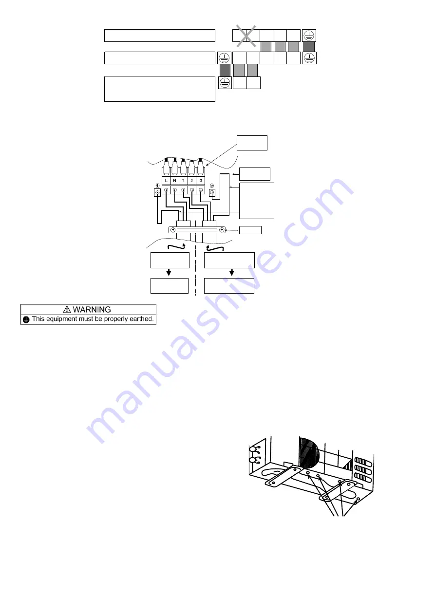
Terminals on the indoor unit

Colour of wires (connection cable)

Terminals on the outdoor unit

Terminals on the isolating devices
(Disconnecting means)

(Power supply cord)

L

N 1

2

3

(L) (N)

1

2

3

L

N


4.  Secure the power supply cord and connection cable onto the control board with the holder. 
5.  Attach the control board cover back to the original position with screw. 
 

Terminal

Board

Control

Board

Earth wire

longer than

others

AC wires

for safety

reason

Holder

Indoor & outdoor

connection cable

Isolating

Devices

Indoor unit

Power supply

cord


  For wire stripping and connection requirement, refer to instruction 

 of indoor unit. 

  Isolating Devices (Disconnecting means) should have minimum 3.0 mm contact gap. 

  Earth wire shall be Yellow/Green (Y/G) in colour and longer than other AC wires for safety reason.


12.3.5  Piping Insulation 

1  Please carry out insulation at pipe connection portion as mentioned in Indoor/Outdoor Unit Installation 

Diagram. Please wrap the insulated piping end to prevent water from going inside the piping. 

2  If drain hose or connecting piping is in the room (where dew may form), please increase the insulation by 

using POLY-E FOAM with thickness 6 mm or above. 

12.3.5.1 

Outdoor Unit Drain Water 

  Water will drip from the base pan hole area 

during defrost function. 

  To avoid water dripping, do not stand or place 

objects at this area. 


Hole


Summary of Contents for CS-HZ9RKE-1

Page 1: ...alth State Territory and local legislation regulations codes installation operation manuals before the installation maintenance and or service of this product WARNING This service information is designed for experienced repair technicians only and is not designed for use by the general public It does not contain warnings or cautions to advise non technical individuals of potential dangers in attem...

Page 2: ...s method for no error code no cooling no warming 59 14 Operation and Control 61 14 1 Basic Function 61 14 2 Indoor Fan Motor Operation 62 14 3 Outdoor Fan Motor Operation 63 14 4 Airflow Direction 64 14 5 Quiet operation Cooling Mode Cooling area of Dry Mode 65 14 6 Quiet operation Heating 66 14 7 Powerful Mode Operation 66 14 8 Timer Control 67 14 9 Auto Restart Control 67 14 10 Indication Panel ...

Page 3: ... product damage burst and serious injury 2 Do not install outdoor unit near handrail of veranda When installing air conditioner unit on veranda of a high rise building child may climb up to outdoor unit and cross over the handrail causing an accident 3 Do not use unspecified cord modified cord joint cord or extension cord for power supply cord Do not share the single outlet with other electrical a...

Page 4: ... force will have impact on the terminal If connection or fixing is not perfect it will cause heat up or fire at the connection 21 Wire routing must be properly arranged so that control board cover is fixed properly If control board cover is not fixed perfectly it will cause heat up or fire at connection point of terminal fire or electrical shock 22 This equipment is strongly recommended to be inst...

Page 5: ...cing please wear hand glove Sharp parts may cause injury 8 Carry out drainage piping as mentioned in installation instructions If drainage is not perfect water may enter the room and damage the furniture 9 Select an installation location which is easy for maintenance Incorrect installation service or repair of this air conditioner may increase the risk of rupture and this may result in loss damage...

Page 6: ...rvice personnel Any qualified person who is involved with working on or breaking into a refrigerant circuit should hold a current valid certificate from an industry accredited assessment authority which authorizes their competence to handle refrigerants safely in accordance with an industry recognised assessment specification Servicing shall only be performed as recommended by the equipment manufa...

Page 7: ...ing the system That there is continuity of earth bonding At all times the manufacturer s maintenance and service guidelines shall be followed If in doubt consult the manufacturer s technical department for assistance If a fault exists that could compromise safety then no electrical supply shall be connected to the circuit until it is satisfactorily dealt with If the fault cannot be corrected immed...

Page 8: ...Hoses or lines shall be as short as possible to minimize the amount of refrigerant contained in them Cylinders shall be kept upright Ensure that the refrigeration system is earthed prior to charging the system with refrigerant Label the system when charging is complete if not already Extreme care shall be taken not to over fill the refrigeration system Prior to recharging the system it shall be pr...

Page 9: ...equipment that is at hand and shall be suitable for the recovery of concerning the equipment that is at hand and shall be suitable for the recovery of flammable refrigerants In addition a set of calibrated weighing scales shall be available and in good working order Hoses shall be complete with leak free disconnect couplings and in good condition Before using the recovery machine check that it is ...

Page 10: ...25 20 Power Level dB 55 Outdoor Noise H L QLo dB A 46 43 Power Level dB 61 Heating Capacity kW 0 85 3 20 6 65 BTU h 2900 10900 22700 kcal h 730 2750 5720 Running Current A 2 70 Input Power W 165 5 70 1 76k COP W W 5 15 5 61 3 78 BTU hW 17 58 19 12 12 90 kcal hW 4 42 4 82 3 25 ErP Pdesign kW 3 0 Tbivalent C 10 SCOP W W 5 2 Annual Consumption kWh 808 Class A Power Factor 92 Indoor Noise H L QLo dB A...

Page 11: ...m3 min ft3 min 9 99 353 Heat m3 min ft3 min 11 41 403 Hi Cool m3 min ft3 min 12 30 435 Heat m3 min ft3 min 15 00 530 SHi Cool m3 min ft3 min 13 46 475 Heat m3 min ft3 min 15 91 562 Outdoor Airflow Hi Cool m3 min ft3 min 33 10 1170 Heat m3 min ft3 min 34 00 1200 Refrigeration Cycle Control Device Expansion Valve Refrigerant Oil cm3 FW50S 450 Refrigerant Type g oz R32 1 12k 39 5 F Gas GWP 675 CO2eq ...

Page 12: ...Bulb 66 2 F Wet Bulb and outdoor air temperature of 35 C Dry Bulb 95 F Dry Bulb 24 C Wet Bulb 75 2 F Wet Bulb 2 Heating capacities are based on indoor temperature of 20 C Dry Bulb 68 F Dry Bulb and outdoor air temperature of 7 C Dry Bulb 44 6 F Dry Bulb 6 C Wet Bulb 42 8 F Wet Bulb 3 Heating low temperature capacity Input Power and COP measured at 230 V indoor temperature 20 C outdoor 2 1 C 4 Heat...

Page 13: ... Noise H L QLo dB A 48 45 Power Level dB 63 Heating Capacity kW 0 85 4 20 7 75 BTU h 2900 14300 26400 kcal h 730 3610 6670 Running Current A 3 95 Input Power W 165 840 2 27k COP W W 5 15 5 00 3 41 BTU hW 17 58 17 02 11 63 kcal hW 4 42 4 30 2 94 ErP Pdesign kW 3 8 Tbivalent C 10 SCOP W W 5 1 Annual Consumption kWh 1043 Class A Power Factor 92 Indoor Noise H L QLo dB A 45 25 18 Power Level dB 61 Out...

Page 14: ...1 Heat m3 min ft3 min 11 79 416 Hi Cool m3 min ft3 min 13 20 465 Heat m3 min ft3 min 15 40 545 SHi Cool m3 min ft3 min 14 11 498 Heat m3 min ft3 min 16 29 575 Outdoor Airflow Hi Cool m3 min ft3 min 34 40 1215 Heat m3 min ft3 min 35 60 1255 Refrigeration Cycle Control Device Expansion Valve Refrigerant Oil cm3 FW50S 450 Refrigerant Type g oz R32 1 12k 39 5 F Gas GWP 675 CO2eq ton Precharged Amount ...

Page 15: ...d outdoor air temperature of 35 C Dry Bulb 95 F Dry Bulb 24 C Wet Bulb 75 2 F Wet Bulb 2 Heating capacities are based on indoor temperature of 20 C Dry Bulb 68 F Dry Bulb and outdoor air temperature of 7 C Dry Bulb 44 6 F Dry Bulb 6 C Wet Bulb 42 8 F Wet Bulb 3 Heating low temperature capacity Input Power and COP measured at 230 V indoor temperature 20 C outdoor 2 1 C 4 Heating extreme low tempera...

Page 16: ...peration o Gas leakage protection o Prevent compressor reverse cycle o Inner protector to protect Compressor o Noise prevention during soft dry operation Operation Improvement o Quiet mode to reduce the indoor unit operating sound o Powerful mode to reach the desired room temperature quickly o 24 hour timer setting o 8 15 C HEAT operation is designed to provide heating at low temperature settings ...

Page 17: ... louver Do not adjust by hand Indicator TIMER 8 15 C HEAT DEICE POWERFUL QUIET POWER e g n a r O e u l B n e e r G n e e r G Orange Orange Green 5 2 Outdoor Unit Air inlet rear Air outlet Air inlet side 5 3 Remote Control AIR CONDITIONER ON OFF SET TIMER CANCEL OFF ON FAN SPEED MODE AIR SWING TEMP OFF ON AIR CONDITIONER TIMER Remote control display ECONAVI operation Operation mode OFF ON Temperatu...

Page 18: ...ight ping hole Air intake direction Air outlet direction 16 4 264 1 Unit mm 870 590 41 61 255 295 60 41 5 60 41 5 Right piping hole Left piping hole 497 2 Indoor unit external dimensions line Installation plate 128 435 127 88 128 435 DISTANCE TO PIPE HOLE CENTER 128 mm DISTANCE TO PIPE HOLE CENTER 128 mm PIPEHOLECENTER PIPE HOLE CENTER 128 241 5 241 5 59 160 AIR CONDITIONER ON OFF SET TIMER CANCEL...

Page 19: ...de View Side View Anchor Bolt Pitch 330 540 Space necessary for installation 100mm 100mm 1000mm Unit mm 3 way valve at Gas side Low Pressure 2 way valve at Liquid side High Pressure 22 124 53 4 330 622 167 97 69 23 61 32 540 160 824 68 5 37 299 ...

Page 20: ...TEMP SENSOR PIPE TEMP SENSOR TANK TEMP SENSOR INTAKE TEMP SENSOR PIPE TEMP SENSOR LIQUID SIDE 2 WAY VALVE 3 WAY VALVE GAS SIDE COOLING HEAT EXCHANGER EVAPORATOR HEAT EXCHANGER CONDENSER HEATING COMPRESSOR 4 WAY VALVE STRAINER EXPANSION VALVE MUFFLER MUFFLER ...

Page 21: ...PHASE POWER SUPPLY 1Ø 230V 50Hz SC TEMPERATURE FUSE M 1 FUSE 103 FUSE 501 FUSE 500 3 1 INDOOR UNIT OUTDOOR UNIT u FUSE 104 PTC 2 NOISE FILTER CT101 REACTOR NTC TH1 RY PWR RY AC PTC1 C103 L N IC19 MS 3 MS 3 FUSE 101 SC 4 WAYS VALVE u FUSE 301 TEMPERATURE FUSE L N ...

Page 22: ...OWER SUPPLY 1Ø 230V 50Hz SC TEMPERATURE FUSE M 1 FUSE 103 FUSE 501 3 1 INDOOR UNIT OUTDOOR UNIT u FUSE 104 PTC 2 NOISE FILTER CT101 REACTOR NTC TH1 RY PWR RY AC PTC1 C103 IC19 MS 3 MS 3 FUSE 101 SC 4 WAYS VALVE u FUSE 301 TEMPERATURE FUSE L N FUSE 500 L N ...

Page 23: ... 5 1 M 5 UP DOWN LOUVER MOTOR INNER FAN MOTOR M 1 7 4 CN FM WHT CN RCV YLW CN RCV WHT B BL Y W R REMARKS B BLUE P PINK BR BROWN O ORANGE BL BLACK Y YELLOW W WHITE G GREEN R RED GR GRAY Y G YELLOW GREEN ELECTRONIC CONTROLLER MAIN ELECTRONIC CONTROLLER FUSE Y G 1 W W R G 2 3 L N BR GR ACN501 GRAY ACN502 WHITE ACL501 BROWN ACL502 BLACK BL BL AC303 WHT AC306 BLK AC304 RED G301 GRN FUSE301 T3 15A L250V...

Page 24: ...TED ON TERMINAL COVER PIPING TEMP SENSOR THERMISTOR CN TH1 WHT CN TANK WHT CN HOT WHT CN STM WHT U RED V BLU W YLW RED BLU YLW COMPRESSOR M COMPRESSOR TEMP SENSOR THERMISTOR ELECTRO MAGNETIC COIL 4 WAY VALVE ELECTRO MAGNETIC COIL EXPANSION VALVE 1 1 1 1 P FUSE 101 T3 15A L250V N Q1 U V W 6 3 3 t t t 4 SWITCHING POWER SUPPLY CIRCUIT FUSE 104 T3 15AL250V ELECTRONIC CONTROLLER TERMINAL BOARD BLK WHT ...

Page 25: ... UP DOWN LOUVER MOTOR OUTER CN STM1 WHT 1 2 3 4 5 16 12V 15 14 13 12 11 10 R47 R46 1 9 2 3 4 5 6 7 8 GND VCC IC03 9 8 7 6 5 4 3 2 1 ELECTRONIC CONTROLLER DISPLAY 5V_ PCB301 CN DISP WHT R303 LED303 LED304 LED305 LED306 LED307 R304 R305 R306 R307 R301 R302 POWER LED301 LED302 TIMER green green orange QUIET orange POWERFUL orange ECONAVI green 8 15 C HEAT blue Deice 12V ELECTRONIC CONTROLLER RECEIVER...

Page 26: ...C188 G2 C187 R313 R312 R311 CN MTR2 WHT AC BLK BLK TERMINAL BOARD 4V e c b D23 D20 R33 R32 Q24 Q26 G2 15V e c b c e b R260 RY HT1 RY HT2 RY FM R284 R211 R278 R277 R259 C174 R47 R43 R11 R12 C88 C10 C9 R42 C64 C69 R1 C5 C63 G6 G6 13V 13V 13V IC4 VCC GND 16 1 9 15 13V 14 13 12 11 10 2 3 4 5 6 7 8 G2 G2 D73 IC5 D75 D74 D76 13V IC5 VCC 16 1 6 5 4 3 2 1 3 1 4 3 2 1 1 3 9 16 15 14 13 12 11 2 3 4 5 6 G2 1...

Page 27: ...ed Circuit Board 11 1 2 Main Printed Circuit Board AC303 RY PWR CN STM1 CN STM2 CN STM4 CN RCV CN DISP CN CNT CN TH CN FM JP1 Random Auto Restart enable disable CN RMT 11 1 3 Indicator Printed Circuit Board LED301 LED302 LED304 LED305 LED307 LED306 CN DISP LED303 ...

Page 28: ...28 11 1 4 Receiver Printed Circuit Board CN RCV 11 1 5 Fuse Printed Circuit Board ACL501 ACN501 ACL502 ACN502 ...

Page 29: ...29 11 2 Outdoor Unit 11 2 1 Main Printed Circuit Board CN TANK CN MTR1 CN S CN HOT CN STM CN MTR2 DATA AC BLK AC WHT CN TH1 CURRENT TRANSFORMER CT POWER TRANSISTOR IPM ...

Page 30: ... If the unit is installed at 10 m distance the quantity of additional refrigerant should be 50 g 10 7 5 m 20 g m 50 g 12 1 3 Indoor Outdoor Unit Installation Diagram Vinyl tape Remote control holder fixing screws 6 Remote control holder 5 Remote control 3 This illustration is for explanation purposes only The indoor unit will actually face a different way 100 mm or more 1000 m m or m ore 100 m m or...

Page 31: ...er using anchor bolts o Always mount the installation plate horizontally by aligning the marking off line with the thread and using a level gauge 2 Drill the piping plate hole with ø70 mm hole core drill o Line according to the left and right side of the installation plate The meeting point of the extended line is the center of the hole Another method is by putting measuring tape at position as sh...

Page 32: ...w steps are done after connecting the outdoor piping and gas leakage confirmation Cover for piping In case of the cover is cut keep the cover at the rear of chassis as shown in the illust ration for future reinstallation Left right and 2 bottom covers for piping How to keep the cover Guide surface Connection cable About 70 80 m m Connection cable Gas side piping Liquid side piping Drain hose Inser...

Page 33: ... of power supply connection to be used indoor power supply or outdoor power supply 12 2 4 1 In case of indoor power supply 1 Install the indoor unit on the installing holder that mounted on the wall 2 Open the front panel and grille door by loosening the screw 3 Cable connection to the power supply through Isolating Devices Disconnecting means Connect approved type polychloroprene sheathed power s...

Page 34: ...ason Holder Holder Indoor outdoor connection cable Isolating Devices Outdoor unit Power supply cord Recommended length mm 55 35 35 50 40 35 60 a b d e f g c 6 8 b c d e f g a 8 Secure the power supply cord and connection cable onto the control board with the holder 9 Close grille door by tighten with screw and close the front panel 12 2 4 2 In case of outdoor power supply 1 Connection cable betwee...

Page 35: ... in colour and longer than other AC wires for safety reason 12 2 4 3 Wire Stripping Connecting Requirement Wire stripping 5 mm or more Conductor over inserted No loose strand when inserted Indoor outdoor connection terminal board 10 1 mm Conductor fully inserted Conductor not fully inserted gap between wires ACCEPT PROHIBITED PROHIBITED WARNING RISK OF FIRE JOINING OF WIRES MAY CAUSEOVERHEATING AN...

Page 36: ...pipe cutter and then remove the burrs 2 Remove the burrs by using reamer If burrs is not removed gas leakage may be caused Turn the piping end down to avoid the metal powder entering the pipe 3 Please make flare after inserting the flare nut onto the copper pipes ...

Page 37: ...lare after inserting flare nut locate at joint portion of tube assembly onto the copper pipe In case of using long piping Connect the piping Align the center of piping and sufficiently tighten the flare nut with fingers Further tighten the flare nut with torque wrench in specified torque as stated in the table Torque wrench Spanner or Wrench 12 3 2 1 2 For connection joint location at inside build...

Page 38: ...cuate the air approximately ten minutes 4 Close the Low side valve of the charging set and turn off the vacuum pump Make sure that the needle in the gauge does not move after approximately five minutes Note BE SURE TO TAKE THIS PROCEDURE IN ORDER TO AVOID REFRIGERANT GAS LEAKAGE 5 Disconnect the charging hose from the vacuum pump and from the service port of the 3 way valve 6 Tighten the service p...

Page 39: ...t 12 3 4 2 In case of outdoor power supply 1 Cable connection to the power supply through Isolating Devices Disconnecting means Connect approved type polychloroprene sheathed power supply cord 3 1 5mm2 type designation 60245 IEC 57 or heavier cord to the terminal board and connect the others end of the cord to Isolating Devices Disconnecting means Do not use joint power supply cord Replace the wir...

Page 40: ...equirement refer to instruction of indoor unit Isolating Devices Disconnecting means should have minimum 3 0 mm contact gap Earth wire shall be Yellow Green Y G in colour and longer than other AC wires for safety reason 12 3 5 Piping Insulation 1 Please carry out insulation at pipe connection portion as mentioned in Indoor Outdoor Unit Installation Diagram Please wrap the insulated piping end to p...

Page 41: ...In 2010 the regulations of American Society of Heating Refrigerating and Air Conditioning Engineers in the United States ANSI ASHRAE34 was issued adopting the grades for refrigerants which are difficult to inflame due to their slow burning rates and as a result have smaller damages in cases of fire The burning rate of R32 is lower by 10cm per second and safety standardization for various usage is ...

Page 42: ...e of R410A it is necessary to do installation and service using high pressure tools and components Table 2 Saturated vapor pressure comparison table Unit MPa Temperature Refrigerant R32 R410A R22 20 0 30 0 30 0 14 0 0 71 0 70 0 40 20 1 37 1 35 0 81 40 2 38 2 32 1 43 60 3 84 3 73 2 33 65 4 29 4 17 2 60 Reference Thermal properties table of Japan Society of Refrigerating and Air Conditioning Enginee...

Page 43: ...tools such as screw drivers metal saws electric drills long nose pliers hole core drills ø70 or ø65 linen tape levels temperature gauges clamp meters electric knives nippers pipe cutters reamers or scrapers spring benders diameters 1 4 3 8 1 2 5 8 monkey wrenches fixing wrenches 17 or 12 mm feeler gauges hexagon wrenches 4 mm testers megohm testers etc Tools used for services Works R32 R410A R22 I...

Page 44: ...izes R32 common R410A R22 Port sizes 1 2 UNF20 7 16 UNF20 5 Charging hoses The pressure resistance of charge hoses is increased At the same time the material is changed to HFC resistant and the size of each manifold adopter is changed as the port size of manifold gauge itself Further some hoses are with anti gas pressure backflow valves placed near the adopters hoses with the valves recommended Ma...

Page 45: ...ame time the digital scale for refrigerant charging is strengthened by receiving the weight of the refrigerant cylinders with four pillars at the corners The connection ports of charging hoses have two separate ports for R22 7 16 UNF20 and R32 R410A 1 2 UNF20 therefore they can be used for the insertion of the existing refrigerants Digital scale for refrigerant charging 9 Refrigerant cylinders Ref...

Page 46: ...for each HCF type can be used Knowledge for the common usage of tools for R410A R32 R410A and R32 machines use different compressor oils If unregulated compressor oil gets mixed into it may cause damage to the machine function Careful pump down will ensure the recovery of compressor oil and it will minimize the remaining amount of the oil in the manifold gauge and charging hose If you only perform...

Page 47: ...vention of impurity Leakage checking Insertion of refrigerant Dismantling indoor outdoor units Repairing by brazing Evacuation Air purging new installation and relocation for at or more than 15 minutes re charging at or more than 60 minutes Indoor outdoor units and piping Displacing pipes and wires and displacing indoor outdoor units Indoor outdoor units installation and piping and wiring Removal ...

Page 48: ... of moisture and dirt do not get into the pipes and make sure of no refrigerant leakage The procedure of flaring and precautions a Cutting of pipes use pipe cutter and cut the pipe slowly not to de shape the pipe b Removal of burrs on the edge of pipe reamer or scraper If the condition of pipe edge after the deburring is no good or if burrs attaches on the flaring it may cause refrigerant leakage ...

Page 49: ...nd leave it for 1 2 minutes Then remove the connection side of the charging hose of vacuum pump adopter after checking the needle of manifold gauge does not turn back 4 Open the stem of 2 way valve to 90 in anti clock wise and close the 2 way valve after 10 seconds and perform gas leakage test 5 Remove the charge hose from the service port of 3 way valve and open the stems of 2 way and 3 way valve...

Page 50: ...ly loosen the charging hose in discharging side of recovery device and perform air purge the recovery cylinder needs slight inside pressure 7 Insert electric plug of recovery device into electrical outlet the fan operation starts 8 Turn the valve 1 and 2 of recovery device to pressure equalization point 9 After a few seconds turn back the valve 1 and 2 to the original position 10 Turn the switch o...

Page 51: ...tach and tighten the caps of two way and three way valves with torque wrench 6 Remove the connecting pipes liquid side and gas side b Removal of indoor and outdoor units 1 Remove the connecting pipes and wires between the indoor and outdoor units 2 Attach capping flare nuts on the edges of the pipes connecting the indoor and outdoor units in order to prevent dust and moisture get into the pipes 3 ...

Page 52: ...ures below 6 Remove the charging hose red of the manifold gauge from the vacuum pump adopter 7 After adjusting the digital scale to zero open the cylinder valve and the valve Lo of the manifold gauge and insert the refrigerant 8 If it is not possible to insert the refrigerant at regulated amount at once operate the cooling mode and gradually insert the refrigerant recommended amount approx 150 g 1...

Page 53: ...side check and make sure no refrigerant is contained in the air be careful with vaporized refrigerant Furthermore protect the compressor terminal with metal plates and heat but use wet clothes to cool down releasing the heat the expansion valves and four way valves prevent destruction of parts In brazing it is important to pour the brazing material without melting the base metal based on capillary...

Page 54: ...rm the provision of gas 1 Slightly open the propane valve of the torch and make sure the gas comes out from the torch crater and then close the propane valve 2 Slightly open the oxygen valve of the torch and make sure the gas comes out from the torch crater and then close the oxygen valve Check there is no gas leakage around the hose connection 13 7 4 Adjustment of flame 1 Slightly open the propan...

Page 55: ... flame Blue color Oxidizing Flame Oxygen is more compared to the neutral flame Although the flame size is small this has the highest flame heat However due to the excessive oxygen contained in the flame the brazing point gets oxidized This flame may cause holes due to the high heat The pipe may get melt White core flame Outer flame Blue orange color 13 7 6 Closing the flame In case of short break ...

Page 56: ...resistance in stainless steel based brazing suitable for brazing tungsten carbide aluminum bronze and copper BCuP BCuP 2 remain 6 8 7 5 approx 710 approx 785 690 815 21 24 5 Cu Good liquidity suitable for brazing copper tube BCuP 3 4 8 5 2 remain 5 8 6 7 approx 645 approx 815 720 815 21 24 5 Cu Suitable for brazing when the joint spacing is not constant BCuP 5 14 5 15 5 remain 4 8 5 3 approx 645 a...

Page 57: ...n Further by bending the brazing portion of dryer side of the capillary tube at 15 mm from the tube top to the angle of about 120 you can prevent the damage of dryer inside and the clogging of brazing material caused by the excessive insertion of capillary tube Gap 0 025 0 05 mm Insert diameter 10 25 mm Inner diameter ø6 45 Outer diameter ø6 35 Brazing material Runny Brazing material Hard to flow ...

Page 58: ... capillary tube and dryer etc caution has to be taken to apply the flame to the dryer side thick pipe side in order to prevent burn out by the heat 4 When brazing the compressor connection pipes suction and discharge remove the sound insulation plate and the fan and place the compressor stand vertically to prevent the leakage of compressor refrigerating machine oil and apply the flame from the com...

Page 59: ... side 3 way valve High temp High pressure Air Mid temp High pressure Liquid Low temp Pressure liquid Low temp Low pressure Air Evaporator EVA FM Fan Fan Capillary tube Indoor unit Temp difference Suction temp Cooling 8 or more Release temp Heating 14 or more Measured after 15 mins with strong fan operation Cooling Gas pressure 0 9 1 2MPa Low temp Low pressure Air Low temp Low pressure liquid Cooli...

Page 60: ...nction Dirty condenser impurity Mixture of air Insufficient evacuation 2 way valve temperature Excess insertion of refrigerant Clogged capillary expansion valve malfunction Compressor malfunction Lack of refrigerant gas 3 way valve temperature Lack of refrigerant gas Compressor malfunction Excess insertion of refrigerant Clogged capillary expansion valve malfunction Suction temperature Release air...

Page 61: ...tting Temperature 16 C 30 C Setting Temperature Limit Checking Min 16 C Max 33 C Internal Setting Temperature Auto Operation Mode Shifting Powerful Mode Shifting Indoor Air Temperature Shifting Outdoor Air Temperature Shifting 14 1 2 Cooling Operation 14 1 2 1 Thermostat control Compressor is OFF when Intake Air Temperature Internal Setting Temperature 1 5 C continue for 3 minutes When compressor ...

Page 62: ...t onwards o If indoor intake temperature remote control setting temperature 3 C if previous operate in DRY mode then continue in DRY mode otherwise COOL mode is decided o If 2 C indoor intake temperature remote control setting temperature 3 C maintain with previous mode o If indoor intake temperature remote control setting temperature 2 C HEAT mode is decided Heat Maintain current mode Cool Dry 6 ...

Page 63: ...n RPM Reduced OFF Indoor Pipe Temp 35o C 39o C 16o C 19o C B Feedback control Immediately after the fan motor started feedback control is performed once every second During fan motor on if fan motor feedback 2550 rpm or 50 rpm continue for 10 seconds then fan motor error counter increase fan motor is then stop and restart If the fan motor counter becomes 7 times then H19 fan motor error is detecte...

Page 64: ...39 Soft Dry Auto 45 70 2 39 Manual 20 25 50 55 70 2 7 17 27 39 1 Automatic vertical airflow direction can be set using remote control the vane swings up and down within the angles as stated above For heating mode operation the angle of the vane depends on the indoor heat exchanger temperature as Figure 1 below It does not swing during fan motor stop When the air conditioner is stopped using remote...

Page 65: ... Direction Patterns at Remote Control Vane Angle 90 65 77 5 102 5 115 14 5 Quiet operation Cooling Mode Cooling area of Dry Mode A Purpose To provide quiet cooling operation compare to normal operation B Control condition a Quiet operation start condition When POWERFUL QUIET button at remote control is pressed twice QUIET will be shown on remote control display b Quiet operation stop condition 1 W...

Page 66: ...peration is shifted to normal operation with previous setting 3 When operation mode is changed quiet operation is shifted to quiet operation of the new mode expect fan fan only mode 4 During quiet operation if timer on activates quiet operation maintains 5 After off when on back quiet operation is not memorised C Control contents a Fan Speed manual 1 Fan speed is changed to Lo b Fan Speed Auto 1 F...

Page 67: ...C 15 0 5 Heating o C 30 min 25 min 35 min 5 14 8 2 OFF Timer Control OFF timer 1 and OFF timer 2 can be set using remote control the unit with timer set will stop operate at set time 14 9 Auto Restart Control 1 When the power supply is cut off during the operation of air conditioner the compressor will re operate within three to four minutes there are 10 patterns between 2 minutes 58 seconds and 3...

Page 68: ...Sensor During ECONAVI operation the sunlight sensor detects sunlight intensity coming through windows and differentiates between sunny and cloudy or night to further optimize energy saving by adjusting the temperature Sunlight judgment is as following Sunlight intensity reset Judge sunlight intensity Judge ambient condition Temperature shift 14 11 1 1 Sunlight Intensity Reset The sunlight intensit...

Page 69: ...itivity Level 1 Less sensitive to sunlight intensity Sensitivity Level 3 Default sensitive level Sensitivity Level 5 More sensitive to sunlight intensity Default Battery insert Set to Level 3 Other than default Display last set data Transmit solar radiation level after 30 secs go back to normal mode Set to Level 4 Press Timer Set to Level 5 Set to Level 1 Set to Level 2 Remote control normal mode ...

Page 70: ...eck code and after 30 seconds return to normal mode Transmit sunlight sensor check code and after 30 seconds return to normal mode Remote control normal mode Operation details o The sunlight sensor check mode will be operated for 5 minutes o During check mode the ON and OFF timer will be memorized but it operation be ignored o During check mode if the sunlight sensor check code is retransmitted th...

Page 71: ...ion error counter will increase by 1 time If the ECONAVI is OFF the 24 hours timer will be reset but the sunlight sensor disconnection error counter will not be reset Error Code judgment o When sunlight sensor disconnection error counter reached 15 times H70 occurred o No TIMER indicator or ECONAVI indicator blinks When error code happened the unit is able to operate without sunlight sensor ...

Page 72: ...fter battery reset default condition set temperature always start with 13 0 C OFF timer activates OFF timer activates OFF timer activates ON timer activates OR ON timer activates OR ON timer activates OR OR OR OR OR OR 1 Summer house set temperature follows previously fixed set temperature 8 0 C 15 0 C Transmit 8 15 C HEAT Go back to previous LCD setting tranmit code Go back to previous LCD settin...

Page 73: ... Dry A 3 43 14 76 5 87 14 76 Cooling Soft Dry B 2 79 5 34 Cooling Soft Dry C 2 79 5 34 Heating 7 37 9 50 4 The first 30 minutes of cooling operation A will be applied Outdoor air temperature 38 5 C 37 5 C A B 15 1 3 IPM Power Transistor Prevention Control A Overheating Prevention Control 1 When the IPM temperature rises to 120 C compressor operation will stop immediately 2 Compressor operation res...

Page 74: ...0 95A During Cooling and Soft Dry operations Indoor suction temperature indoor piping temperature is below 4 C During Heating operations Indoor piping temperature indoor suction is under 5 C b Control contents Compressor stops and restart after 3 minutes If the conditions above happen 2 times within 20 minutes the unit will o Stop operation o Timer LED blinks and F91 indicated 15 1 6 Low Frequency...

Page 75: ...me indoor fan speed will be higher than during its normal operation 4 If indoor heat exchanger temperature is higher than 5 C for 5 minutes the fan speed will return to its normal operation 15 2 4 Freeze Prevention Control 2 1 Control start conditions During Cooling operation and soft dry operation o During thermo OFF condition indoor intake temperature is less than 10 C or o Compressor stops for ...

Page 76: ...ed during COOL or DRY operation During freeze prevention control and timer preliminary operation this control is not applicable o Control content Depends on compressor conditions Compressor OFF Compressor ON The indoor unit fan stops temporarily and then starts to blow at minimum airflow for 30 seconds Compressor ON Compressor OFF The indoor unit fan stops for 90 seconds and then blows at minimum ...

Page 77: ...ce Frequency Limited 15 3 4 Compressor Oil Return Control When compressor starts the compressor will be regulated for 240 seconds 15 3 5 Cold Draught Prevention Control When indoor pipe temperature is low cold draught operation starts where indoor fan speed will be reduced 15 3 6 Deice Operation When outdoor pipe temperature and outdoor air temperature is low deice operation start where indoor fan...

Page 78: ...ing Operation Beep 2 Main unit always continue Test Run forced cooling operation 8 sec Remote Control Number Switch Mode Beep 3 11 sec Remote Control Receiving Sound OFF ON Beep 4 16 sec Auto OFF ON button pressed Press AC RESET at remote control Press AC RESET then any key at remote control Press AC RESET at remote control 3 REMOTE CONTROL NUMBER SWITCH MODE The Remote Control Number Switch Mode ...

Page 79: ...perature range for COOL DRY HEAT mode o Press Set button by using pointer o Press TEMP increment or decrement button to choose No 3 o Press Timer increment or decrement button to select desired temperature low limit of set temperature for COOL DRY mode o Press Timer Set button to confirm low limit selection o Press TEMP increment or decrement button to choose No 4 o Press Timer decrement or increm...

Page 80: ...ol Enable Press SW to enter customer zone press SW s to choose function 10 1 Press SW special setting is immediately cancelled and normal mode starts 2 If no SW is pressed for 30secs then special setting mode is cancelled and normal mode starts 3 Under this function only SW s are effective Note By default is enable ...

Page 81: ...ement 16 2 2 RESET RC To clear and restore the remote control setting to factory default o Press once to clear the memory 16 2 3 RESET AC To restore the unit s setting to factory default o Press once to restore the unit s setting 16 2 4 TIMER To change indoor unit indicator s LED intensity o Press continuously for 5 seconds 16 2 5 TIMER To change remote control display from Degree Celsius C to Deg...

Page 82: ...the refrigeration cycle Such problems include insufficient insulation problem with the power source malfunction of a compressor and a fan The normal outlet air temperature and pressure of the refrigeration cycle depends on various conditions the standard values for them are shown in the table on the right Clogged strainer capillary tube or expansion valve High ...

Page 83: ... Electric current during operation Low Pressure High Pressure Electric current during operation Insufficient refrigerant gas leakage Clogged capillary tube or strainer Short circuit in the indoor unit Heat radiation deficiency of the outdoor unit Inefficient compression Carry out the measurements of pressure electric current and temperature fifteen minutes after an operation is started ...

Page 84: ...power on 2 Press the CHECK button on the remote controller continuously for 5 seconds 3 will be displayed on the remote controller display Note Display only for No transmitting signal no receiving sound and no Power LED blinking 4 Press the TIMER or button on the remote controller The code H00 no abnormality will be displayed and signal will be transmitted to the main unit The power LED lights up ...

Page 85: ...mality Continuous for 5s Outdoor air temperature sensor open or short circuit Outdoor air temperature sensor lead wire and connector H28 Outdoor heat exchanger temperature sensor 1 abnormality Continuous for 5s Outdoor heat exchanger temperature sensor 1 open or short circuit Outdoor heat exchanger temperature sensor 1 lead wire and connector H30 Outdoor discharge pipe temperature sensor abnormali...

Page 86: ... sensor open circuit Check indoor outdoor connection wire and pipe Indoor heat exchanger sensor lead wire and connector Expansion valve lead wire and connector F90 Power factor correction PFC circuit protection 4 times happen within 10 minutes Power factor correction circuit abnormal Outdoor PCB faulty F91 Refrigeration cycle abnormality 2 times happen within 20 minutes Refrigeration cycle abnorma...

Page 87: ...age 230 240V AC power supply abnormal fluctuation NO Defect in communication circuitry Improper connection at terminals Measure the DC voltage at terminal 2 3 communication terminals of outdoor unit terminal board Is the measured DC voltage fluctuate between 18 25V NO Improper connection at terminals NO Measure the AC voltage at terminal 1 2 of indoor unit terminal board Is the measured voltage 23...

Page 88: ... indoor and outdoor units Troubleshooting When abnormality indication starts again Is there any wiring error YES Matched compatibility Correct the indoor outdoor unit connection wires Check the indoor and outdoor unit connection wires Check the spare part numbers of the indoor and outdoor unit PCBs and compare with their Part Lists NO YES NO NO Is indoor unit and outdoor unit model numbers matched...

Page 89: ...heck the indoor intake air temperature sensor Plug out connector from the indoor unit PCB Measure the resistance of the indoor intake air temperature sensor For safety reason and to prevent component breakdown always switch off the power before remove and connect the component Is the measured resistance of the indoor intake air temperature sensor matches the value specified in its characteristic c...

Page 90: ...ressor temperature sensor Plug out connector from the outdoor unit PCB Measure the resistance of the outdoor compressor temperature sensor For safety reason and to prevent component breakdown always switch off the power before remove and connect the component Is the measured resistance of the outdoor compressor temperature sensor matches the value specified in its characteristic chart Check the co...

Page 91: ...Graph In forced cooling check suction ressure Running current and suction pressure is Compressor Lack Compression Replace Compressor Check replace defected CT Running current is much too low and Check for gas leaking source Repair For safety reason and to prevent component break down always switch off the power before remove and connect the component normal Suction pressure and running current is ...

Page 92: ...ts again Turn off power supply and rotate fan by hand Replace fan motor Does fan rotate smoothly Turn power supply on and operate fan Replace indoor PCB Replace fan motor Turn off power supply and disconnect fan motor connector then turn power on NO YES YES NO Does it rotate Check the rotation output from fan motor Is the rotation feedback voltage 5 15Vdc pin 6 4 generated Check the output of fan ...

Page 93: ...ure sensor Plug out connector from the outdoor unit PCB Measure the resistance of the outdoor intake air temperature sensor Defect in outdoor intake air temperature sensor Replace the outdoor intake air temperature sensor Detect in outdoor unit PCB Replace the outdoor unit PCB For safety reason and to prevent component breakdown always switch off the power before remove and connect the component C...

Page 94: ...arts again Check the outdoor air temperature sensor Plug out connector from the outdoor unit PCB Measure the resistance of the outdoor air temperature sensor Is the measured resistance of the outdoor air temperature sensor matches the value specified in its characteristic chart Defect in outdoor air temperature sensor Replace the outdoor air temperature sensor Defect in outdoor unit PCB Replace th...

Page 95: ... temperature sensor matches the value specified in its characteristic chart YES When abnormality indication starts again Check the outdoor heat exchanger temperature sensor Plug out connector from the outdoor unit PCB Measure the resistance of the outdoor heat exchanger temperature sensor Defect in outdoor heat exchanger temperature sensor Replace the outdoor heat exchanger temperature sensor Defe...

Page 96: ... unit PCB Measure the resistance of the outdoor discharge pipe temperature sensor Is the measured resistance of the outdoor discharge pipe temperature sensor matches the value specified in its characteristic chart Defect in outdoor discharge pipe Replace the outdoor discharge pipe temperature sensor Defect in outdoor unit PCB Replace the outdoor unit PCB Check the connector connection Turn off the...

Page 97: ...or unit PCB Measure the resistance of the outdoor discharge pipe temperature sensor Is the measured resistance of the outdoor heat exchanger temperature sensor matches the value specified in its characteristic chart Defect in outdoor discharge pipe Replace the outdoor discharge pipe temperature sensor Defect in outdoor unit PCB Replace the outdoor unit PCB Check the connector connection Turn off t...

Page 98: ...roubleshooting When abnormality indication starts again Is indoor unit and outdoor unit model numbers matched NO Match the compatible model follow specification Check indoor and outdoor units model number Check the indoor and outdoor PCB part number and compare if they matched part list Change for the specified indoor or outdoor unit PCB NO YES Replace the indoor and outdoor unit PCB Caution For s...

Page 99: ...unit PCB Measure the resistance of the outdoor discharge pipe temperature sensor Is the measured resistance of the outdoor gas pipe temperature sensor matches the value specified in its characteristic chart Defect in outdoor discharge pipe Replace the outdoor discharge pipe temperature sensor Defect in outdoor unit PCB Replace the outdoor unit PCB Check the connector connection Turn off the power ...

Page 100: ...B Measure the resistance of the outdoor discharge pipe temperature sensor Is the measured resistance of the outdoor gas pipe temperature sensor matches the value specified in its characteristic chart Defect in outdoor discharge pipe Replace the outdoor discharge pipe temperature sensor Defect in outdoor unit PCB Replace the outdoor unit PCB Check the connector connection Turn off the power Check t...

Page 101: ... unit PCB Measure the resistance of the outdoor discharge pipe temperature sensor Is the measured resistance of the outdoor liquid pipe temperature sensor matches the value specified in its characteristic chart Defect in outdoor discharge pipe Replace the outdoor discharge pipe temperature sensor Defect in outdoor unit PCB Replace the outdoor unit PCB Check the connector connection Turn off the po...

Page 102: ... and rotate fan by hand Does it rotate CN MTR2 WHT IC19 3 5 1 10 14 16 W U V FAN MOTOR MS 3 CN MTR1 PCB BOARD 5 4 3 2 1 C173 5V R105 1k C176 0 01μ 50V G5 R111 1k C177 0 01μ 50V G5 R120 1k C175 0 01μ 50V G5 G5 YES NO YES Turn off power supply and disconnect fan motor CN MRT2 Check resistance of the motor Measure at fan motor connector CN MRT1 1 2 1 3 2 3 Replace outdoor PCB NO Replace fan motor YES...

Page 103: ...dirty Clean the air filter Clean the indoor unit heat exchanger YES Check the dust accumulation on the indoor unit heat exchanger Is the indoor unit heat exchanger dirty Defect in indoor pipe temperature NO Check the indoor pipe temperature thermistor Check the piping installation condition YES Is the measured resistance of the indoor pipe temperature Plug out connector CN TH from the indoor unit ...

Page 104: ...at exchanger dirty Clean the indoor unit heat exchanger Check the dust accumulation on the indoor unit heat exchanger Does it conform to the sensor characteristic chart Check the indoor pipe temperature sensor Replace the indoor pipe temperature sensor Reclaim and recharge with correct amount of refrigerant Replace the indoor unit PCB YES NO NO NO NO YES YES NO YES Check if 2 3 way valve is closed...

Page 105: ...rature Is 4 way solenoid valve being energised 4 way valve not working Check CN HOT Check V coil attach to Check valve v coil Measure voltage For safety reason and to prevent component breakdown always switch off the power before remove and connect the component OK Depending on 4 way valve model YELLOW 2 1 COIL COMPLETE CN HOT WHT YELLOW 4 WAYS VALVE CN HOT VH9 2 4 WAYS VALVE 3 2 1 thermistor Plug...

Page 106: ...nsor Faulty expansion valve Troubleshooting YES YES NO When F17 indication happens Check the system wiring connection Is the wiring connection ok Perform Auto Wiring to correct the Replace the indoor intake air or indoor NO Replace the solenoid coil or expansion YES Check the indoor intake air and indoor pipe temperature sensors Does it conform to the sensor characteristic chart Check the expansio...

Page 107: ...ctuation AC power supply abnormal surge Defect in PFC circuitry Replace the outdoor unit PCB YES 280Vdc Defect in outdoor fan motor Replace outdoor fan motor NO Defect in compressor Replace compressor NO Defect in reactor Replace reactor YES YES Verify PFC abnormality by measuring DC voltage between Is the DC voltage between DCP and DCN normal Confirm the DC voltage between CN FM 1 and 4 when YES ...

Page 108: ... gas amount is OK NO closed When F91 indication happens Check 3 way valve 3 way valve opened Open 3 way valve YES Check for gas leaking source Check for gas leaking source Refer to H16 Gas leaking Check other parts in refrigeration cycles Repair or replace defected part s Re claim and then re charge the right amount Caution For safety reason and to prevent component breakdown always switch off the...

Page 109: ...emove and connect the component Check the U V and W conector connection Turn OFF the power Check the U V and W conector connection at outdoor PCB and compressor terminal Is the connector connection normal From thw disconnected harnesses U V and Disconnect the harnesses U V and W from the compressor terminal Is the blinking of the 6 LEDs in same sequence condition IPM defective Replace outdoor unit...

Page 110: ...diation Reset the error code and turn on the unit Reinstall the outdoor unit Remove the obstacle s Clean the outdoor heat exchanger Is the outdoor fan motor operating Measure the AC DC voltage between pins of connector CN FM outdoor unit PCB Is the voltage supplied to the outdoor NO Defect in outdoor heat exchanger thermistor Replace the outdoor heat exchanger thermistor NO 0V Defect in outdoor un...

Page 111: ...verheats due to defective of outdoor fan motor IPM overheats due to defective of internal circuitry of IPM IPM overheats due to defective IPM temperature sensor Multi Models Only o Compressor OL connector poor contact o Compressor OL faulty Troubleshooting Is outdoor fan motor operating When F96 indication happens For safety reason and to prevent component breakdown always switch off the power bef...

Page 112: ...akdown always switch off the power before remove and connect the component Check the compressor tank temperature sensor Open the 2 3 way valve YES NO Does it conform to the sensor characteristic chart Replace the compressor tank temperature sensor NO YES Check for gas leakage Oil oozing out from the 2 3 way valve Repair the pipe flare or union nuts Reclaim and recharge refrigerant Replace the capi...

Page 113: ...ting Turn off power supply Check the main circuit electrolytic capacitor When F98 indication happens For safety reason and to prevent component breakdown always switch off the power before remove and connect the component Get restarted and measure the input current NO Input current limit Replace the outdoor unit PCB NO YES Normal Check refrigerant amount Repair the pipe flare or union nuts Reclaim...

Page 114: ...re a sound when compressor starts NO Compressor stops YES Outdoor electronic circuit defect due to power transistor short Replace the outdoor unit PCB Amplification IC defect Diode defect Defect in microcontroller Replace the outdoor unit PCB Is compressor vibration even NO Quite a lot of vibration at start operation YES Excessive amount of refrigerant Check the compressor winding resistance Turn ...

Page 115: ...t the capacitor has discharged sufficiently before proceeding with repair work Failure to heed this caution may result in electric shocks 18 1 Indoor Unit 18 1 1 Indoor Electronic Controllers Cross Flow Fan and Indoor Fan Motor Removal Procedures 18 1 1 1 To remove front grille Figure 1 18 1 1 2 To remove electronic controller Figure 2 ...

Page 116: ...ut the electronic controller halfway 8 Remove screw to remove terminal board complete 6 Remove the indicator complete then detach the connectors CN DISP and CN RCV 5 Detach the earth wire screw terminal wire Brown terminal wire Black terminal wire Red and earth wire screw Green AC303 RY PWR CN STM1 CN STM2 CN STM4 CN RCV CN DISP CN CNT CN TH CN FM CN RMT Figure 3 Figure 4 18 1 1 3 To remove discha...

Page 117: ...117 18 1 1 4 To remove control board Figure 6 18 1 1 5 To remove cross flow fan and indoor fan motor Figure 7 ...

Page 118: ...118 Figure 8 Figure 9 ...

Page 119: ...119 Figure 10 ...

Page 120: ...ller be careful of electrostatic discharge 1 Remove the 5 screws of the Top Panel Fig 1 2 Remove the 8 screws of the Front Panel Fig 2 3 Remove the screw of the Terminal Board Cover 4 Remove the Top Cover of the Control Board by 4 hooks Fig 3 5 Remove the Control Board as follows Fig 4 Fig 5 Fig 6 ...

Page 121: ...343 2296 454 18 4 3075 2050 258 2800 1902 347 2515 1779 454 20 13 3 2028 1987 153 1930 1892 254 1834 1798 399 15 8 2043 1742 141 2524 1844 349 2252 1724 452 Dry bulb value based on 46 humidity 19 1 2 CS HZ12RKE 1 CU HZ12RKE 1 Indoor C Outdoor DB C DB WB 16 25 35 TC SHC IP TC SHC IP TC SHC IP 27 19 0 4186 3331 463 3934 3168 630 3500 3007 830 22 0 4672 2522 438 4333 2400 616 3807 2200 821 23 15 7 39...

Page 122: ...4699 1620 5269 1669 5457 1661 20 3344 1515 3950 1650 4100 1570 4820 1560 5653 1672 5995 1661 16 3435 1409 4066 1534 4223 1489 4858 1475 5954 1670 6377 1663 19 2 2 CS HZ12RKE 1 CU HZ12RKE 1 Indoor C Outdoor WB C DB 20 21 15 16 7 8 2 1 7 6 12 11 TC IP TC IP TC IP TC IP TC IP TC IP 24 3665 1851 4264 2016 4635 2030 5479 2087 6141 2153 6360 2143 20 3806 1718 4426 1866 4700 1930 5620 2010 6588 2157 6987...

Page 123: ...High Piping Length 5 0 m Freq Rated Fc 20 1 1 CS HZ9RKE 1 CU HZ9RKE 1 CS HZ9RKE 5 CU HZ9RKE 5 CS AZ9RKE 1 CU AZ9RKE 1 Outdoor Air Temperature C Low Pressure MPa Outdoor Air Temperature C Current A Outdoor Air Temperature C Outlet Air C Low Pressure Psi 138 00 145 00 152 00 160 00 167 00 174 00 1 50 1 70 1 90 2 10 2 30 2 50 2 70 15 20 25 30 35 40 45 0 95 1 00 1 05 1 10 1 15 1 20 15 20 25 30 35 40 4...

Page 124: ...perature C Current A Outdoor Air Temperature C Outlet Air C Low Pressure Psi 123 00 131 00 138 00 145 00 152 00 160 00 2 00 2 50 3 00 3 50 4 00 4 50 5 00 15 20 25 30 35 40 45 50 0 85 0 90 0 95 1 00 1 05 1 10 15 20 25 30 35 40 45 50 11 50 12 50 13 50 14 50 15 50 16 50 17 50 15 20 25 30 35 40 45 50 ...

Page 125: ... 1 CS HZ9RKE 5 CU HZ9RKE 5 CS AZ9RKE 1 CU AZ9RKE 1 Outdoor Air Temperature C High Pressure MPa Outdoor Air Temperature C Current A Outdoor Air Temperature C Outlet Air C High Pressure Psi 174 00 203 00 232 00 261 00 290 00 319 00 1 20 1 40 1 60 1 80 2 00 2 20 2 40 2 60 2 80 25 20 15 10 5 0 5 10 1 20 1 40 1 60 1 80 2 00 2 20 25 20 15 10 5 0 5 10 16 20 24 28 32 36 25 20 15 10 5 0 5 10 ...

Page 126: ... C Current A Outdoor Air Temperature C Outlet Air C High Pressure Psi 1 50 2 00 2 50 3 00 3 50 4 00 4 50 25 20 15 10 5 0 5 10 1 4 1 5 1 6 1 7 1 8 1 9 2 0 2 1 2 2 2 3 2 4 203 00 218 00 232 00 247 00 261 00 276 00 290 00 305 00 319 00 334 00 348 00 25 20 15 10 5 0 5 10 20 24 28 32 36 40 25 20 15 10 5 0 5 10 ...

Page 127: ...1 01 1 02 2 3 4 5 6 7 8 9 10 11 12 13 14 15 16 17 18 19 20 21 22 3 1 0084 5 1 0000 7 5 0 9941 10 0 9859 12 0 9812 15 0 9773 20 0 9698 20 3 2 Heating Capacity Piping Length m Capacity Correction Factor 2 3 4 5 6 7 8 9 10 11 12 13 14 15 16 17 18 19 20 21 22 0 90 0 95 1 00 1 05 1 10 3 1 0041 5 1 0000 7 5 0 9956 10 0 9897 12 0 9853 15 0 9795 20 0 9690 Note The graphs show the factor after added right ...

Page 128: ...8 I I 49 23 B B B 11 19 18 14 21 22 37 20 15 12 16 A A B A A A B B A CWH55025J CWH55051J 8 7 5 9 25 41 26 27 AIR CONDITIONER ON OFF SET TIMER CANCEL OFF ON FAN SPEED MODE AIR SWING TEMP OFF ON AIR CONDITIONER TIMER Note The above exploded view is for the purpose of parts disassembly and replacement The non numbered parts are not kept as standard service parts ...

Page 129: ...ONIC CONTROLLER MAIN 1 ACXA73C08770 O 25 ELECTRONIC CONTROLLER RECEIVER 1 CWA746916 O 26 ELECTRONIC CONTROLLER INDICATOR 1 CWA747110 O 27 ELECTRONIC CONTROLLER FUSE 1 CWA748490 O 28 CONTROL BOARD COVER CASING 1 CWH102456 29 CONTROL BOARD COVER CO 1 CWH13C1286 30 TERMINAL BOARD CO 1 CWA28C2808 O 31 PARTICULAR PLATE FRONT GRILLE 1 CWD912226 32 INDICATOR HOLDER 1 CWD933466 33 FRONT GRILLE COMPLETE 1 ...

Page 130: ...N QTY CS HZ9RKE 1 CS HZ9RKE 5 REMARK 49 INSTALLATION INSTRUCTION DANISH 1 CWF616872 50 AIR FILTER COMPLETE 1 CWD00C1293 Note All parts are supplied from PAPAMY Malaysia Vendor Code 00029488 O marked parts are recommended to be kept in stock ...

Page 131: ...ER MAIN 1 ACXA73C08770 ACXA73C08780 O 25 ELECTRONIC CONTROLLER RECEIVER 1 CWA746916 O 26 ELECTRONIC CONTROLLER INDICATOR 1 CWA747110 O 27 ELECTRONIC CONTROLLER FUSE 1 CWA748490 O 28 CONTROL BOARD COVER CASING 1 CWH102456 29 CONTROL BOARD COVER CO 1 CWH13C1286 30 TERMINAL BOARD CO 1 CWA28C2808 O 31 PARTICULAR PLATE FRONT GRILLE 1 CWD912226 32 INDICATOR HOLDER 1 CWD933466 33 FRONT GRILLE COMPLETE 1 ...

Page 132: ... QTY CS AZ9RKE 1 CS HZ12RKE 1 REMARK 49 INSTALLATION INSTRUCTION DANISH 1 CWF616872 50 AIR FILTER COMPLETE 1 CWD00C1293 Note All parts are supplied from PAPAMY Malaysia Vendor Code 00029488 O marked parts are recommended to be kept in stock ...

Page 133: ...21 22 29 42 26 35 27 2 42 41 15 3 8 7 5 6 4 11 33 28 34 19 1 10 12 39 49 48 51 14 38 50 18 25 24 23 Note The above exploded view is for the purpose of parts disassembly and replacement The non numbered parts are not kept as standard service parts ...

Page 134: ...F BOARD 1 CWH151273 23 SOUND PROOF MATERIAL 1 CWG302952 24 SOUND PROOF MATERIAL 1 CWG302745 25 SOUND PROOF MATERIAL 1 CWG302740 26 ELECTRONIC CONTROLLER MAIN 1 ACXA73C08790R O 27 TERMINAL BOARD ASS Y 1 CWA28K1110J 28 CABINET SIDE PLATE CO 1 CWE04C1481 29 SENSOR COMPLETE OUTDOOR PIPING TEMP 1 CWA50C3079 O 30 CABINET SIDE PLATE L 1 CWE041616A 31 CABINET FRONT PLATE CO 1 CWE06C1441 32 CABINET TOP PLA...

Page 135: ...D PROOF MATERIAL 1 CWG302952 24 SOUND PROOF MATERIAL 1 CWG302745 25 SOUND PROOF MATERIAL 1 CWG302740 26 ELECTRONIC CONTROLLER MAIN 1 ACXA73C08790R ACXA73C08800R O 27 TERMINAL BOARD ASS Y 1 CWA28K1110J 28 CABINET SIDE PLATE CO 1 CWE04C1481 29 SENSOR COMPLETE OUTDOOR PIPING TEMP 1 CWA50C3079 O 30 CABINET SIDE PLATE L 1 CWE041616A 31 CABINET FRONT PLATE CO 1 CWE06C1441 32 CABINET TOP PLATE 1 CWE03114...

Reviews: