background image


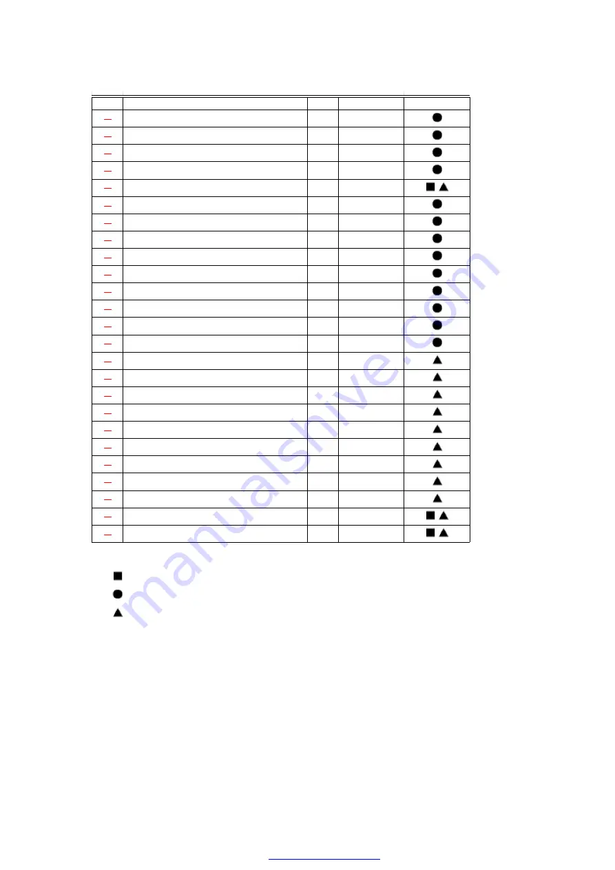
NO

DESCRIPTION & NAME

QTY

CS-280KR

REMARKS

40

CAP (FRONT GRILLE COMPLETE)

4

CWH5060060


41

PARTICULAR PLATE

1

CWH4945610


42

RAIN COVER (HOLDER - EVAPORATOR TUBE ASS’Y

1

CWH4631410


43

BAG COMPLETE (AIR PURIFYING FILTER)

1

CWE4649570C


44

REMOTE CONTROL COMPLETE ASS’Y

1

CWA75C556


45

INSTALLATION PLATE

1

CWH8010540


46

OPERATING INSTRUCTIONS

1

CWF8036900


47

INSTALLATION INSTRUCTIONS

1

CWF8039140


48

BAG COMPLETE - INSTALLATION SCREW

1

CWH4649210


49

SCREW

1

XTT4+12C


50

SCREW

1

XTT4+16C


51

SCREW

1

XTN4+8C 


52

SCREW

1

XTT4+10C


53

SCREW

1

XTT4+8C


54

REMOTE CONTROL UPPER CASE 

1

CWE15C241


55

CONTROL PANEL

1

CWE311064


56

KNOB

1

CWE17196A


57

KNOB

1

CWE17197A


58

CONTACTOR

1

CWA65036C


59

ELECTRONIC CONTROLLER

1

CWA74224


60

INDICATOR

1

CWE39199


61

REMOTE CONTROL LOWER CASE

1

CWE15128A


62

COVER

1

CWB80040A


63

CAP (BUTTON)

1

CWE5060120


64

FUSE COMPLETE

1

CWA4023070C


(Note)

- “   ” marked parts are recommended to be kept in stock. 
- “   ” marked parts are supplied from TAMACO, Taiwan.
- “   ” marked parts are supplied from MACC, Malaysia.

17. Exploded View

70

PDF created with pdfFactory Pro trial version 

www.pdffactory.com

Summary of Contents for CS-A281KR

Page 1: ...Conditioner CS A281KR CU A281KR 2001 Matsushita Air Conditioning Corp Sdn Bhd 183914D All rights reserved Unauthorized copying and distribution is a violation of law 1 PDF created with pdfFactory Pro trial version www pdffactory com ...

Page 2: ...gn Soft Starter Current Auto Restart after Power Failure Long Piping up to 30m Catechin Deodorizing Air Filter Deodorizing Control during operation Cold draught Control 2 Functions 3 Product Specifications 2 PDF created with pdfFactory Pro trial version www pdffactory com ...

Page 3: ...cle Single 240 230 50 Airflow Method OUTLET INTAKE SIDE VIEW TOP VIEW Air Volume Indoor Air Lo m3 min cfm Cooling 14 2 501 Heating 15 6 551 Indoor Air Me m3 min cfm Cooling 15 0 530 Heating 16 4 579 Indoor Air Hi m3 min cfm Cooling 16 3 575 Heating 17 7 625 Outdoor Air m3 min cfm Cooling 59 0 2 083 Heating 59 2 2 090 3 PDF created with pdfFactory Pro trial version www pdffactory com ...

Page 4: ...685 Width inch mm 48 1 32 1 220 34 21 32 880 Depth inch mm 8 21 32 220 13 19 32 345 Net Weight lb kg 40 18 154 70 Compressor Type Scroll type Motor Type Induction 2 poles Rated Output kW Air Circulation Type Cross flow Fan Propeller Fan Material AS Glass Fiber 30 AS Glass Fiber Motor Type Induction 4 poles Induction 4 poles Input W Rated Output W 40 100 Fan Speed Low rpm Cooling 1 262 Heating 1 25...

Page 5: ...r Capillary Tube Length mm Cooling 850 Heating Flow Rate l min Cooling 21 8 Heating 2 ATM Inner Diameter mm Cooling 2 0 Heating Air Filter Material Style A B S Honeycomb Compressor Capacitor F VAC 50 F 370VAC Fan Motor Capacitor F VAC 2 0 F 450VAC 3 0 F 450VAC Specifications are subject to change without notice for further improvement 4 Dimensions 5 PDF created with pdfFactory Pro trial version ww...

Page 6: ...6 PDF created with pdfFactory Pro trial version www pdffactory com ...

Page 7: ...5 Refrigeration Cycle Diagram 6 Block Diagram 7 PDF created with pdfFactory Pro trial version www pdffactory com ...

Page 8: ...7 Wiring Diagram 8 PDF created with pdfFactory Pro trial version www pdffactory com ...

Page 9: ...Operation Details 8 1 Cooling Mode Operation Cooling in operation according to Remote Control setting Time Delay Safety Control 3 minutes 9 PDF created with pdfFactory Pro trial version www pdffactory com ...

Page 10: ...ly if it has stopped for 7 minutes even if the room temperature is below the compressor ON temperature Anti Freezing Control If the temperature of the indoor heat exchanger falls continuously below 2 C for 4 minutes the compressor turns off to protect the indoor heat exchanger from freezing The fan speed setting remains the same Compressor recommences when the indoor heat exchanger temperature ris...

Page 11: ...peed is selected at Remote Control during cooling operation Fan speed rotates in the range of Hi to Me Deodorizing Control Cooling Operation Time Diagram 11 PDF created with pdfFactory Pro trial version www pdffactory com ...

Page 12: ...he Indoor Fan operates with Lo speed Once room temperature reaches below Soft Dry OFF temperature Indoor Fan Compressor and Outdoor Fan Stop for 6 minutes Time Delay Safety Control Once the compressor stops it will not start for 3 minutes during Cooling operation Anti Freezing Control Same as Anti Freezing Control for Cooling Mode operation For 12 PDF created with pdfFactory Pro trial version www ...

Page 13: ... stops Automatic Fan Speed Mode When Automatic Fan Speed is selected at Remote Control during Soft Dry operation Fan speed rotates at Lo speed Deodorizing Control Soft Dry Operation Time Diagram 13 PDF created with pdfFactory Pro trial version www pdffactory com ...

Page 14: ... Control or there is a power failure it restarts after 3 minutes when the Power Switch Remote Control is turned ON or the power supply is resumed When the setting temperature is reached during heating operation the compressor stops and it will not start for 4 minutes 30 minutes Time Saved Control 14 PDF created with pdfFactory Pro trial version www pdffactory com ...

Page 15: ...of Heating mode and after deice Outdoor Fan ON for 90 sec Hi If the Indoor heat exchanger becomes 68 C or more the compressor will stop and restart automatically Time Delay Safety Control 4 minutes waiting 4 way Valve Control 4 way valve ON during Heating operation except deicing operation When the unit is switched to OFF during Heating operation 4 way valve stay at Heating position for 5 minutes ...

Page 16: ...t start operation will be shifted to normal Heating operation Automatic Fan Speed Mode When Automatic Fan Speed is selected at Remote Control during heating operation Fan speed rotates in the range of Hi SLo according to the heat exchanger temperature 16 PDF created with pdfFactory Pro trial version www pdffactory com ...

Page 17: ...Heating Operating Time Diagram 17 PDF created with pdfFactory Pro trial version www pdffactory com ...

Page 18: ...ere is no detection during Outdoor Fan stops Overload Deicing During heating operation if the outdoor Fan OFF duration due to overload control is accumulated up to 60 minutes and after compressor starts for 1 minute deicing starts Deicing ends when a 12 minutes after deicing operation starts b The outdoor piping temperature rises to about 12 C After deicing operation compressor stops for 30 second...

Page 19: ... Automatic Mode Operation 1 When the Automatic Mode Operation is selected the indoor fan operates at SLo fan speed for 20 seconds to sense intake air temperature and determine the 1st operation mode 19 PDF created with pdfFactory Pro trial version www pdffactory com ...

Page 20: ...diate operate only in the first time judgement The present operation mode will be continued if the room temperature does not reach to set temperature Compressor keeps running eventhough after 1 hour from automatic operation mode started For 2nd judgement onwards indoor fan will operate for 20 seconds to sense the intake air temperature for determining operation mode Standard for Determining Operat...

Page 21: ...lower from standard set temperature by pressing the Room Temperature Setting button Operation Higher Standard Lower Mode 2 C 0 C 2 C Cooling 27 C 25 C 23 C Soft Dry 24 C 22 C 20 C Heating 23 C 21 C 19 C 8 5 Sleep Mode Auto Operation Cooling or Soft Dry Operation When you press the SLEEP Mode the following movement will start to avoid overcooling The fan speed refer to Indoor Fan Motor Control The ...

Page 22: ...power failure operation will be automatically restarted when the power is resumed It will start with previous operation mode and airflow direction Time Delay Safety Control is valid Auto Restart Control is not available when Timer or Sleep Mode is set This control can be omitted by cutting the jumper wire J2 Refer Circuit Diagram 8 7 Indoor Fan Speed Control Auto Fan Speed Control When set to Auto...

Page 23: ...to O O O O O O Sleep O O O Hi Me Lo SLo SSLo STOP 8 8 Airflow Direction Control Airflow Direction Auto Control When set a Airflow Direction Auto Control with remote control the louver swings up and down as shown in the diagram The louver does not swing when the Indoor Fan stops during operation When stopped with remote control the discharge vent is closed with the louver 23 PDF created with pdfFac...

Page 24: ... button is pressed the automatic airflow is released and the airflow direction louver move up and down in the range shown in the diagram The louver can be stopped by releasing the button at the desired louver position When the remote control is used to stop the operation the discharge vent is closed with airflow direction louver The left and right airflow direction louvers can be adjusted manually...

Page 25: ... until COMP ON During cold draft c m operation fan speed will be SSLo only SSLo Fan will be running at Lo speed with SSR ON for 0 6 sec and OFF for 5 0 sec 9 Operating Instructions 10 Installation Instructions Required tools for Installation Works 1 Phillips screw driver 5 Spanner 9 Gas leak detector 13 Multimeter 2 Level gauge 6 Pipe cutter 10 Measuring tape 14 Torque wrench 18 N m 1 8 kgf m 65 N...

Page 26: ...ied by the following indication This indication shows the possibility of causing death or serious injury This indication shows the possibility of causing injury or damage to properties The items to be followed are classified by the symbols Symbol with background white denotes item that is PROHBITED from piping Carry out test running to confirm that no abnormality occurs after the installation Then...

Page 27: ...ck or fire 6 Use the specified cable 2 5 mm2 and connect tightly for indoor outdoor connection Connect and clamp the cable so that no external force will be acted on the terminal If connection or fixing not perfect it will cause heat up or fire at the connection 7 Wire routing must be properly arranged so that control board cover is fixed properly If control cover is not fixed perfectly it will ca...

Page 28: ...ase for access for the power disconnection case of emergency In some countries permanent connection of this room air conditioner to the supply is prohibited 1 Power supply connection to the receptacle using a power plug Use an approved 16A power plug with earth pin for the connection receptacle 2 Power supply connection to a circuit breaker for the permanent connection Use an approved 16A circuit ...

Page 29: ...r the door way Ensure the spaces indicated by arrows from the wall ceiling or other obstacles Indoor unit of this room air conditioner shall be installed on the wall in a height of at least 2 5 m OUTDOOR UNIT If an awning is built over the unit to prevent direct sunlight or rain be careful that heat radiation from the condenser is not obstructed There should not be any animal or plant which could ...

Page 30: ...ant should be added as shown in the table Piping length and the elevation Pipe size Max Piping Length A m Max Eleva tion B m Rated Addi tional Refri gerant g m Model Gas Liquid Length Eleva tion A281KR 5 8 1 4 30 25 7 5 5 40 Indoor Outdoor unit installation diagram 30 PDF created with pdfFactory Pro trial version www pdffactory com ...

Page 31: ...a different way 10 2 INDOOR UNIT 10 2 1 SELECT THE BEST LOCATION Refer to Select the best location section 10 2 2 HOW TO FIX INSTALLATION PLATE The mounting wall is strong and solid enough to prevent it from the vibration 31 PDF created with pdfFactory Pro trial version www pdffactory com ...

Page 32: ...late hole with ø70 mm hole core drill Line according to the arrows marked on the lower left and right side of the installation plate The meeting point of the extended line is the centre of the hole Drill the piping hole at either the right or the left and the hole should be slightly slant to the outdoor side 10 2 3 TO DRILL A HOLE IN THE WALL AND INSTALL A SLEEVE OF PIPING 1 Insert the piping slee...

Page 33: ...10 2 4 INDOOR UNIT INSTALLATION 1 For the right rear piping 2 For the right and right bottom piping 3 For the embedded piping 33 PDF created with pdfFactory Pro trial version www pdffactory com ...

Page 34: ...34 PDF created with pdfFactory Pro trial version www pdffactory com ...

Page 35: ... This can be used for left rear piping and left bottom piping also 35 PDF created with pdfFactory Pro trial version www pdffactory com ...

Page 36: ...10 2 5 CONNECT THE CABLE TO THE INDOOR UNIT 1 The inside and outside indoor outdoor connecting cable can be 36 PDF created with pdfFactory Pro trial version www pdffactory com ...

Page 37: ...HD 85PCP AS NZS3191 or heavier cord Ensure the color of wires of outdoor unit and the terminal Nos are the same to the Indoor s respectively Secure the cable onto the control board with the holder clamper INSTALLATION OF AIR PURIFYING FILTERS 1 Open the front panel 2 Remove the air filters 3 Hold the catechin filters by their tabs and install as shown in the 37 PDF created with pdfFactory Pro tria...

Page 38: ...n the three screw covers as shown in the illustration below 3 Remove the five mounting screws 4 Open the front panel and remove a mounting screw at the centre Refer Diagram below 5 To remove the Grille pull the lower left and right side of the grille towards you slightly tilted and lift it straight upwards Two tabs on the top inside edge of the grille are clear of their slots REMOTE CONTROL NO SWI...

Page 39: ...OR UNIT After selecting the best location start installation according to Indoor Outdoor Unit Installation Diagram 1 Fix the unit on concrete or rigid frame firmly and horizontally by bolt nut ø10 mm 2 When installing at roof please consider strong wind and earthquake Please fasten the installation stand firmly with bolt or nails 10 3 3 CONNECTING THE PIPING Connect Piping to Indoor Please make fl...

Page 40: ... tightening the flare nut with torque wrench ensure the direction for tightening follows the arrow on the wrench CUTTING AND FLARING THE PIPING 1 Please cut using pipe cutter and then remove the burrs 2 Remove the burrs by using reamer If burrs is not removed gas leakage may be caused Turn the piping end down to avoid the metal powder entering the pipe 3 Please make flare after inserting the flare...

Page 41: ...gas leakage from the refrigeration cycle Procedure 1 Connect a charging hose with a push pin to the Low and High sides of a charging set and the service port of the 3 way valve Be sure to connect the end of the charging hose with the push pin to the service port 2 Connect the center hose of the charging set to a vacuum pump 3 Turn on the power switch of the vacuum pump and make sure that the needl...

Page 42: ... to 76 cmHg 0 1 MPa in step 3 above take the following measure If the leak stops when the piping connections are tightened further continue working from step 3 If the leak does not stop when the connections are retightened repair the location of leak 10 3 5 CONNECT THE CABLE TO THE OUTDOOR UNIT FOR DETAIL REFER TIO WIRING DIAGRAM AT UNIT 1 Remove the control board cover from the unit by loosening ...

Page 43: ...ith thickness 6 mm or above CHECK THE DRAINAGE 1 Pour a glass of water into the drain tray styrofoam 2 Ensure if water flows out from drain hose of indoor unit DISPOSAL OF OUTDOOR UNIT DRAIN WATER If a drain elbow is used the unit should be placed on a stand which is taller than 3 cm If the unit is used in an area where temperature falls below 0 C for 2 or 3 days in succession it is recommended no...

Page 44: ...ation mode for fifteen minutes or more 2 Measure the temperature of the intake and discharge air 3 Ensure the difference between the intake temperature and the discharge is more than 8 C CHECK ITEMS 44 PDF created with pdfFactory Pro trial version www pdffactory com ...

Page 45: ...inage OK Refer to Check the drainage section Is the earth wire connection properly done Is the indoor unit properly hooked to the installation plate Is the power supply voltage complied with rated value Is there any abnormal sound Is the cooling operation normal Is the thermostat operation normal Is the remote control s LCD operation normal Is the air purifying filter installed 11 3 way Valve 45 P...

Page 46: ...arging cylinder Operation Open Closed Open Closed With valve cap With cap With valve cap With Pumping down Closed Closed Open Open Transferring Clockwise With cap Counter Clockwise Connected manifold Evacuation Open Open Open Open Servicing Counter Clockwise Connected manifold Counter Clockwise Connected gauge gauge Gas charging Open Open Open Open Servicing Counter Clockwise Connected manifold Co...

Page 47: ... Installation When installing an air conditioner be sure to evacuate the air inside the indoor unit and pipes in the following procedure Required tools hexagonal wrench adjustable wrench torque wrenches wrench to hold the joints gas leak detector and charging set The air in the indoor unit and in the piping must be purged If air remains in the refrigeration pipings it will affect the compressor re...

Page 48: ...Hg 0 1 MPa Then evacuate the air for approximately 10 minutes 4 Close the valve of both the Low and High sides of the charging set and turn off the vacuum pump Make sure that the needle in the gauge does not move after approximately 5 minutes BE SURE TO TAKE THIS PROCEDURE IN ORDER TO AVOID REFRIGERANT GAS LEAKAGE 5 Disconnect the charging hose from the vacuum pump and from the service port of the...

Page 49: ...s are retightened repair the location of the leak 11 2 Pumping down Procedure 1 Confirm that both the 3 way valves are set to the open position Remove the valve stem caps and confirm that the valve stems are in the open position Be sure to use a hexagonal wrench to operate the valve stems 2 Operate the unit for 10 to 15 minutes 3 Stop operation and wait for 3 minutes then connect the charge 49 PDF...

Page 50: ...tion Do this quickly so that the gauge ends up indicating 1 to 3 kg cm2G 0 1 MPa to 0 3 MPa 8 Use refrigerant reclaiming equipment to collect refrigerant from indoor unit and pipes 9 Disconnect the charge set and mount both the 3 way valve s stem nuts and the service port caps Use a torque wrench to tighten the service port cap to a torque of 18 N m Be sure to check for gas leakage 10 Disconnect p...

Page 51: ...hen evacuate the air for approximately 10 minutes 4 Close the valve of both Low side and High side of the charging set and turn off the vacuum pump Make sure that the needle in the gauge does not move after approximately 5 minutes BE SURE TO TAKE THIS PROCEDURE IN ORDER TO AVOID REFRIGERANT GAS LEAKAGE 5 Disconnect the charging hose from the vacuum pump 6 Charge the pipes and indoor unit with gas ...

Page 52: ...er continue working from step 3 If the leaks do not stop when the connections are retightened repair the location of the leak 7 Tighten the service port caps of both the 3 way valves at a torque of 18 N m with a torque wrench 8 Remove the valve caps of both the 3 way valves Position both of the valves to open using a hexagonal wrench 4 mm 9 Mount the valve caps onto the 3 way valves 11 4 Balance r...

Page 53: ...1 MPa 1 kg cm2G 3 Connect the charge set s centre hose to refrigerant reclaiming equipment 4 Open the valve Low side on the charge set and loosen the hose connected with the Refrigerant Reclaiming Equipment to purge the air from the hose 5 Turn on refrigerant reclaiming equipment to collect the refrigerant until the needle indicates 0 no refrigerant is remaining 11 5 Evacuation No refrigerant in t...

Page 54: ... for approximately 1 hour vacuum of 4 mmHg or less 3 Close the valve Low side and High side on the charge set turn off the vacuum pump and confirm that the gauge needle does not move approximately 5 minutes after the vacuum pump is turned off 4 Disconnect the charge hose from the vacuum pump 11 6 Gas charging After Evacuation 54 PDF created with pdfFactory Pro trial version www pdffactory com ...

Page 55: ... the charge set and charge the refrigerant to the unit Be sure to open only the High side valve on the charge set to charge the system from the liquid side high presure pipe If the system cannot be charged with the specified amount of refrigerant operate the compressor until the specified amount can be charged and then close the valve at the bottom of the charge cylinder 4 Immediately disconnect t...

Page 56: ...as shown in the Indoor Fan Motor removal procedure 1 Remove the connector CN C of Fan Motor and connector CN STM of stepping motor from the electronic controller Release the earth wire YELLOW GREEN from the control board terminal and sensors from its holders Refer 2 Remove the Control Board As shown in remove the 5 screws Pull the control board forward slightly Caution Remove of Discharge Grille b...

Page 57: ...wn and forward direction 4 Remove the Indoor Fan Motor Loosen the Fan Mounting Screw at the junction with Cross Flow Fan Loosen the screw at the left side of the evaporator Pull off the Bearing at the left of the Cross Flow Fan Fig 4 Fig 5 57 PDF created with pdfFactory Pro trial version www pdffactory com ...

Page 58: ...Pull the left side of the evaporator forward slightly and remove the cross Flow Fan B Disassembly of the parts Outdoor Unit Inspection points for the Outdoor Electronic Controller 1 The Electronic Controller Can be seen by removing the cabinet Top plate and Front plate as shown in the Fig 8 58 PDF created with pdfFactory Pro trial version www pdffactory com ...

Page 59: ... the remote control might not work If this happen remove the back cover of the remote control and you will find a resetting terminal and by shorting it with a minus screwdriver it will return to normal Changing the wireless remote control transmission code When two indoor units are installed in the same room in order to 59 PDF created with pdfFactory Pro trial version www pdffactory com ...

Page 60: ...is set to A when it is shipped By adding a jumper wire to the remote control side and CUTTING J RA J RB to the indoor printed circuit board it is possible to select from 4 types of transmission codes including one at time of delivery condition 1 60 PDF created with pdfFactory Pro trial version www pdffactory com ...

Page 61: ...ose malfunctions make sure that there are no electrical problems before inspecting the refrigeration cycle Such problems include insufficient insulation problem with the power source malfunction of a compressor and a fan The normal outlet air temperature and pressure of the refrigeration cycle depends on various conditions the standard values for them are shown in the table to the right 61 PDF cre...

Page 62: ...13 1 1 Relationship between the condition of the air conditioner and pressure and electric current 62 PDF created with pdfFactory Pro trial version www pdffactory com ...

Page 63: ...as leakage Clogged capillary tube or Strainer Short circuit in the indoor unit Heat radiation deficiency of the outdoor unit Inefficient compression Carry out the measurements of pressure electric current and temperature fifteen minutes after an operation is started 13 1 2 Diagnosis methods of a malfunction of a compressor and 4 way valve 63 PDF created with pdfFactory Pro trial version www pdffac...

Page 64: ...c current reaches a high level abnormally and the value exceeds the limit of an ammeter some cases a breaker turns off Locked compressor The compressor is a humming sound Electric current during operation becomes approximately 80 lower than the normal value Inefficient switches of the 4 way valve The temperature difference between from the discharge tube to the 4 way valve and from tube to the 4 w...

Page 65: ...24 5 43 3 02 19 0 C 8 00 2 65 19 5 C 8 60 5 98 2 46 8 16 5 67 2 65 7 60 5 64 2 84 6 96 5 42 3 05 22 0 C 9 61 5 62 2 50 9 04 4 99 2 68 8 40 4 44 2 90 7 68 3 89 3 10 TC Total Cooling Heating Capacity kW Indoor 27 C 19 C SHC Sensible Heat Capacity kW Outdoor 35 C 24 C IP Input Power kw 65 PDF created with pdfFactory Pro trial version www pdffactory com ...

Page 66: ...66 PDF created with pdfFactory Pro trial version www pdffactory com ...

Page 67: ...15 Exploded View 67 PDF created with pdfFactory Pro trial version www pdffactory com ...

Page 68: ...16 Replacement Parts List Model CS A281KR 68 PDF created with pdfFactory Pro trial version www pdffactory com ...

Page 69: ...4017690 20 CIRCUIT ASS Y OPERATION BUTTON COMPLETE 1 CWA3919420 D K 21 CIRCUIT ASS Y RECEIVER COMPLETE 1 CWA3919420 C K 22 CIRCUIT ASS Y DISPLAY COMPLETE 1 CWA3919420 B K 23 CIRCUIT ASS Y ELECTRONIC CONTROLLER 1 CWA3919420 A K 24 TERMINAL BOARD ASS Y 1 CWA4706600K 25 SCREW 1 XTT4 14C 26 POWER SUPPLY COMPLETE 1 CWA4102330C 27 TERMINAL BOARD COMPLETE 1 CWA4706620C 28 SENSOR COMPLETE 1 CWA3900230C 29...

Page 70: ...CREW 1 XTT4 12C 50 SCREW 1 XTT4 16C 51 SCREW 1 XTN4 8C 52 SCREW 1 XTT4 10C 53 SCREW 1 XTT4 8C 54 REMOTE CONTROL UPPER CASE 1 CWE15C241 55 CONTROL PANEL 1 CWE311064 56 KNOB 1 CWE17196A 57 KNOB 1 CWE17197A 58 CONTACTOR 1 CWA65036C 59 ELECTRONIC CONTROLLER 1 CWA74224 60 INDICATOR 1 CWE39199 61 REMOTE CONTROL LOWER CASE 1 CWE15128A 62 COVER 1 CWB80040A 63 CAP BUTTON 1 CWE5060120 64 FUSE COMPLETE 1 CWA...

Page 71: ...18 Replacement Parts List Model CU A281KR 71 PDF created with pdfFactory Pro trial version www pdffactory com ...

Page 72: ...UID 1 CWB4034150 18 3 WAYS VALVE GAS 1 CWB4034170 19 4 WAYS VALVE ASS Y 1 CWB4034590K 20 TUBE ASS Y CAPILLARY TUBE CHECK VALVE 1 CWB5932090 21 STRAINER 1 CWB4042340 22 V COIL COMPLETE 1 CWA4019380C 23 CONTROL BOARD ASS Y 1 CWH4712690 24 CAPACITOR FAN MOTOR 1 CWA4069960 25 CAPACITOR COMPRESSOR 1 CWA4069780 26 HOLDER CAPACITOR 1 CWH4828750 27 TERMINAL BOARD ASS Y 1 CWA4706590 28 ELECTRONIC CONTROLLE...

Page 73: ...1 CWE5030720A 48 CABINET REAR PLATE COMPLETE 1 CWE5030820ACA 49 CABINET FRONT PLATE ASS Y 1 CWE5030640K 50 WIRE NET REAR 1 CWE4537530A 51 HOLDER CAPACITOR 1 CWH4828800 52 HOLDER PS CORD 1 CWH4627100 53 MUFFLER 1 CWB6040210 Note marked parts are recommended to be kept in stock marked parts are supplied from TAMACO Taiwan marked parts are supplied from MACC Malaysia 19 Electronic Parts List Electron...

Page 74: ...IODE E4060 020T ZD1 ZENER DIODE C4082 100T ZNR1 ZNR2 ZNR3 ZNR C4084 150 RY HOT RELAY ELECTRO MAGNETIC C4104 180 RY HI ME LO RELAY ELECTRO MAGNETIC C4104 170 RY COMP RELAY ELECTRO MAGNETIC C4076 310 SSR1 SSR C4092 060 SW1 SW2 PUSH SWITCH C4001 200 FUSE FUSE XBA2C31TR0 X1 RESONATOR F4090 010T BZ BUZZER SOUND GENERATOR C4091 030 Q6 Q8 TRANSISTOR C4086 250T Note All parts are supplied from TAMACO Taiw...

Page 75: ... A59014 RY HOT RELAY A00160 RY DEICE RELAY A00160 RY OFF RELAY A00160 RY H L RELAY A00160 RY V RELAY A00160 FUSE FUSE XBA2C31TR0 X1 RESONATOR A45ST4 0MGWT Note All parts are supplied from MACC Malaysia Vendor Code 086 Electronic Controller C3919 400 CU A281KR SYMBOL DESCRIPTION NAME PART NO IC1 IC2 INTEGRATED CIRCUIT J4083 070 Q1 Q2 TRANSISTOR C4086 250T D1 D5 D7 DIODE E4060 020T RY C RY L RELAY E...

Page 76: ...How to use electronic circuit diagram 76 PDF created with pdfFactory Pro trial version www pdffactory com ...

Page 77: ...2 sec Anti Freezing Control 4 min 0 sec Mode Judgement 20 sec 0 sec Soft Dry Off 6 min 36 sec On 10 min 60 sec SOFT DRY 10 min operation Deodorizing Control 40 sec 4 sec Comp ON Cooling 70 sec 7 sec Comp ON 20 sec 2 sec Comp OFF 180 sec 18 sec Comp OFF Soft Dry 40 sec 4 sec Comp ON 360 sec 36 sec Comp OFF Indoor Fan Step Change 1 sec 0 sec After Deice Ended 30 sec 3 sec Comp OFF F Motor ON 4 Way v...

Page 78: ...20 1 REMOTE CONTROL MACC Printed in Malaysia 78 PDF created with pdfFactory Pro trial version www pdffactory com ...

Reviews: