

3
Connections
1
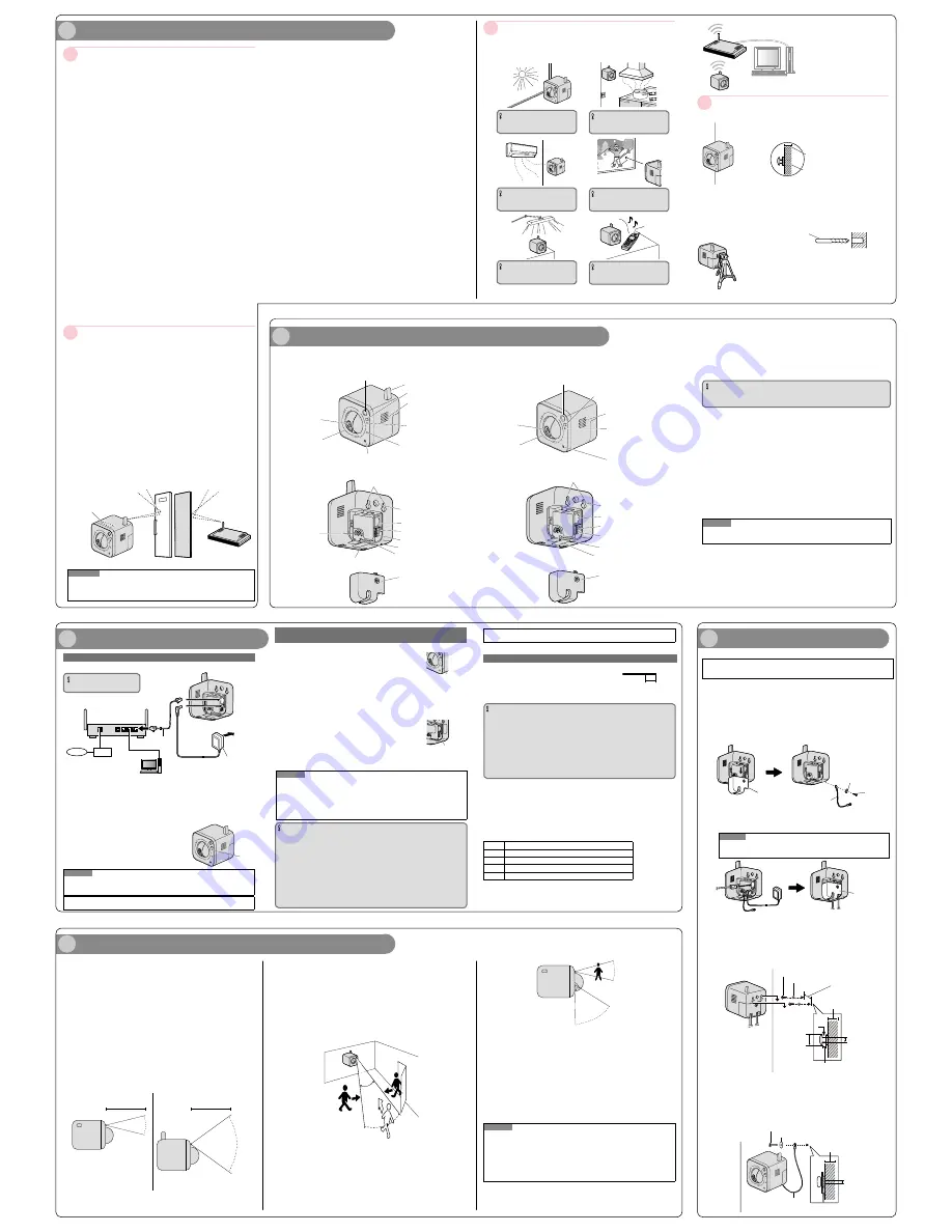
Check the installing place
2
Major operating controls
Determining the mounting position
Precautions for Installation
About the range of use for wireless communication
(BL-VT164W, BL-VT164WE, BL-VT164WU)
¢
Installing the camera on the wall
Make sure the flexible stand is firmly mounted on a beam of wood (25 mm
{31/32 inches} and greater) etc. When there is no beam, apply a board on
the other side of the wall to make sure the camera does not drop.
When mounting on a mortar or concrete surface
Prepare anchors for 4 mm {5/32 inches} diameter screws for mounting.
Mortar walls break easily when drilling. Be careful of pieces of mortar
which may become loose and fall.
1. Place the flexible stand on the wall where you plan to mount the flexible
stand and mark the points where you are going to make holes.
2. Make holes with an electric drill. Insert anchors (locally procured)
into the holes and push them inside the holes with a hammer.
3. Mount the flexible stand using the screws.
Drill for concrete (in case of
tile, use a drill for tile)
Determining how to mount the camera
¢
Tripod Mount
Do not use a tripod screw with a thread of 6 mm {1/4 inches} or more.
This may damage the tripod mounting hole.
The camera cannot be mounted depending on the shape of the camera
platform.
* When the camera is installed to a tripod mount, because the center of
gravity is moved forward, the tripod may fall over.
Beam of wood
At least 25 mm {31/32 inches}
The camera's built-in Body Heat Sensor is a pyroelectric infrared sensor, which may
not perform properly in the following areas. Avoid these kinds of locations when
mounting the camera.
(This illustration represents BL-VT164W.)
IMPORTANT
Where the camera or the object is
exposed to direct sunlight
IMPORTANT
In a greasy or humid place such as a
kitchen
IMPORTANT
Where there are sharp temperature
changes such as near an air conditioner
IMPORTANT
Where there is an obstacle such as
glass in front of the camera
IMPORTANT
Where the camera or the object is
exposed to bright light
IMPORTANT
Near devices that emit radio waves,
such as mobile phones
Panasonic assumes no responsibility for injuries or property damage resulting
from failures arising out of improper installation or operation inconsistent with
this documentation.
This camera is designed to be used indoors.
This camera is not operable outdoors.
Do not expose this camera to direct sunlight for hours and do not install the product
near a heater or an air conditioner. Otherwise, it may cause deformation, discoloration
and malfunction. Keep this camera away from water and moisture.
Do not place this product in the following places:
Locations where it may get wet from rain or water splash
Locations where a chemical agent is used such as a swimming pool
Locations subject to humidity, dust, steam and oil smoke
Locations that have a specific environment that is subject to an inflammable atmosphere or solvents
Locations where a radiation, an X-ray, a strong radio wave or a strong magnetic field
is generated
Locations where corrosive gas is produced, Locations where it may be damaged by
briny air such as seashores
Locations where the temperature is not within the specified range (0 °C to +40 °C
{32 °F to +104 °F}).
Locations subject to vibrations (This product is not designed for on-vehicle use.)
Locations subject to condensation as the result of severe changes in temperature
Be sure to remove this product if it is not in use.
Before installation
When this camera is mounted on a wooden wall, use the wood screws (accessory,
Screw B). Screws to be used for other materials are not provided. Prepare the screws
according to the material, structure, strength and other factors of the mounting area and
the total weight of objects to be mounted.
Ensure that the mounting surface, anchor and screws are sufficiently strong.
Do not mount this product on a plaster board or a wooden section because they are
too weak. If this product is unavoidably mounted on such a section, the section shall
be sufficiently reinforced.
Design and engineer the power supply system to turn on/off the power
of this product.
The product has no power switch. When installing the product, disconnect the AC
adaptor and use a power supply device equipped with the ON-OFF switch for servicing.
About the network connection
When connecting to a network using the network cable of this product, observe the fol-
lowing. When wiring for the network, design and engineer not to be affected by thunder.
Screw tightening
The screws must be tightened with an appropriate tightening torque according to
the material and strength of the installation area.
Do not use an impact driver. Use of an impact driver may damage the screws or
cause tightening excessively.
When a screw is tightened, make the screw at a right angle to the surface. After tightening
the screws, perform visual check to ensure tightening is enough and there is no backlash.
Fall prevention measures
When the external safety wire is connected, select a connection point resulting in that
nothing will hit people after the stand is damaged.
Do not remove or loosen the internal camera screws.
Do not loosen the internal camera screws. Otherwise, water exposure may cause
damage or malfunction of camera, or camera dropping may result in injury.
Radio disturbance
When this product is used near TV/radio antenna, strong electric field or magnetic field
(near a motor, a transformer or a power line), images may be distorted and noise
sound may be produced.
Router
When connecting this product to the Internet, use a broadband router with the port for-
warding function (NAT, IP masquerade). Refer to the Operating Instructions (included in
the CD-ROM) for further information about the port forwarding function. Configure the
wireless settings of the camera to match the wireless settings of the router. For infor-
mation on the wireless settings of the router, refer to the operating instructions included
with your wireless router.
Time & date setting
It is necessary to set the time & date before putting this product into operation. Refer to
the Operating Instructions on the provided CD-ROM for descriptions of how to perform
the settings.
About the [INITIAL SET] button
After turning off the power of the camera, turn on the power of the camera while holding down
this button, and wait for around 5 seconds or more without releasing this button. Wait around
3 minutes after releasing the button. The camera will start up and the settings including the
network settings will be initialized. Before initializing the settings, it is recommended to write
down the settings in advance. The initialization will be complete when the POWER indicator
stops blinking orange and lights off. Note that the preset position settings and the CRT key
(SSL encryption key) used for the HTTPS protocol will not be initialized.
IMPORTANT
Do not turn off the power of the camera during the process of initialization. Otherwise,
it may fail to initialize and may cause malfunction.
About the [PRIVACY] button
Privacy mode allows you to protect your privacy by hiding the lens inside the camera, prevent-
ing camera images from being seen. You can turn privacy mode on by pressing the PRIVACY
button on the front of the camera.
When privacy mode is turned on, the PRIVACY button (which also serves as the camera’s
POWER indicator) changes from green to red to let you know that privacy mode is activated.
To turn privacy mode off and allow the camera to be accessed, simply press the PRIVACY
button again. It should turn green within a few seconds.
If users are accessing the camera when privacy mode is turned on, the camera image area
displayed in their web browsers turns into a black image display. No camera pages can be
accessed by users while privacy mode is turned on. Once privacy mode is turned off, users
can press the refresh button in their web browsers to view images again.
The camera’s administrator can also turn privacy mode on and off using a PC or a mobile
phone, and the PRIVACY button itself can be disabled so that privacy mode cannot be turned
on or off by pressing the PRIVACY button.
For more information about privacy mode, see Privacy Mode in the Operating Instructions
(included in the CD-ROM).
Note
If you plan on using the PRIVACY button to turn privacy mode on and off, make sure you
mount the camera where you can reach the button.
About the POWER indicator and the WIRELESS indicator (WPS indicator)
For more information, see Configure the basic settings [Basic] in the Operating Instructions
(included in the CD-ROM).
Built-in Body Heat Sensor
(pyroelectric infrared sensor)
<BL-VT164W/BL-VT164WE/BL-VT164WU>
Antenna
PRIVACY button
POWER indicator
WIRELESS indicator (WPS indicator)
Wall mounting holes
Tripod mounting hole
Serial number and MAC
address label
External I/O interface
DC IN jack
LAN port
WIRELESS button (WPS button)
INITIAL SET button
Cable cover
<Rear View>
Lens cover
Lens
Speaker
Microphone
Safety wire hole
<BL-VT164/BL-VT164E/BL-VT164U>
Notes About the Camera’s Built-in Body Heat Sensor
(This illustration represents BL-VT164W.)
Please read the following information about the camera’s built-in Body Heat Sensor (Pyroelectric
infrared sensor) before deciding where to mount the camera.
Refer to the Panasonic Network Camera website at
http://panasonic.net/pss/security/support/info.html for further information
about the built-in Body Heat Sensor.
The camera’s built-in Body Heat Sensor is a pyroelectric infrared sensor, which means it uses
infrared rays to detect temperature differences within its range that are emitted naturally by people,
animals, etc. The sensor can be used to trigger the camera to buffer (i.e., temporarily store) camera
images in its memory. You can view these images later as desired. The sensor can also be used to
trigger the camera to transfer images to someone or somewhere, by FTP, E-mail, or HTTP.
Because the detection range is easily affected by the temperature of the surrounding environment
or how fast the objects in front of the camera are moving, you should take the following into con-
sideration when deciding where to mount the camera.
1
The sensor’s active detection range is about 5 m {3/16 inches} in front
of the camera, about 28º horizontally, and about 71º vertically, when
the camera is in a 20 ºC (68 ºF) environment.
2
If an object is within about 1 m {1/32 inches} of the camera, the sensor
may detect the object even if it is outside of the sensor’s range.
4
Choosing a Location to Mount the Camera
3
If there is no temperature difference between objects in range of the
camera’s sensor and the surrounding environment, such as on a hot
summer day, the sensor may not be able to detect properly.
4
If the sensor is obstructed, the sensor is not able to make detections.
Remove any obstacles in front of the sensor.
5
As shown in the illustration below, the sensor can easily detect
temperature differences of objects moving sideways within the detection
range, but cannot easily detect objects moving slowly towards the sensor.
Mount the camera where objects often pass the camera from the sides.
6
If the lens is aimed at an area outside of the sensor’s active detection
range, the objects that trigger the sensor may not be visible, and therefore
buffered or transferred images may not show the object that triggered the
sensor.
In the example below, the person has triggered the sensor, but the person is not in the
visible range of the camera.
We recommend that you limit the pan and tilt range of the camera to the active detec-
tion range of the sensor, or that you limit other user’s access to the pan and tilt features.
7
The sensor may not perform properly in some areas.
Refer to “Determining the mounting position” when mounting the camera.
8
When deciding where to mount the camera, you can verify the sensor’s
ability to make detections that satisfy your needs by referring to the
camera’s POWER indicator. See Configure the basic settings [Basic] in
the Operating Instructions (included in the CD-ROM), and configure the
camera to light the POWER indicator in orange when the sensor makes
a detection. You can then adjust the sensitivity of the sensor (see
Configure the settings relating to the alarm action [Alarm] in the
Operating Instructions (included in the CD-ROM)) or change the
camera’s location if necessary. Note that if you increase the sensitivity of
the sensor, the sensor may make inaccurate detections.
Note
If you are not satisfied with the sensor’s ability to make detections, we recommend using
the camera’s motion detection feature. This feature detects motion by detecting changes in
the camera image. For more information, see Configure the VMD settings [VMD area] in the
Operating Instructions (included in the CD-ROM).
The built-in sensor and the motion detection feature are not designed to be used for securi-
ty or surveillance. No responsibility will be taken by our company with respect to conse-
quences resulting from the use of these features.
Easy to detect
Easy to detect
Difficult to detect
(The detection range may
be reduced)
About 5 m
{3/16 inches}
About 5 m
{3/16 inches}
About 28°
About 71°
Top View
Side View
28º
57º
5
Mounting the Camera
Before installing the camera, check that the camera settings have been
completed. Refer to “Configure the settings of the camera” (leaflet).
Installing the camera on the wall
(This illustration represents BL-VT164W.)
Adjust the camera to a suitable position/direction while confirming the images actually displayed
on the computer screen.
1
Remove the cable cover, secure the safety wire to the camera
using screw B (accessory) and washer M (accessory).
(Recommended tightening torque: 1.6 N·m {1.18 lbf·ft})
Make sure you attach the safety wire when mounting the camera, to prevent the
camera from falling.
3
Mount the camera on the screws by inserting the screws into the
camera’s wall mounting holes, then sliding the camera down until
it is secure. (Minimum pull-out strength: 294 N {66.09 lbf})
Leave 2 mm {3/32 inches} of space between the screw heads and the washers, as
shown below.
4
Secure the safety wire to the wall using screw A (accessory) and
washer L (accessory). (Minimum pull-out strength: 294 N {66.09 lbf})
Leave some slack in the safety wire, as shown.
Attach the safety wire in a position so that if the camera were to become
detached, it would not fall on nearby people.
2
Connect a LAN cable and the AC adaptor cord to the camera and
attach the cable cover.
Insert the LAN cable until it clicks into to place.
Note
BL-VT164W/BL-VT164WE/BL-VT164WU:
A LAN connection is not needed when using the camera in wireless mode.
Cable cover
Safety wire
(accessory)
Washer M (accessory)
Screw B
(accessory)
Washer S (accessory)
Screw C (accessory)
29 mm
{1-5/32 inches}
At least 25 mm
{31/32 inches}
2 mm
{3/32 inches}
3.5 mm
{5/32 inches}
9 mm
{11/32 inches}
Washer L (accessory)
Screw A (accessory)
At least 25 mm
{31/32 inches}
4 mm
{5/32 inches}
Safety wire
Cable cover
1
Connect the LAN cable to the camera and the router.
When connecting the camera to a wireless LAN, refer to “When connecting the cam-
era using a wireless LAN”.
2
Connect the AC adaptor cord to the DC IN jack.
3
Connect the AC adaptor to the camera and plug the AC adaptor into
the power outlet.
Confirm that the POWER indicator turns green after
about 1 minute. If it does not turn green, see the
Troubleshooting Guide on the CD-ROM.
When you operate the camera, the power outlet
should be near the camera and easily accessible.
Use only specified Panasonic AC adaptor.
The camera may become warm. This is normal.
Green
WAN
4 3 2 1
LAN
Router
Internet
Modem
PC
LAN cable
(Cat-5 straight cable)
AC adaptor
To the
power
outlet
When connecting the camera to your router
IMPORTANT
Use a 4-pair UTP/STP cable.
(This illustration represents BL-VT164W.)
<Front view>
(This illustration represents BL-VT164W.)
When using a wireless connection, con-
figure the wireless settings for the cam-
era and the wireless router before install-
ing the camera.
Confirm in advance that the camera can
connect with the wireless router from its
installed place. Refer to “3 Connections”
for further information.
Do not use this product in the following areas or locations.
(It may cause interference to radio communications or malfunction.)
Indoor areas that have specified radio stations or mobile communications
equipment
Locations near microwave ovens or Bluetooth devices
Indoors areas that use antitheft devices or 2.4 GHz frequency devices such as
POS systems
Change the installation location of the camera when there are materials or
objects such as the following between the camera and a wireless router.
(When there are materials or objects that are difficult for radio waves to pass through in
the installation area, wireless transmission may fail or the transmission speed may
become slower.)
(When there are materials or objects that reflect radio waves in the installation area,
wireless transmission may fail or the transmission speed may become slower due to
interference from reflected radio waves.)
A metallic door or shutter
A wall with an insulation material that contains aluminum foil
A wall made of concrete, stone or brick
Several walls separated by open space
A wall made of tin
A steel shelf
Fireproof glass
A steel door
A reinforced concrete wall
Internal Antenna
Note
When two or more radio routers and radio interference exist, radio may become being hard
to be connected or transmission speed may become remarkably slow. In that case, it may
be necessary to change the channel of a radio router or to rearrange wireless applications.
Note
The camera operates in wireless mode when the camera is turned on without the LAN
cable connected or with the power of the router turned off. Recheck the LAN cable con-
nection and the power to the router, and then turn the camera on or off.
External I/O terminals
Connect external devices to the EXT I/O terminal.
When connecting an external device, remove 9 mm - 10 mm
{11/32 inches - 13/32 inches} of the outer jacket of the cable
and twist the cable core to prevent the short circuit first.
Specification of cable (wire): 22 AWG - 28 AWG
Single core, twisted
IMPORTANT
Do not connect 2 wires or more directly to a terminal. When it is necessary to connect 2
or more wires, use a splitter.
Input and output of the external I/O terminal 2 and 3 can be switched by configuring the
setting. The default of EXT I/O terminal 2 is "ALARM IN 2" and of EXT I/O terminal 3 is
"ALARM IN 3". It is possible to determine whether or not to receive input from EXT I/O
terminal 2 and 3 (ALARM IN2, 3) by selecting "Off", "Alarm input", "Alarm output" or "AUX
output" for "Terminal alarm 2" or "Terminal alarm 3" on the [Alarm] tab on the "Alarm setup"
page. Refer to the Operating Instructions (included in the CD-ROM) for further information.
The default of EXT I/O terminals is "Off". When "Off" is selected, it is possible to connect
external devices as well as the input setting.
When using the EXT I/O terminals as the output terminals, ensure they do not cause
signal collision with external signals.
Strip range
Approx. 9 mm - 10 mm
{11/32 inches - 13/32 inches}
<Ratings>
ALARM IN1, ALARM IN2, ALARM IN3
Input specification : No-voltage make contact input (4 V - 5 V DC, internally pulled up)
OFF
: Open or 4 V - 5 V DC
ON
: Make contact with GND (required drive current: 1 mA or more)
ALARM OUT, AUX OUT
Output specification : Open collector output (maximum applied voltage: 20 V DC)
Open
: 4 V - 5 V DC by internal pull-up
Close
: Output voltage 1 V DC or less (maximum drive current: 50 mA)
Pin
Function
4
GND
3
EXT I/O terminal 3 (ALARM IN 3/ AUX OUT (Auxiliary output))
2
EXT I/O terminal 2 (ALARM IN 2/ ALARM OUT)
1
EXT I/O terminal 1 (ALARM IN 1)
After connecting the camera, refer to “Configure the settings of the camera” (leaflet)
and perform the camera settings.
Confirm the status of the wireless connection on the [Status] tab of the “Wireless” page.
Built-in Body Heat Sensor
(pyroelectric infrared sensor)
<Front view>
PRIVACY button
Speaker
POWER indicator
Microphone
Wall mounting holes
Tripod mounting hole
LAN port
External I/O interface
DC IN jack
INITIAL SET button
Safety wire hole
Cable cover
Serial number and MAC address label
<Rear View>
Lens cover
Lens
After connecting the camera, refer to “Configure the settings of the camera” (leaflet) and per-
form the camera settings.
(This illustration represents BL-VT164W.)
When connecting the camera using a wireless LAN
(BL-VT164W, BL-VT164WE, BL-VT164WU)
Use the camera’s WIRELESS button (WPS button) to automatically perform wireless settings.
1
Turn on the camera without connecting the LAN
cable to enable the wireless settings.
After the initial pan/tilt operations are performed, the POWER
indicator stops blinking orange and lights orange. The POWER
indicator lights orange and the camera starts up in wireless
LAN mode about 90 seconds after the camera was turned on.
2
Select ON for the WPS function (Push-button
method (PBC)) on the wireless router. (For more
information, refer to the operating instructions
included with your wireless router.)
3
Press and hold down the WIRELESS button for a second
or more until the WIRELESS indicator blinks orange.
The camera and the wireless router automatically start performing
wireless settings. Settings may take up to 2 minutes to be performed.
The WIRELESS indicator stops blinking orange and lights
green. When the POWER indicator lights green, the wireless
settings have been successfully completed.
About 5 seconds after the POWER indicator lights green, the
camera restarts in order to obtain the network settings and
apply the wireless settings.
Note
If about 2 minutes pass after the WIRELESS indicator starts blinking and the wireless
connection is not completed, the WIRELESS indicator will blink red for about 10 seconds
and then go off. If this happens the wireless settings have failed. Check the wireless
router's settings and connection procedures, and then try performing the settings again.
If the WPS settings fail to automatically configure, check the settings of the wireless router and the camera.
If you want to turn off the WIRELESS button and POWER indicator's green light, select
"Off" for the "Indicator" on the [Basic] tab of the "Basic" page.
IMPORTANT
WPS function is unavailable when the wireless router is set to shared key authentication.
When the wireless router or other devices are set to use the ESS-ID stealth function
(hidden SSID), the WPS function is unavailable.
During the configuration of WPS setting, another wireless device may be temporarily
caused interference by the wireless router.
If the wireless router is configured to use the MAC address filtering feature, the WPS
function is unavailable. Check the settings of the wireless router.
If the settings for the WPS function are performed when no wireless devices to be
connected to the wireless network, etc. the configuration will be automatically cancelled
after 2 minutes. (Check the wireless router in use before configuration.)
The auto setup of the WPS function may be unavailable if there are multiple Registrars
(wireless router which have the WPS function on) on the same network.
If you do not use the WPS function of the wireless router, we recommend that you turn
OFF your wireless router WPS feature.
WIRELESS indicator
(WPS indicator)
•When WPS starting
up: blinks orange (for
about 2 minutes)
•When WPS setup is
completed: lit green
WIRELESS button
(WPS button)
WIRELESS indicator
(WPS indicator)
•When WPS starting
up: blinks orange (for
about 2 minutes)
•When WPS setup is
completed: lit green
WIRELESS button
(WPS button)


