background image

3

4. Upgrade the Control Panel

When you perform the following, the version upgrade data is 

transferred from the Main Frame to the Control Panel, and the 

software version of the Control Panel is upgraded.

Notes:

p

p

Do not connect devices other than the target 

Control Panels for version upgrade to the <LAN> 

connectors on the Main Frame.

If other external devices are connected, turn them off or 

disconnect their LAN cables.

p

p

Upgrade the software version for each Control 

Panel one at a time.

Perform the following steps (1 to 3) separately for the 

main Control Panel, sub Control Panel 1, and sub 

Control Panel 2.

When version upgrade is being performed for one 

Control Panel, turn off or disconnect the LAN cable for 

the other Control Panels.

Turn on the Main Frame and the target Control Panel 

for version upgrade.

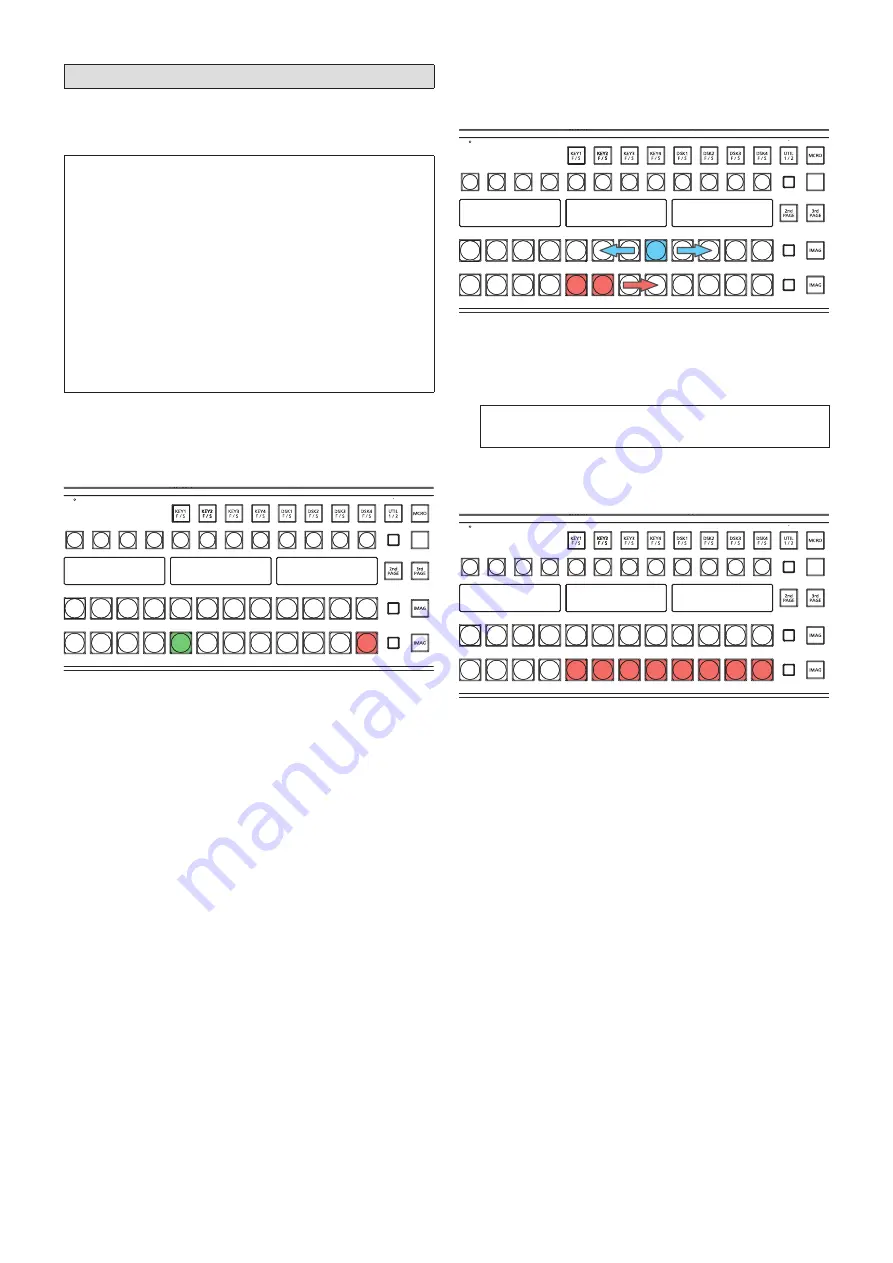
About 20 seconds after turning on the power, the Control 

Panel will enter the following state.

BUS

SHFT

p

p

Two of the PST/B bus crosspoint buttons in the bottom 

ME row blink.  

One button blinks green while the other blinks red.

Press the button that is blinking red.

Version upgrade of the Control Panel starts, and the 

Control Panel enters the following state.

BUS

SHFT

p

p

Eight of the PGM/A bus crosspoint buttons in the bottom 

ME row light blue temporarily in sequence from side to 

side.

p

p

Eight of the PST/B bus crosspoint buttons in the bottom 

ME row light red in sequence from left to right.

Do not turn off the Main Frame or Control Panel 

during this time.

After about 2 minutes, version upgrade of the Control 

Panel is complete, and the Control Panel enters the 

following state.

BUS

SHFT

p

p

Eight of the PST/B bus crosspoint buttons in the bottom 

ME row blink red.

Turn off the Main Frame and Control Panel.

p

p

If your system includes only one connected Control 

Panel, proceed to the “5. Verify the software version” 

procedure.

p

p

If your system includes two or more connected Control 

Panels, repeat steps 1 to 3 for each Control Panel, 

and then proceed to the “5. Verify the software version” 

procedure.

Summary of Contents for AV-HS6000

Page 1: ...g settings will be initialized when upgrading from Ver 3 or earlier of the AV HS6000 software p p SYS button SYSTEM Network tab Network1 column setting p p SYS button SYSTEM Network tab Network2 column setting p p SYS button CTRL PANEL SubPanel1 tab Network column setting p p SYS button CTRL PANEL SubPanel2 tab Network column setting The above settings are not saved to project files Make a memo of...

Page 2: ...he memory card used in the 2 Save project files procedure 3 Eject the memory card from the computer and insert it into the memory card slot on the AV HS6000 4 Press the SYS button on the left side of the Menu Panel to light it and select the MAINTENANCE Status tab in the menu screen 5 Select Update File in the Update column Select the version upgrade file in the file selection screen 6 Select OK t...

Page 3: ...S SHFT p p Two of the PST B bus crosspoint buttons in the bottom ME row blink One button blinks green while the other blinks red 2 Press the button that is blinking red Version upgrade of the Control Panel starts and the Control Panel enters the following state BUS SHFT p p Eight of the PGM A bus crosspoint buttons in the bottom ME row light blue temporarily in sequence from side to side p p Eight...

Page 4: ...pgrade was performed 1 Insert the memory card on which the project file is saved into the memory card slot on the AV HS6000 2 Press the PRJ button on the left side of the Menu Panel to light it and select the PROJECT SD SSD tab in the menu screen 3 Select LOAD in the SD column The LOAD screen appears Select the project file to load 4 Select OK The project file is loaded from the memory card p p Do...

Page 5: ...000 software again in Ver 3 of the software and register the macro register memory again Macro data operations that are not compatible between Ver 2 and Ver 3 Menu operations Top menu Function menu Menu tab Column Item ME1 ME2 KEY1 KEY2 KEY3 KEY4 Chroma Auto Compute Auto Compute Reset Sample Undo Sample Area Sampling MEM STILL Still Rec1 Rec Register Register SD Recall Store Misc SD Create Thumbna...

Reviews: