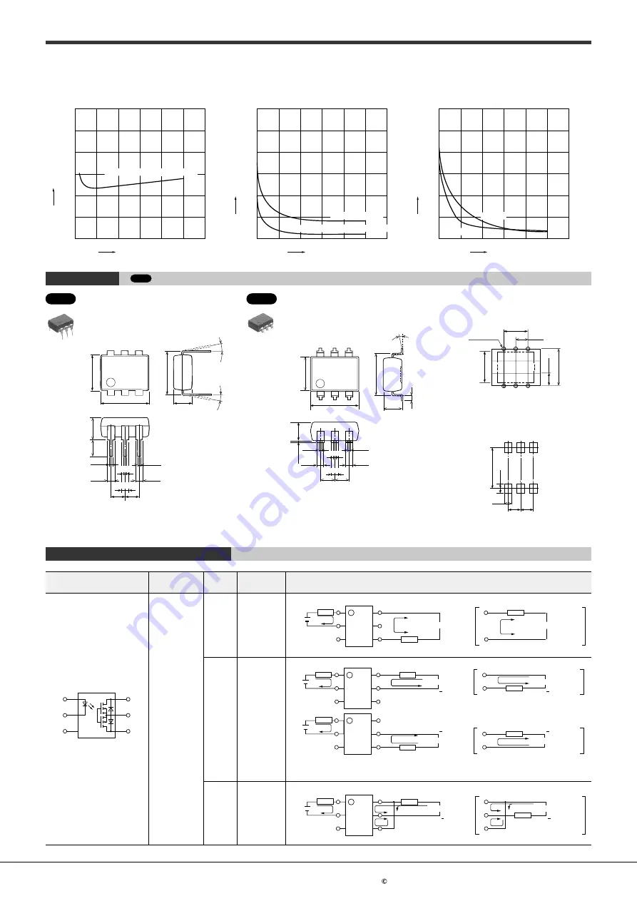
PhotoMOS HE HE 1 Form A
Panasonic Corporation Electromechanical Control Business Division
industrial.panasonic.com/ac/e/
ASCTB143E 202201
Panasonic Corporation 2022
7.
62
±
0.
05
±
0.
05
6.
4
±
0.05
8.8
3.4
±
0.
2
3.
9
0.47
0.47
1.25
2.54 2.54
1.25
3
1.25
0.47
Max.10
°
Max.10
°
Terminal thickness: t = 0.25
General tolerance: ±0.1
8.8
±
0.05
6.
4
±
0.
05
7.
6
3.4
1
3.4
0.47
0.47
0.47
1.25
1.25
1.25
2.54 2.54
0.
2
+0
.2
ー
0
Max.10
°
Terminal thickness: t = 0.25
General tolerance: ±0.1
5.08
2.54
6-0.8 dia.
2.
54
7.
62
6.
4
Tolerance: ±0.1
8.
3
1.
9
1.5
2.542.54
Tolerance: ±0.1
11-2. Turn off time vs. LED forward current
characteristics
0
0
0.04
0.02
0.06
0.08
0.10
0.12
10
20
30
40
50
AQV253H, AQV254H, AQV256H
AQV253H, AQV254H, AQV256H
LED forward current (mA)
Turn off time (ms)
Measured portion: between terminals 4 and 6;
Load voltage: Max. (DC); Continuous load current:
Max. (DC); Ambient temperature: 25°C
12-1. Output capacitance vs. applied voltage
characteristics
0
0
300
200
100
400
500
600
10
20
30
40
50
60
AQV253
(
H
)
, AQV254
(
H
)
, AQV257
AQV253
(
H
)
, AQV254
(
H
)
, AQV257
AQV251, AQV252
AQV251, AQV252
Applied voltage (V)
Output capacitance (pF)
Measured portion: between terminals 4 and 6;
Frequency: 1 MHz;
Ambient temperature: 25°C
12-2. Output capacitance vs. applied voltage
characteristics
0
0
60
40
20
80
100
120
10
20
30
40
50
AQV256H
AQV256H
AQV259
AQV259
Applied voltage (V)
Output capacitance (pF)
Measured portion: between terminals 4 and 6;
Frequency: 1 MHz; Ambient temperature: 25°C
CAD
Through hole terminal type
External dimensions
DIMENSIONS
CAD
The CAD data of the products with a “CAD” mark can be downloaded from our Website.
Unit: mm
PC board pattern
(BOTTOM VIEW)
Recommended mounting pad
(TOP VIEW)
Surface mount terminal type
External dimensions
CAD
SCHEMATIC AND WIRING DIAGRAMS
Schematic
Output
configuration
Load
type
Connection
Wiring diagram
1
6
3
2
5
4
*
1 Form A
AC/DC
A
1
I
L
2
3
6
5
4
V
L
(AC, DC)
E
1
I
L
6
4
V
L
(AC, DC)
I
F
Load
Load
DC
B
I
F
1
I
L
2
3
6
+
5
4
V
L
(DC)
I
L
6
+
5
V
L
(DC)
E
1
+
1
I
F
I
L
2
3
6
5
4
I
L
5
+
4
V
L
(DC)
V
L
(DC)
E
1
Load
Load
Load
Load
Can be also connected as 2 Form A type. (However, the sum of the continuous load current
should not exceed the absolute maximum rating.)
DC
C
+
1
I
F
I
L
2
3
6
5
4
V
L
(DC)
E
1
+
I
L
6
5
4
V
L
(DC)
Load
Load
*Terminal 3 cannot be used, since it is in the internal circuit of the device.
ー 6 ー


