background image

109

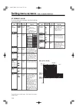
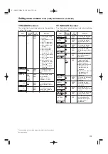
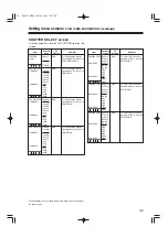
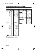
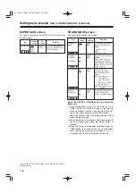
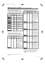
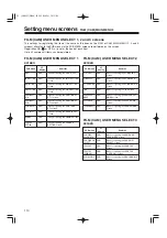
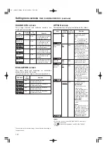
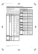
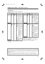
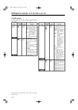
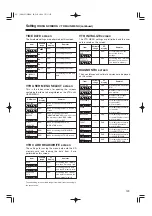
Setting menu screens  

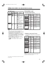
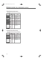
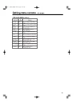
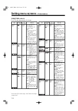
FILM (CAM) MAIN MENU 3 (continued)

The underlining in the variable range column indicates the setting in
the preset mode.

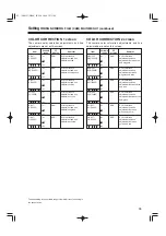
LENS ADJ screen

The lens adjustments are performed on this screen.

Item

Variable

range

Remarks

F2.8 ADJ

ON
OFF

VF

display

ENG

For outputting the voltage
output only when ON is
selected as this item’s
setting.

F16 ADJ

ON
OFF

ENG

For outputting the voltage
output only when ON is
selected as this item’s
setting.

<Note>

When using a lens which enables the open limit and close limit of
the lens aperture to be adjusted, set “F2.8ADJ” or “F16ADJ” to ON,
and repeatedly adjust so that the lens aperture will be set to “F2.8”
or “F16.”
(This adjustment need not be performed if the lens does not have
this adjustment function.)

 03. 英(P89-127) MENU  05.5.23  2:19 PM  ページ109

Summary of Contents for AJHDC27H - DVCPRO HD CAMERA

Page 1: ...Camera Recorder Operating Instructions VQT0R10 F0505T0 F Printed in Japan ENGLISH Before operating this product please read the instructions carefully and save this manual for future use 01 英 表1 25 05 5 18 10 38 ページ1 ...

Page 2: ...ith the instruction manual may cause harmful interference to radio communications Operation of this equipment in a residential area is likely to cause harmful interference in which case the user will be required to correct the interference at his own expense Warning To assure continued FCC emission limit compliance the user must use only shielded interface cables when connecting to external units ...

Page 3: ...ages 48 Switching the display mode 49 Setting the marker displays 49 Setting the camera ID 50 Screen displays 51 Remaining battery charge and audio channel level and remaining tape displays 51 Displays relating to errors and warnings 51 Displays relating to time codes 51 Adjusting the date and time 52 Adjustments and setup using the setting menus 52 Adjusting the white balance and black balance 53...

Page 4: ...NU 4 FILM CAM USER MENU SELECT 1 screen 110 FILM CAM USER MENU SELECT 2 screen 110 FILM CAM USER MENU SELECT 3 screen 110 BLACK SHADING screen 111 WHITE SHADING screen 111 FLARE screen 111 COLORIMETRY screen 111 INITIALIZE screen 111 DIAGNOSTIC screen 112 EVALUATION screen 112 OPTION screen 112 VTR MENUS VTR MAIN MENU screen 115 FUNCTION screen 116 BATTERY TAPE screen 117 BATTERY SETTING screen 11...

Page 5: ... have been achieved for the first time in a video camera The variable frame rate function can be set as desired from 4 fps frame sec to 60 fps The shutter speed can also be set from 0 8 of the frame rate aperture angle 3 degrees to 97 2 aperture angle 350 degrees enabling full use to be made of many different presentation techniques Along with continually recording at 60 fps the VTR unit enables s...

Page 6: ...ven format 4 piece filter disc sets available as standard accessories The filter best suited to the subject s brightness and color temperature can be selected Two independent sets of filter discs one for CC and one for ND each with four filter discs are provided as standard accessories Camera unit equipped to capture a wide range of image creation activities from cinema production to broadcasting ...

Page 7: ...s a Dolby B noise reduction circuit Audio functions OA phantom power supply type of microphone optional accessory with sharp directivity characteristics can be attached It can also be detached from the unit for use as an interview microphone OOther kinds of microphones can also be connected and using the model AJ MH800G microphone holder optional accessory attached to the unit NEWS REC function Th...

Page 8: ...er SHAN TM700 Extension control unit AJ EC3 Camera Recorder AJ HDC27H SD Secure Digital memory card Battery case AU M402H AC adapter AJ B75 Cassette tape AJ HP23LP AJ HP32LP Cleaning tape AJ CL12LP BP type battery Sony Battery case Battery mount connector accessory V mount adapter plate Sony Battery Anton Bauer Battery IDX Battery Sony Battery 2 0 inch viewfinder AJ HVF27BP 01 英 表1 25 05 5 18 10 3...

Page 9: ...y 3BREAKER button To protect the equipment the circuit breaker is tripped when an overcurrent flows inside the unit and the power is automatically turned off Push this button to the pushed in position after performing internal inspections and adjustments If there is no problem the power will be turned back on 4POWER switch ON Set here to turn on the power OFF Set here to turn off the power Parts a...

Page 10: ...s 2Light shoe Use this to attach the video light etc 3Lens mount Bayonet type Use this to attach the lens 4Lever for securing lens Insert the lens into the lens mount 3 and turn the lens mount ring using this lever to secure the lens 5Lens mount cap To remove the cap push the lever for securing the lens 4 up Keep the cap in place while the lens is not attached 6Lens cable microphone cable clamp Th...

Page 11: ... component which has been connected to the AUDIO IN CH1 CH2 connectors 5 is recorded 5AUDIO IN CH1 CH2 audio input channel 1 2 connectors XLR 3 pin An audio component or microphones are connected here 6LINE MIC 48V line input mic input mic input 48V selector switch This is used to switch the audio input signals from the audio component which has been connected to the AUDIO IN CH1 CH2 connectors 5 ...

Page 12: ...e flashing or lighting of the warning lamps and warning displays The sound heard from the speaker is automatically cut off when the earphone is connected to the PHONES jack MONITOR SELECT audio channel selector switch This is used to select the audio channels whose sound is to be output from the speaker or earphone CH1 The audio CH1 signals are output 1 2 The audio CH1 and CH2 mixed signals or ste...

Page 13: ...be seen in the viewfinder 2ZEBRA zebra pattern switch This is used to display the zebra pattern in the viewfinder ON The zebra pattern is displayed OFF The zebra pattern is not displayed When the unit is shipped the zebra pattern is set so that an area of less than 85 is displayed with a video level of at least 80 or so The required area of zebra pattern can be displayed by setting the ZEBRA 1 DET...

Page 14: ...ult setting the new setting will appear at the WHITE BAL switch display position on the viewfinder screen Example A Shooting recording playback function section 1 1CC FILTER ND FILTER filter selector control This is used to select the filter to match the light source which is illuminating the subject If the control setting is changed while the menu display mode is set to 3 default setting the new ...

Page 15: ... FILM CAM MAIN MENU 4 are set to ON and the AUTO W B BAL switch is pressed continuously for 8 seconds or more on the ABB side Parts and their functions continued OUTPUT AUTO KNEE switch setting position BARS Color bar signals are output Use this position in the following circumstances OWhen the video monitor is to be adjusted OWhen the color bar signals are to be recorded CAM AUTO KNEE OFF The pic...

Page 16: ...ON while performing the menu settings it is possible to superimpose the setting menus onto the pictures being shot so that they can be checked on the monitor screen The user bits are also output from the HD SDI MON connector The active frame count is output to the four higher digits of the user bits The count is reset to zero each time recording starts and the count is incremented with each active...

Page 17: ...ART button When this is pressed recording starts when it is pressed again recording stops This button functions in the same way as the lens VTR button VTR SAVE STBY tape protection switch This is used to switch the VTR operation status while the REC PAUSE mode is established for the VTR recording SAVE This is the tape protection mode The cylinder is stopped in the half loading status Less power is...

Page 18: ...on While this button is held down the camera s setting mode is shown in the viewfinder This does not affect the output signals of the camera USER 1 and USER 2 buttons A user setting can be allocated to each of these buttons using the setting menu When a button is pressed the user setting mode allocated to it is selected When the button is pressed again the selected mode is released AEJECT button T...

Page 19: ...p is operational OFF The unit s back tally lamp is not operational 3WARNING lamp When a problem of some form or other occurs within the VTR unit this lamp flashes or lights 4LIGHT switch ON The display window 5 is illuminated OFF The illumination of the display window is turned off 5Display window This displays the alarms remaining battery charge audio levels time data etc relating to the VTR unit...

Page 20: ...uration can be changed to suit the desired objective For details on the menu operation method refer to Menu operations on pages 86 to 88 Parts and their functions continued When the power is turned on Status display Camera unit s user menu VTR unit s user menu Press the MENU button Press the MENU button Press the MENU button Time code related section 1 1GENLOCK IN connector BNC Supply the analog H...

Page 21: ... the screen at the moment when this button is pressed is held However the time code generator keeps running When the button is pressed again the hold status is released It is used for instance to find out the time at which a particular scene was shot Note If the HOLD button is pressed and held down while the DISPLAY switch 6 has been set to UB HOLD on the counter display flashes and the button fun...

Page 22: ... the battery using the battery charger For details on the recharging method refer to the operating instructions of the battery concerned Note An intelligent battery system and ultra light system are supported 1Attach the battery pack Insert the pack in the direction shown by the arrows and then slide it into position 2To detach the battery pull the battery mount removal lever all the way down and ...

Page 23: ...screwdriver secure the battery case BP 90 type to the camera recorder Open the cover and lift the rubber cap so that the screw tightening hole is visible Tighten the screws to secure the battery case to the camera recorder Be sure to fully tighten the screws Notes ODo not use excess force when lifting the rubber caps forcibly OTake special care not to pinch the cable 4Set the battery type Select t...

Page 24: ...ry case to the unit 1Tighten the mounting screws 2Tighten the power contact screws 3Insert the top of the detached cover in the direction shown by the arrows 4Align the holes in the bottom of the cover metal part with the holes at the bottom of the case and use the screws to attach the case Note When mounting the battery case take care not to pinch the connecting cord 4Set the battery type Select ...

Page 25: ...and AC adapter have been connected OWhen using the AC adapter be absolutely sure to first set the power of the AC adapter to ON and then set the unit s power switch to ON If the power is turned on in the reverse sequence the output voltage of the AC adapter will rise gradually and the unit may malfunction as a result 1 2 3 4 1Connect the DC OUT connector on the AJ B75 AC adapter to the DC IN socke...

Page 26: ...into the cable clamp and connect it to the LENS socket Notes OFor details on handling the lens refer to the operating instructions which accompany the lens OThe following lens adjustments and camera adjustments may be necessary depending on the lens mounted 1 Lens flange back adjustment 2 Lens auto iris operating speed adjustment 3 Lens white shading adjustment performed on the unit Lever for secu...

Page 27: ...adjustment If the video level is too high use the filters and shutter 4Loosen the screw securing the F f flange focus ring Note On some lenses this may be marked as F b flange back ring 5Set the zoom ring to the telephoto position either manually or electrically 6Shoot the chart used for the flange back adjustment and turn the distance ring to adjust the focus 7Set the zoom ring to the wide angle ...

Page 28: ... dial button to move the arrow cursor to the ZEBRA1 DETECT item and press the JOG dial button 6Turn the JOG dial button select 70 and then press the JOG dial button to enter the setting n V F D I S P L A Y D I S P C O N D I T I O N N O R M A L D I S P M O D E 3 V F O U T Y V F D T L 4 Z E B R A 1 D E T E C T 0 8 0 Z E B R A 2 D E T E C T 0 8 5 Z E B R A 2 S P O T L O W L I G H T L V L 4 5 S Y N C ...

Page 29: ...ng the lighting position etc also when the lens aperture is not between F 4 and F 11 OAlways be sure to leave the electronic shutter at OFF Performing white shading adjustments 19Turn the JOG dial button to move the arrow cursor to YES and press the JOG dial button ACTIVE appears on the screen to indicate that automatic adjustment of white shading is being performed END appears on the screen upon ...

Page 30: ...h stored in one file in memory The white shading adjustment is now complete The adjusted values are retained in the non volatile memory so that there is no need to adjust the white shading again even after the unit s power is turned off When a multiple number of lenses are to be used refer to Writing the white shading adjustment values and flare adjustment values in the internal memory on the foll...

Page 31: ...OG dial button to select the file 1 to 8 to be recorded L E N S F I L E F I L E S E L E C T 1 R E A D W R I T E R E S E T A L L n T I T L E 1 5 2 6 3 7 4 8 7Press the JOG dial button again and turn it until the character to be set is displayed When the button is turned the character displayed is switched in the following sequence Space 7 letters A Z 7 numbers 0 9 7 symbols x 8Press the JOG dial bu...

Page 32: ...he JOG dial button to move the arrow cursor to the WRITE position 13When the JOG dial button is pressed the following message appears 14Turn the JOG dial button to move the arrow cursor to YES and press the JOG dial button The current white shading adjustment and flare adjustment values are now stored in the unit s internal memory Note The values will not be stored in the unit s internal memory if...

Page 33: ...to move the arrow cursor to the READ item L E N S F I L E F I L E S E L E C T 1 n R E A D W R I T E R E S E T A L L T I T L E 1 5 2 6 3 7 4 8 4Press the JOG dial button to enter the file number 1Perform the menu operations pages 86 to 88 and display the LENS FILE screen of FILM CAM MAIN MENU 3 2Turn the JOG dial button to move the arrow cursor to the FILE SELECT item 3Press the JOG dial button and...

Page 34: ...he left or right and adjust it to a position that allows easy viewing 3Tighten the viewfinder left right position anchoring ring Viewfinder stopper Viewfinder left right position anchoring ring Loosen the ring Tighten the ring Adjusting the viewfinder s front back position 1Loosen the viewfinder front back position anchoring ring 2Slide the viewfinder to the front or back and adjust it to a positi...

Page 35: ...attaching a microphone to the viewfinder optional accessory for use The microphone of the AJ MC700P mic kit optional accessory can be attached to the viewfinder AJ HVF27BP MIC IN jack Mic holder Locking screw 4Set the AUDIO IN switch or switches to FRONT in accordance with the audio channel or channels whose sound is to be recorded AUDIO IN switches 02 英 P26 88 05 5 18 10 42 ページ35 ...

Page 36: ...ching the AJ MH800G mic holder optional accessory When attaching a microphone to the main unit for use MIC IN jack AUDIO IN switches 2Attach the microphone holder AJ MH800G to the camera recorder using the the 2 screws included Screws provided with mic holder Locking screw 3Attach the microphone to the microphone holder and tighten the locking screw Locking lever 4Loosen the locking lever and adju...

Page 37: ...INE MIC 48V selector switch is set to 48V the phantom power supply system is supported When connecting a microphone to the MIC IN jack 1Connect the microphone s connecting cable to the AUDIO IN connector on the camera Two microphones can be connected to the CH1 and CH2 connectors 2Set the AUDIO IN switch or switches for the channel or channels to which the microphone or microphones have been conne...

Page 38: ... connectors on the camera with the audio component using the XLR cable 2Set the AUDIO IN switch or switches for the channel or channels to which the audio component has been connected to REAR When connecting audio components AUDIO IN connectors AUDIO IN switches LINE MIC 48V selector switch 02 英 P26 88 05 5 18 10 42 ページ38 ...

Page 39: ...nting the unit onto a tripod Pan head Tripod adapter Red lever Tripod adapter Detaching the unit from the tripod adapter While pressing the red lever move the black lever in the direction of the arrow slide the unit toward the rear and detach it Black lever Note If the pins in the tripod adapter fail to return to their original positions after the camera has been detached press the red lever again...

Page 40: ...e shoulder pad position 1Loosen the two screws 2Slide the shoulder pad either backward or forward and find the optimum position 3Tighten the screws to secure the shoulder pad The shoulder pad can be slid up to 15 mm either backward or forward from the center position factory setting Adjust the pad s position to operate the unit with the optimum ease Shoulder pad Screws Bottom section 2 1 3 Note Th...

Page 41: ...TA SAVE setting on the CAMERA SW MODE screen of FILM CAM MAIN MENU 2 all the adjustments and settings made using the AJ EC3 will be cleared when the unit s power switch is set to OFF When the unit is connected to the AJ EC3 again the KNEE POINT KNEE SLOPE GAMMA MASTER PEDESTAL and DETAIL items are returned to the AJ EC3 settings OWhen ON has been selected as the ECU DATA SAVE setting on the CAMERA...

Page 42: ...mp This lights when the unit is set to an abnormal operating status for any of the items set to ON on the LED screen of the setting menu For details on selecting the items targeted for the lamp display refer to the section on Setting the lamp displays next page 4VTR SAVE VTR power saving lamp This lights when the VTR SAVE STBY switch is set to SAVE It goes off during recording Note In the rec paus...

Page 43: ... menu operations pages 86 to 88 to open the LED screen 2Turn the JOG dial button to move the arrow cursor to the desired item 4Repeat steps 2 and 3 to set ON or OFF for the other items 3For the selected item press the JOG dial button and set whether or not the item is to be displayed on the viewfinder screen Turn the JOG dial button select display ON or no display OFF and press the JOG dial button...

Page 44: ...d 1 Extender display 2 Shutter speed mode display 3 Remaining tape display 4 Battery voltage display 5 Filter display 6 White balance memory display 7 Gain display 8 Audio level display 9 Aperture display Camera warning information display Safety zone markers Center marker Super iris ON display Zoom position display TCG display Master gain setting display A Color temperature display PRE A B B Batt...

Page 45: ...ing the GAIN switch 8Audio level display This indicates the audio level which can be displayed separately for audio CH1 and CH2 During sine wave input it roughly corresponds with the VTR s level meter as shown below 9Aperture display This indicates the approximate aperture setting F number Note This appears when a lens with an aperture display function is being used Camera warning information disp...

Page 46: ...F FILM or V VIDEO which has been set LCompression mode display This indicates COMP when DARK has been selected as the setting for the COMPRESSION MODE item which in turn is set from FUNCTION on the VTR MAIN MENU screen Selecting the display items The items to be displayed on the viewfinder screen can each be set to ON or OFF on the VF INDICATOR screen of the FILM CAM MAIN MENU 2 or on the VTR VF I...

Page 47: ... O N L E V E L M E T E R I N D C H 1 A U D I O I N I N D O F F T C I N D O F F V T R W A R N I N G I N D N O R M A L C O M P R E S S I O N I N D O N S A V E L E D S A V E On the VTR VF INDICATOR screen of VTR MENU ORemaining tape display TAPE ORemaining battery charge display BATTERY OLevel meter display LEVEL METER OAudio CH1 CH2 input display AUDIO IN OTime code display TC OVTR warning display V...

Page 48: ...n the gain setting has been changed GAIN n dB n 6 3 0 3 6 9 12 18 24 30 t t When the WHITE BAL switch setting has been changed WHITE n n ACH BCH PRESET t When the OUTPUT AUTO KNEE switch has been set to AUTO KNEE or OFF Note This display is shown for about 3 seconds immediately after the unit s power has been switched on AUTO KNEE ON or OFF t When the shutter speed mode setting has been changed SS...

Page 49: ...owing the unit s current statuses appear at the top and bottom of the viewfinder screen n V F D I S P L A Y D I S P C O N D I T I O N N O R M A L D I S P M O D E 3 V F O U T Y V F D T L 4 Z E B R A 1 D E T E C T 0 8 0 Z E B R A 2 D E T E C T 0 8 5 Z E B R A 2 S P O T L O W L I G H T L V L 4 5 S Y N C H R O S C A N D I S P d e g E C U M E N U D I S P O N Setting the marker displays The center marke...

Page 50: ...t position right and repeat steps 4 and 5 to set the characters 5Press the JOG dial button to enter the character 9Press the MENU button to exit the menu operations The setting menu is cleared and the displays showing the unit s current statuses appear at the top and bottom of the viewfinder screen n C A M E R A I D I D 1 2222222222 I D 2 2222222222 I D 3 2222222222 2Turn the JOG dial button to mo...

Page 51: ...rning displays RF Clogged video head SERVO Servo disturbance HUMID Formation of condensation on the head drum SLACK Problem in tape take up Displays relating to time codes Time code related switch settings and display items CH1 CH2 20 0 EMPHASIS 40 dB 10 30 E BATT F TAPE RF SERVO HUMID SLACK DF SLAVE TCG HOLD h min s frm Time counter display This displays the time code CTL user bits and actual tim...

Page 52: ...E SET and press the JOG dial button 5Press the MENU button to exit the menu operations The setting menu is cleared and the displays showing the unit s current statuses appear at the top and bottom of the viewfinder screen Note The seconds cannot be set The time always advances from 0 seconds n T I M E D A T E Y E A R 0 2 M O N T H 0 1 D A Y 0 1 H O U R 0 0 M I N U T E 0 0 T I M E D A T E S E T T I...

Page 53: ... results are appear on the viewfinder screen when the black balance or white balance adjustment is commenced Set the display mode to 1 if these messages are not to be displayed OFor details on the display mode settings refer to Display modes and setting change messages page 48 Notes OABB must be performed when the MASTER GAIN levels have been changed on the LOW SETTING MID SETTING and HIGH SETTING...

Page 54: ... one shown in the figure now appears The adjustment value is automatically saved in the memory A or B which was set in step 1 A W B A O K 3 2 K Message appearing upon completion of the adjustment 8A message such as the following appears if the color temperature of the subject is lower than 2300 K or higher than 5600 K The downward pointing arrow indicates that the color temperature is lower than t...

Page 55: ...e like this adjust AWB again Messages relating to white balance adjustment Error message Meaning Recommended action Select a suitable filter COLOR TEMP HIGH Color temperature is too high Select a suitable filter COLOR TEMP LOW Color temperature is too low Increase the amount of light or increase the gain LOW LIGHT There is not enough light Reduce the amount of light or reduce the gain LEVEL OVER T...

Page 56: ...everal seconds A message similar to the one shown in the figure now appears The adjustment value is automatically saved in the memory A B B O K Message appearing upon completion of the adjustment Notes OWhen using a lens with an auto aperture check that the lens connector has been connected OWhen using a lens with an auto aperture the aperture will be automatically set to where the light is blocke...

Page 57: ... 180 0 172 8 144 0 120 0 90 0 and 45 0 deg 1Perform the menu operations pages 86 to 88 and display the SHUTTER SELECT screen 4Press the MENU button to exit the menu operations The setting menu is cleared and the displays showing the unit s current statuses appear at the top and bottom of the viewfinder screen 2Turn the JOG dial button to move the arrow cursor to the desired item 3Press the JOG dia...

Page 58: ...C H R O S C A N 1 O N S Y N C H R O S C A N 2 O F F P O S I T I O N 1 O N P O S I T I O N 2 O N P O S I T I O N 3 O N P O S I T I O N 4 O N P O S I T I O N 5 O N P O S I T I O N 6 O N POSITION1 POSITION2 SYNCHRO SCAN 1 SYNCHRO SCAN 2 POSITION3 POSITION4 POSITION5 POSITION6 Setting the shutter mode and speed 1Following the steps for Switching the display mode page 49 set DISP MODE to 2 or 3 on the ...

Page 59: ...current statuses appear at the top and bottom of the viewfinder screen n V F D I S P L A Y D I S P C O N D I T I O N N O R M A L D I S P M O D E 3 V F O U T Y V F D T L 4 Z E B R A 1 D E T E C T 0 7 0 Z E B R A 2 D E T E C T 0 8 5 Z E B R A 2 S P O T L O W L I G H T L V L 4 5 S Y N C H R O S C A N D I S P d e g E C U M E N U D I S P O N V F D I S P L A Y D I S P C O N D I T I O N N O R M A L D I S...

Page 60: ...o images The images are processed using the video use cine gamma characteristics developed by Panasonic Switching the frame frequency This unit allows the frame frequency to be switched to 60 00 Hz or 59 94 Hz to provide support in areas with different video systems The frame frequency can be switched on the OPTION screen of FILM CAM MAIN MENU 4 1Perform the menu operations pages 86 to 88 and open...

Page 61: ...ILM CAM MAIN MENU 2 2Turn the JOG dial button to move the arrow cursor to the FRAME RATE item 3Press the JOG dial button and set the desired frame rate Turn the JOG dial button to select the frame rate and press the JOG dial button to enter the selection 4Press the MENU button to exit the menu operations The setting menu is cleared and the displays showing the unit s current statuses appear at the...

Page 62: ...r to the USER SW FRAME RATE item 4Turn the JOG dial button to move the arrow cursor to the FRAME MODE screen title and then press the JOG dial button 3Press the JOG dial button for setting the frame rate Turn the JOG dial button to select a frame rate 12 fps to 60 fps and then press the JOG dial button to enter the setting 7Turn the JOG dial button until F RATE is displayed and then press the JOG ...

Page 63: ...hite balance flare compensation auto knee and auto iris possibly giving the user the impression that something is odd or wrong The response time for automatic processes is particularly slow at a frame rate of 20 fps and below When the frame rate has been set to 20 fps or below it is recommended that the unit be operated with the automatic processing released 3Disturbed images The images may be dis...

Page 64: ...reverse Using an HD lens adapter made by Angenieux this unit supports the ultra prime lenses used for film cameras as a standard feature Furthermore it can also select the setting of the scan reverse function for canceling the image correction reversal of the top bottom and left right of the images that is performed when this adapter is used Setting the scan reverse 1Perform the menu operations pa...

Page 65: ...conds of the TIME DATE screen are adhered to OThe user bits setting contents are output to the six higher digits of the user bits in the VIDEO AUX area which used to be the VITC area In the internal color bar signal recording mode they are also output to the six higher digits of the LTC user bits OThe user bits cannot be set since the active frame information and other tape management information ...

Page 66: ...ery is replaced and the time code generator continues to operate for a prolonged duration approx 1 year Note When the POWER switch is set to ON 5 OFF 5 ON the backup accuracy of the time code is approximately 2 frames 1 4 2 5 Notes OWhen the frame rate is set to 24 fps this unit will perform the processing in the non drop frame mode in order to maintain the continuity of the frames even when the t...

Page 67: ...o guarantees can be made for the continuity of the external locking of the time code Gen locking of the camera unit while the time code is externally locked While the time code is externally locked the camera unit is gen locked by the reference video signal which is supplied to the GEN LOCK IN connector Notes OWhen the frame rate is set to 24 fps this unit will perform the processing in the non dr...

Page 68: ... the frame rate has been set to 24 fps and recording has been performed for 10 seconds 0240 will be displayed as the count When recording is started the count is reset to 0000 and the number of recorded frames per cut is counted up to 9999 Frame rate information 24 fps 23 98 fps Frame frequency 5 59 94 Hz 6 60 00 Hz Tape management information OActive frame information OREC START STOP mark VITC us...

Page 69: ...he arrow cursor to the READ USER DATA item 4Turn the JOG dial button to move the arrow cursor to YES and press the JOG dial button The data settings saved in the user area of the camera s memory are loaded and the settings are completed 5Press the MENU button twice The setting menu is cleared and the displays showing the unit s current statuses appear at the top and bottom of the viewfinder screen...

Page 70: ...le number starts flashing Turn the JOG dial button to select the scene file in which data is to be saved 4Press the JOG dial button to enter the scene file 5Turn the JOG dial button to move the arrow cursor to the TITLE1 TITLE2 TITLE3 or TITLE4 item that corresponds to the scene file whose title is to be provided I N I T I A L I Z E R E A D F A C T O R Y D A T A W R I T E U S E R D A T A S C E N E...

Page 71: ...R E A D U S E R D A T A T I T L E W R I T E Y E S n N O I N I T I A L I Z E R E A D F A C T O R Y D A T A W R I T E U S E R D A T A S C E N E S E L 1 R E A D n W R I T E R E S E T T I T L E 1 22222222 T I T L E 2 T I T L E 3 T I T L E 4 12Turn the JOG dial button to move the arrow cursor to the WRITE item I N I T I A L I Z E R E A D F A C T O R Y D A T A W R I T E U S E R D A T A S C E N E S E L 1...

Page 72: ...reen of FILM CAM MAIN MENU 4 2Turn the JOG dial button to move the arrow cursor to the SCENE SEL item n I N I T I A L I Z E R E A D F A C T O R Y D A T A W R I T E U S E R D A T A S C E N E S E L 1 R E A D W R I T E R E S E T T I T L E 1 T I T L E 2 T I T L E 3 T I T L E 4 I N I T I A L I Z E R E A D F A C T O R Y D A T A W R I T E U S E R D A T A n S C E N E S E L 1 R E A D W R I T E R E S E T T ...

Page 73: ... to be reset 4Press the JOG dial button to enter the scene file I N I T I A L I Z E R E A D F A C T O R Y D A T A W R I T E U S E R D A T A S C E N E S E L 2 R E A D W R I T E n R E S E T T I T L E 1 T I T L E 2 T I T L E 3 T I T L E 4 5Turn the JOG dial button to move the arrow cursor to the RESET item 7Turn the JOG dial button to move the arrow cursor to YES and press the JOG dial button The dat...

Page 74: ...connector on the edge of the SD memory card directly How to insert the SD memory card With the surface bearing the logo facing you insert the SD memory card into the SD memory card slot and close the cover Note Check that the surface bearing the logo is facing you and the lettering is not upside down before inserting the card When inserting the card check the direction in which the card is pointin...

Page 75: ...wing message appears Note When the card is formatted the settings statuses applying at the time are also saved in the memory 3When the JOG dial button is pressed the following message appears on the screen C A M C A R D R E A D W R I T E R E A D S E L E C T 1 W R I T E S E L E C T 1 C A R D C O N F I G R E A D U S E R D A T A T I T L E C O N F I G O K n C A M C A R D R E A D W R I T E S E L E C T ...

Page 76: ...l button to select a number from 1 to 8 and press the JOG dial button 5When the JOG dial button is pressed the arrow cursor moves to the title input area and the input mode is established 6Press the JOG dial button again and turn it until the character to be set is displayed When the button is turned the character displayed is switched in the following sequence Space 7 letters A Z 7 numbers 0 9 7 ...

Page 77: ...O K Y E S n N O T I T L E 22222222 12When the JOG dial button is pressed the following message appears C A M C A R D R E A D W R I T E R E A D S E L E C T 1 W R I T E S E L E C T 1 C A R D C O N F I G R E A D U S E R D A T A T I T L E W R I T E Y E S n N O T I T L E 22222222 Saving the data settings to the selected file SD memory card operations continued 10When the JOG dial button is pressed the ...

Page 78: ...s avove READ and press the JOG dial button 3Turn the JOG dial button to select any number from 1 to 8 and press the JOG dial button 4Turn the JOG dial button to move the arrow cursor to the READ item C A M C A R D R E A D W R I T E S E L E C T 1 n R E A D S E L E C T 1 W R I T E C A R D C O N F I G T I T L E R E A D R E A D U S E R D A T A T I T L E 1 5 2 6 3 7 4 8 5When the JOG dial button is pre...

Page 79: ... current statuses appear at the top and bottom of the viewfinder screen Error message Remedial action READ NG NO CARD SD memory card has not been inserted Insert the card READ NG FORMAT ERROR formatting error The card was formatted by a device other than the unit Replace the card READ NG NO FILE file not found Save the file data READ NG ERROR the data cannot be loaded Data saved by devices other t...

Page 80: ... OFF to turn off the unit s power Then turn the power back on and immediately hold down the EJECT button The cassette can be removed when there is still some power left in the battery However do not repeat this operation To prevent accidental erasure Set the cassette s tab to SAVE to prevent the recordings on the tape from being erased accidentally POWER ON HUMID display EJECT button Cassette hold...

Page 81: ...F RUN or R RUN OUTPUT CAM AUTO KNEE ON GAIN Normally set to 0 dB change to a more suitable value if the picture is too dark Aperture Automatic 2Set the POWER switch to ON Now check that the HUMID display is not showing and that at least 5 segments of the remaining battery charge display are lighted OIf the HUMID display is showing wait until it goes off OIf at least 5 segments of the remaining bat...

Page 82: ...e white balance 2 Press the AUTO W B BAL switch to the ABB position and adjust the black balance 3 Press the AUTO W B BAL switch to the AWB position and adjust the white balance again For details on how to adjust the white balance refer to Adjusting the white balance and black balance pages 53 to 56 2Point the camera at the subject and adjust the focus and zoom 3When the electronic shutter is to b...

Page 83: ...ress the VTR START button or lens VTR button to start the recording Proceed as follows either after the tape has been allowed to run or after the cassette has been ejected or when ensuring continuity on a tape which has been recorded only in part Ensuring scene to scene continuity at other times 1While monitoring the viewfinder screen press the PLAY PAUSE button to play back the tape 2At the place...

Page 84: ...ignal and adjusting the volume are accomplished using the MONITOR switch control page 12 Playback checking what has been recorded Depending on the internal VTR status the RET button functions which appear on the viewfinder screen change as follows Lens RET button functions Internal VTR status What appears on the viewfinder screen Pictures which are shot by the camera RET button does not work Durin...

Page 85: ...ing can be started from that point so that the no good cut will be deleted By cutting down on the time taken for copying onto the work tape for instance this function is very effective in achieving economical operation RETAKE function This function makes simple interval shooting intermittent recording possible It proves to be particularly effective when shooting programs with a nature theme or art...

Page 86: ...eparately Display method OWhen the MENU button is pressed the camera unit s USER menu screen is displayed OWhen the MENU button is pressed again the VTR unit s USER menu screen is displayed OWhen the MENU button is pressed once more the menu screen display is cleared Engineer menu All the setting menu items can be set on this menu The data settings are saved in the non volatile memory for long ter...

Page 87: ...t 3 seconds 2When the JOG dial button is pressed the next MAIN menu screen of the camera unit is displayed 3When the MENU button is pressed the VTR unit s MAIN MENU screen is displayed VTR USER MENU 5 5 FILM CAM MAIN MENU 1 FILM CAM MAIN MENU 2 FILM CAM MAIN MENU 3 FILM CAM MAIN MENU 4 Hold down the MENU button for at least 3 seconds Press the MENU button Press the JOG dial button Press the JOG di...

Page 88: ... O R R E C T I O N 2 L O W S E T T I N G M I D S E T T I N G H I G H S E T T I N G A D I T I O N A L D T L 1 A D I T I O N A L D T L 2 S K I N T O N E D T L K N E E L E V E L G A M M A C A M E R A S E T T I N G n R O P M A S T E R P E D 0 0 0 M A S T E R D T L 0 0 M A S T E R G A M M A 0 4 5 R G A I N 0 0 0 G G A I N 0 0 0 B G A I N 0 0 0 R P E D E S T A L 0 0 0 G P E D E S T A L 0 0 0 B P E D E S...

Page 89: ...L DTL CORING H DTL FREQ LEVEL DEPEND MASTER GAMMA BLACK STRETCH MATRIX TABLE COLOR CORRECT MASTER GAIN H DTL LEVEL V DTL LEVEL DTL CORING H DTL FREQ LEVEL DEPEND MASTER GAMMA BLACK STRETCH MATRIX TABLE COLOR CORRECT KNEE APERTURE SLIM DTL KNEE APE LVL DTL GAIN DTL GAIN DTL CLIP DTL SOURCE V DTL FREQ SKIN TONE DTL KNEE LEVEL GAMMA CAMERA SETTING SKIN TONE DTL SKIN TONE ZEBRA SKIN DTL CORING Y MAX Y...

Page 90: ... SHUTTER WHITE PRESET EXTENDER FILTER BLACK STR DAY LIGHT FILM MENU D5600K CAM MENU MATRIX COLOR CORRECTION FRAME RATE FILTER INH SHOCKLESS AWB COLOR BARS S GAIN OFF USER1 SW USER2 SW S BLK LVL ECU DATA SAVE AUTO KNEE SW FRAME MODE FRAME RATE RANGE FRAME RATE SCAN REVERSE S GAIN VALUE FILM CAM MAIN MENU 3 CAM CARD READ WRITE CAM CARD R W SELECT GENLOCK IRIS LENS ADJ SELECT READ SELECT WRITE CARD C...

Page 91: ...FILE LENS FILE CARD R W PLD FM EVF SEL SUPER DTL Item Variable range Remarks MASTER PED FILM MENU CAM MENU 200 000 018 200 Max VF display USER ENG MASTER PEDESTAL level setting How to interpret the menu lists The following abbreviations indicate whether the menu changes are stored written in the corresponding data or loaded read from the data The changes cannot be stored or loaded when is indicate...

Page 92: ...YSCON SERVO MECHACON FRONT YEAR MONTH DAY HOUR MINUTE TIME DATE SET VTR CARD READ WRITE READ WRITE READ USER DATA VTR INITIALIZE READ FACTORY DATA WRITE VTR USER DATA VTR USER MENU SELECT FUNCTION NEWS REC MODE HUMID OPE REC START PAUSE TIMER RETAKE MODE INTERVAL REC MODE INTERVAL REC TIME INTERVAL PAUSE TIME ECU REC CHK SW CHARACTER ON SDI BATTERY TAPE BATTERY SELECT EXT DC IN SELECT BATT NEAR EN...

Page 93: ...ening the VF INDICATOR screen CAMERA ID ENG Index for opening the CAMERA ID screen SHUTTER SPEED ENG Index for opening the SHUTTER SPEED screen SHUTTER SELECT ENG Index for opening the SHUTTER SELECT screen FILM CAM MAIN MENU 2 screen SUB menu VF display Remarks LED USER ENG Index for opening the LED screen CAMERA SW MODE USER ENG Index for opening the CAMERA SW MODE screen SUPER GAIN USER ENG Ind...

Page 94: ...L 100 000 100 Max USER ENG For setting B channel PEDESTAL level The underlining in the variable range column indicates the setting in the preset mode MATRIX screen The camera matrix is set on this screen Item Variable range Remarks MATRIX TABLE A B VF display ENG For selecting the color adjustment display MATRIX R G 31 00 31 ENG Color adjustment MATRIX R B 31 00 31 ENG Color adjustment MATRIX G R ...

Page 95: ...nts and hue adjustments are set on this screen Item Variable range Remarks R Mg SAT R Mg PHASE 63 00 63 VF display ENG Color saturation adjustment and hue adjustment between red and magenta Mg B SAT Mg B PHASE 63 00 63 ENG Color saturation adjustment and hue adjustment between magenta and blue B Cy SAT B Cy PHASE 63 00 63 ENG Color saturation adjustment and hue adjustment between blue and cyan Cy ...

Page 96: ...or correction matrix table COLOR CORRECT ON OFF USER ENG For setting the 12 axis independent color correction to ON or OFF The underlining in the variable range column indicates the setting in the preset mode MID SETTING screen The middle level gain is set on this screen Item Variable range Remarks MASTER GAIN FILM MENU 3dB 3dB 30dB VF display USER ENG 3 dB 0 dB 3 dB 6 dB 9 dB 12 dB 18 dB 24 dB or...

Page 97: ...NEE APERTURE ON OFF VF display USER ENG For setting the knee aperture to ON or OFF At the ON setting the detail above the knee point is boosted SLIM DTL ON OFF USER ENG For setting the mode to make the detail finer to ON or OFF ADDITIONAL DTL2 screen The special detail features of the camera are set on this screen Item Variable range Remarks KNEE APE LVL 0 5 VF display USER ENG For changing the de...

Page 98: ...s MASTER PED FILM MENU CAM MENU 200 000 018 200 VF display USER ENG For setting the master pedestal level MASTER PED MANUAL KNEE ON OFF USER ENG For setting the mode when the AUTO KNEE switch is at OFF KNEE POINT FILM MENU 30 65 90 USER ENG For setting the manual knee point position Note This setting is canceled when FILM REC has been selected as the CINE GAMMA SEL item setting on the GAMMA screen...

Page 99: ... SEL item setting OThe KNEE POINT and KNEE SLOPE item settings on the KNEE LEVEL screen are canceled Note The gamma characteristics are set using the BLACK STR LVL and DYNAMIC LVL items when FILM REC has been selected as the CINE GAMMA SEL item setting CAMERA SETTING screen The basic settings of the camera are set to ON or OFF on this screen Item Variable range Remarks DETAIL ON OFF VF display USE...

Page 100: ...ra pattern display Note When used at the SPOT setting ensure that the ZEBRA2 DETECT value is set higher than the ZEBRA1 DETECT value If the ZEBRA2 DETECT value is lower than the ZEBRA1 DETECT value the ZEBRA display will not appear The underlining in the variable range column indicates the setting in the preset mode Setting menu screens FILM CAM MAIN MENU 2 Change Display 1 2 3 t t FILTER t t GAIN...

Page 101: ...FF USER ENG For displaying the gamma curve used when the internal color bar signal recording mode is established The underlining in the variable range column indicates the setting in the preset mode Setting menu screens FILM CAM MAIN MENU 2 continued VF MARKER screen The information to be displayed inside the viewfinder is set on this screen Item Variable range Remarks SAFETY ZONE OFF 1 3 12 VF di...

Page 102: ... CAMERA ID screen The camera ID is set on this screen Item Variable range Remarks ID 1 2222222222 ID 2 2222222222 ID 3 2222222222 VF display ENG For inputting the camera ID max 10 characters Note Select whether this setting is to be mixed by selecting ON or OFF for CAMERA ID on the VF DISPLAY screen SHUTTER SPEED screen On this screen the shutter speed to be used is selected from among the POSITIO...

Page 103: ...00 1 2000 ENG For selecting the shutter speed which is to be set in POSITION 3 Item Variable range Remarks VF display POSITION 4 SEL FILM MENU CAM MENU 180 0 deg 172 8 deg 144 0 deg 120 0 deg 90 0 deg 45 0 deg 1 100 1 120 1 250 1 500 1 1000 1 2000 ENG For selecting the shutter speed which is to be set in POSITION 4 POSITION 5 SEL FILM MENU CAM MENU 180 0 deg 172 8 deg 144 0 deg 120 0 deg 90 0 deg ...

Page 104: ...range Remarks GAIN 0 dB ON OFF VF display USER ENG For setting whether the lamp is to be turned on when the gain level is other than 0 dB GAIN 3 dB ON OFF USER ENG For setting whether the lamp is to be turned on when the gain level is other than 3 dB SHUTTER ON OFF USER ENG For setting whether the lamp is to be turned on when the shutter is ON WHITE PRESET ON OFF USER ENG For setting whether the l...

Page 105: ... stored in the memory OFF The data is not stored in the memory AUTO KNEE SW FILM MENU CAM MENU ON OFF ON OFF USER ENG For setting whether the AUTO KNEE function is to be made operational when the OUTPUT AUTO KNEE switch on the side panel has been set to the CAM AUTO KNEE ON position ON The AUTO KNEE function is made operational OFF The AUTO KNEE function is not made operational USER1 SW FILM MENU ...

Page 106: ...R ENG This function is for correcting the images when the prime lens is used ON The images are corrected by reversing their top and bottom and their left and right OFF The images are not corrected S C U F E S C U F E S C U F E S C U F E S C U F E USER SW FRAME RATE 60 24 12 USER ENG For setting the frame rate to be allocated to the USER1 or USER2 button Using the USER1 or USER2 button to switch th...

Page 107: ...N OFF USER ENG For setting FILM CAM MAIN MENU 3 data saving loading when writing data onto the SD memory card or loading data from it to ON or OFF ON The data is recorded loaded OFF The data is not recorded loaded CAM MAIN MENU4 R W ON OFF USER ENG For setting FILM CAM MAIN MENU 4 data saving loading when writing data onto the SD memory card or loading data from it to ON or OFF ON The data is reco...

Page 108: ... is to be adjusted by the camera or lens IRIS GAIN VALUE 01 06 10 USER ENG For setting the iris gain adjustment value S C U F E S C U F E S C U F E S C U F E S C U F E S C U F E LENS FILE screen The lens files are stored into the unit s internal memory and read from the memory on this screen The white shading data and flare adjustment data are stored together as a lens file Item Variable range Rem...

Page 109: ...e output only when ON is selected as this item s setting F16 ADJ ON OFF ENG For outputting the voltage output only when ON is selected as this item s setting Note When using a lens which enables the open limit and close limit of the lens aperture to be adjusted set F2 8ADJ or F16ADJ to ON and repeatedly adjust so that the lens aperture will be set to F2 8 or F16 This adjustment need not be perform...

Page 110: ...reen KNEE LEVEL ENG Index for opening the KNEE LEVEL screen GAMMA ENG Index for opening the GAMMA screen CAMERA SETTING ENG Index for opening the CAMERA SETTING screen FILM CAM USER MENU SELECT 2 screen SUB menu VF display Remarks VF DISPLAY ENG Index for opening the VF DISPLAY screen VF MARKER ENG Index for opening the VF MARKER screen VF INDICATOR ENG Index for opening the VF INDICATOR screen LE...

Page 111: ...nge Remarks READ FACTORY DATA VF display ENG For restoring the film or camera menu data settings to the factory settings WRITE USER DATA ENG For saving the user s own film or camera menu data in the unit s memory SCENE SEL 1 4 ENG For designating the number of the scene file READ ENG For loading the scene file whose SCENE SEL was designated WRITE ENG For saving data in the scene file whose SCENE S...

Page 112: ...r menu display is selected on this screen Item Variable range Remarks ENG SECURITY ON OFF VF display ENG For selecting whether to display the engineer menu ON The engineer menu is not displayed OFF The engineer menu is displayed SHD ABB SW CTRL ON OFF ENG For selecting whether to automatically correct black shading when the AUTO W B BAL switch is pressed continuously for 8 seconds or more on the A...

Page 113: ... pedestal level OPTION screen Item Variable range Remarks EVF SEL MONO COLOR VF display ENG The EVF terminal video signal will be switched MONO Only the Y signal is output to the EVF connecter COLOR The Y Pb and Pr signals are output to the EVF connecter Currently there is no viewfinder to support this SUPER DTL ON OFF ENG For selecting the kind of detail to be provided ON A stronger detail than u...

Page 114: ... or OFF MATRIX ON OFF ENG For setting the MATRIX to ON or OFF FLARE ON OFF ENG For setting the FLARE to ON or OFF M PED FILM MENU CAM MENU 200 000 018 200 ENG For adjusting the master pedestal level OSensitivity measurement screen The sensitivity measurements are performed on this screen Item Variable range Remarks SENSITIVITY ON VF display ENG For setting the sensitivity measurement KNEE ON OFF E...

Page 115: ...en MIC AUDIO ENG Index for opening the MIC AUDIO screen TC UB ENG Index for opening the TC UB screen TIME DATE ENG Index for opening the TIME DATE screen VTR USER MENU SELECT ENG Index for opening the VTR USER MENU SELECT screen VTR CARD READ WRITE ENG Index for opening the VTR CARD READ WRITE screen VTR INITIALIZE ENG Index for opening the VTR INITIALIZE screen DIAGNOSTIC ENG Index for opening th...

Page 116: ...NE SHOT OFF USER ENG For selecting the intermittent recording mode ON Intermittent recording is performed ONE SHOT Intermittent recording is performed once and then stopped OFF Intermittent recording is not performed Note Intermittent recording is set OFF when the unit s power switch has been set to ON INTERVAL REC TIME 00s10f 59s29f USER ENG For setting the REC time for intermittent recording Not...

Page 117: ... 3 minutes 5min One segment is set to 5 minutes BATTERY TAPE screen Select the settings which match the type of battery used on this screen The warning tone which signals the remaining battery charge and remaining tape and which is heard during shooting can be switched off if they prove to be distracting Item Variable range Remarks BATTERY SELECT AJ BP490 AU BP402 PRO14 TRIM14 TRIM13 DIGITAL14 DIO...

Page 118: ...DX BP H90 battery BP H100 MANUAL AUTO ENG For setting the IDX BP H100 battery NP L50 MANUAL AUTO ENG For setting the IDX NP L50 battery ENDURA50 MANUAL AUTO ENG For setting the IDX ENDURA50 battery ENDURA D MANUAL AUTO ENG For use when mounting the V mount adapter plate made by IDX to use a digital battery BP L60 90 MANUAL AUTO ENG For setting the Sony BP L60 90 battery The underlining in the vari...

Page 119: ... input is displayed OFF The audio input is not displayed TC IND TCG TCR TCG TCR OFF USER ENG For selecting what the time code is to display TCG The time code generated by the time code generator is displayed in the E E mode TCR The time code reader value is displayed in the V V mode TCG TCR The time code generated by the time code generator is displayed in the E E mode the time code reader value i...

Page 120: ...y setting ON The embedded audio signals are output OFF The embedded audio signals are not output The underlining in the variable range column indicates the setting in the preset mode Note The frequency characteristics in the MIC LOWCUT ON mode are 200 Hz to 10 kHz MIC AUDIO screen Item Variable range Remarks VF display MIC LOWCUT CH1 FRONT REAR F R OFF USER ENG For setting the high pass filter for...

Page 121: ...ot stored when the power is turned off but is regenerated The underlining in the variable range column indicates the setting in the preset mode FIRST REC TC REGEN PRESET USER ENG For setting the TC REGEN mode when recording is started REGEN The time code set on the tape is regenerated However when the frame rate has been set to 24 fps the time code on the tape in those parts where the drop frame m...

Page 122: ... output as the user bits information in the VITC area TC DISP SEL 24F 25F 30F USER ENG For setting the number of frames to be displayed per second in the time code frame digits 24F 0 to 23 frames will be displayed per second 25F 0 to 24 frames will be displayed per second 30F 0 to 29 frames will be displayed per second Item Variable range Remarks VF display P OFF LCD DISPLAY ON OFF USER ENG For se...

Page 123: ...emarks READ VF display ENG For loading the VTR data from the SD memory card WRITE ENG For saving the VTR data onto the SD memory card READ USER DATA ENG For loading the VTR user area data contained in the unit s internal memory VTR INITIALIZE screen The VTR MENU settings are initialized and the user data is saved on this screen Item Variable range Remarks READ FACTORY DATA VF display ENG For retur...

Page 124: ...emarks VF display BATT NEAR END ALARM ENG For setting the registration of the BATT NEAR END ALARM item on the USER MENU screen BATT NEAR END CANCEL ENG For setting the registration of the BATT NEAR END CANCEL item on the USER MENU screen BATT END ALARM ENG For setting the registration of the BATT END ALARM item on the USER MENU screen BATT REMAIN FULL ENG For setting the registration of the BATT R...

Page 125: ...reen EMBEDDED AUDIO 60Hz ENG For setting the registration of the EMBEDDED AUDIO 60Hz item on the USER MENU screen A V SYNCHRO ENG For setting the registration of the A V SYNCHRO item on the USER MENU screen MIC AUDIO screen Item Variable range Remarks FRONT MIC POWER VF display ENG For setting the registration of the FRONT MIC POWER item on the USER MENU screen MIC LOWCUT CH1 ENG For setting the r...

Page 126: ...ion The warning points to a problem with the control signal inside the unit Consult your nearest service center RF LCD display The RF display flashes during recording WARNING lamp The lamp flashes four times a second during recording Tally lamp The lamp flashes four times a second during recording Warning alarm The alarm sounds four times a second during recording Viewfinder The RF display comes o...

Page 127: ...flashes BATTERY END LCD display WARNING lamp The lamp lights Tally lamp The lamp flashes once a second Warning alarm The alarm sounds continuously Viewfinder The BATT display lights What the warning indicates The battery is at the end of its charge VTR unit s operation All operation is stopped and the tape is unloaded Only cassette eject operation is possible Remedial action Replace the battery E ...

Page 128: ... the cassette to be removed Error codes One of the following error codes appears in the display window when an error has occurred in the unit for some reason 1Set the power to OFF 1 Set the power to OFF 2Remove the rubber cap where shown in the figure Insert a Phillips head screwdriver into the cross shaped part of the EMERGENCY screw red 3While pushing in with the screwdriver turn the EMERGENCY s...

Page 129: ...rket to wipe the lens ONEVER wipe the mirror If dirt or dust has found its way onto the mirror remove it using an air blower available on the market Cleaning inside the viewfinder Smear This phenomenon may occur when very bright subjects are shot The faster the electronic shutter speed the more likely that it will occur White blemish This phenomenon is caused by small white spots when dark places ...

Page 130: ...sushita part number VJS3824A004 Maker part number HR10A 7R 4SC Hirose Denki 1 2 3 4 ECU 1 CAM CONT RX 2 CAM DATA TX 3 NC 4 ECU ON 5 UNREG 12V 6 GND Matsushita part number K1AB106J0010 Maker part number HR10A 7R 6SC Hirose Denki 1 2 4 5 6 3 5 4 3 2 1 AUDIO OUT 1 GND 2 L CH OUT H 3 L CH OUT C 4 R CH OUT H 5 R CH OUT C Matsushita part number K1AA105H0007 Maker part number HA16RD 5P Hirose Denki Note ...

Page 131: ...20 UNREG GND Matsushita part number K1AB120H0001 Maker part number HR12 14RA 20SC 1 2 3 4 5 6 7 8 9 10 11 12 13 14 15 16 17 18 19 20 Note The maximum output current of the power supply is 1 0 A Note The maximum output current of the power supply is 1 0 A LENS 1 RET SW 2 VTR S S 3 UNREG GND 4 AT MA 5 ID CO 6 UNREG 12V 7 IP B 8 AT RE 9 EXT ANS 10 ZOOM POS 11 NC 12 NC Note Take care to ensure that th...

Page 132: ...ot come on and that at least 5 segments of the BATTERY display are lighted OIf the HUMID display has come on wait until it goes off OIf fewer than 5 segments of the BATTERY display have lighted replace the battery with one having an adequate charge 3After checking that there are no cables near the cassette holder or top panel press the EJECT button to open the cassette holder 4After checking the f...

Page 133: ... and set LEVEL METER on the VTR VF INDICATOR screen of VTR MENU to CH1 Check when sound is input from the microphone connected to the MIC IN jack on the lens that the audio level is displayed on the viewfinder screen Check when LEVEL METER on the VTR VF INDICATOR screen of VTR MENU is set to OFF that the audio level display is cleared from the viewfinder screen 9Check when the ZEBRA switch is set ...

Page 134: ...he tape is recorded played back and rewound properly 11Press the FF button and check that the tape is fast forwarded properly 2Set the zoom to the manual zoom mode and check its operations in this mode Turn the manual zoom lever and check that the image changes when the zoom is set to the telephoto and wide angle positions 3Set the aperture to the auto adjustment mode point the lens at some object...

Page 135: ...rce and check that the changes in the audio levels displayed on the audio level meter of the display window and in the viewfinder reflect the changes in the strength of the sound This inspection can also be performed for each channel by connecting one of the microphones to each channel in turn Inspections prior to shooting continued Inspecting the VTR unit 2 Automatic audio level adjustment functi...

Page 136: ...58 MHz 59 94 Hz 74 25 MHz 60 00 Hz Sampling frequency 74 1758 MHz 59 94 Hz 74 25 MHz 60 00 Hz Sensitivity F12 2000 lx 3200 K 89 9 reflection frame rate 23 98 fps synchro scan 50 Minimum subject brightness 0 7 lx with F 1 4 36 dB 89 9 reflection frame rate 59 94 fps Video S N ratio 54 dB typ Horizontal resolution More than 700 TV lines center Frame rate 3 996 fps to 59 94 fps 0 99 fps step 4 fps to...

Page 137: ...60 00 Hz synchronized with video Quantizing 16 bits Frequency response 20 Hz to 20 kHz 1 0 dB at reference level Dynamic range More than 85 dB at 1 kHz AWTD Distortion Less than 0 1 at 1 kHz reference level Wow and flutter Below measurable limits Head room 20 dB Input MIC IN XLR 3 pin female 40 dBu Phantom 48 V supported AUDIO IN CH1 CH2 XLRa2 3 pin female LINE MIC MIC 48V switching type LINE 4 dB...

Page 138: ...LATED COMPONENTS PARTS Relating to power supply Battery case AU M402H AC adapter AJ B75P Viewfinder 2 0 inch viewfinder AJ HVF27BP Relating to external VTRs Extension control unit AJ EC3P Audio components Microphone kit AJ MC700P Mic holder AJ MH800G Maintenance products Cleaning tape AJ CL12LP Soft carrying case AJ SC900 Hard carrying case AJ HT901G Rain cover SHAN RC700 Weight and dimensions ind...

Page 139: ...MEMO 04 英 P128 表4 140 05 5 18 10 45 ページ139 ...

Page 140: ...Marketing Department 52 West Gude Drive Rockville MD 20850 301 738 3840 Broadcast PARTS INFORMATION ORDERING 9 00 a m 5 00 p m EST 800 334 4881 24 Hr Fax 800 334 4880 Emergency after hour parts orders 800 334 4881 TECHNICAL SUPPORT Emergency 24 Hour Service 800 222 0741 Panasonic Canada Inc 5770 Ambler Drive Mississauga Ontario L4W 2T3 905 624 5010 Panasonic de Mexico S A de C V Av angel Urraza Nu...

Reviews: