background image


AJ8R


7


SPECIFICATIONS


1. Contact rating


Remark: The motor load is in accordance with EN61058-1. Inrush current can be switched up to the value of 6 times the indicated rating.

Voltage

Resistive load

(pf = 1)

Motor load

(EN61058-1)

(pf = 0.6)

Inrush load

125V AC

16A

160A (8.3ms)

125V AC

10A

4A


2. Coil rating


Remark: If the rated voltage is applied to the coil for more than ten seconds or the maximum voltage is applied for more than one second, coil perfor-

mance will deteriorate.

Nominal Voltage

*(Max. 10 sec)

Drop-out voltage

(at 20


°


68


°


 F

)

Nominal operating current

[


±


10%] (at 20


°


68


°


 F

)

Coil resistance

[


±


10%] (at 20


°


68


°


 F

)

Maximum voltage

(Max. 1 sec)

5V DC

Max.4.5V

Min.0.5V

725mA

6.9


5.5V

12V DC

Max.10.8V

Min.1.2V

300mA

40


13.2V

24V DC

Max.21.6V

Min.2.4V

150mA

160


26.4V


3. Characteristics


Remark: Test conditions are in accordance with EN61058-1,UL1054 and JIS C 6571

Electrical life

Manual operation

Min.10


4


(at 7 cpm.,at rated load)

Coil operation

Min.10


3


(at 7 cpm.,at rated load)
Min.5


×


10


4


(at 7 cpm. 5A 125V AC resistive load)

Mechanical life

Min.5


×


10


4


(at 20 cpm.)

Initial contact resistance
(By voltage drop at 1A, 2 to 4V DC)

Max. 100m


Initial insulation resistance

Min. 100m


 (at 500V DC measured by insulation resistive meter)

Initial breakdown voltage

Between contacts

2,000 Vrms

Between coil and contact

4,000 Vrms

Ambient temperature

0


°


C to +60


°


C

32


°


 F to +140


°


 F

(Not freezing below 0


°


32


°


 F

)

Ambient humidity

Max. 85% R.H.

Vibration resistance

10 to 55 Hz at single amplitude of 0.75mm

Shock resistance

Functional

Min.294m/s


2


{30G}

(Contact opening Max. 1ms)

Destructive

Min.980m/s


2


{100G}

Tensile terminal strength

.250 Quick-connect terminal Min. 98N{10kgf}/min.
(Pull & push direction)

Actuator strength

39.2N{4kgf} for 1min. operating direction

Contact release time

Max. 100ms (at rated voltage)

Initial operating force
* Reference value

4.9N or less (Max. 500gf or less)
Setting force after reset has been released: Max. 6.86N or less (Max. 700gf or less)

Flame retardancy

UL94V-0

Tracking resistance

Min. 175

Unit weight

Single pole, single throw: Approx. 17g 

.60oz

Single pole, double throw: Approx. 19g 

.67oz

Double pole, single throw: Approx. 20g 

.71oz

Summary of Contents for AJ8R

Page 1: ...h AMP s CT connectors which are widely used for wiring connections in OA equipment making it possible to achieve greater effi ciency in wiring work Receptacle for AMP s CT connector receptacle socket 4 Prolonged electrical service life Coil operation provides an electrical life of at least 50 000 switching operations 5 Assures excellent ability to with stand inrush current when used to turn a powe...

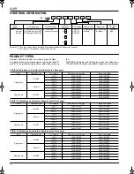
Page 2: ...tage Flange color Dark gray Flange color Black Single pole ON OFF 5V DC AJ8R1001ZC AJ8R1001ZBC 12V DC AJ8R1003ZC AJ8R1003ZBC 24V DC AJ8R1004ZC AJ8R1004ZBC ON ON 5V DC AJ8R5001ZC AJ8R5001ZBC 12V DC AJ8R5003ZC AJ8R5003ZBC 24V DC AJ8R5004ZC AJ8R5004ZBC Double pole ON OFF 5V DC AJ8R2001ZC AJ8R2001ZBC 12V DC AJ8R2003ZC AJ8R2003ZBC 24V DC AJ8R2004ZC AJ8R2004ZBC 3 With O indications on actuators Actuator...

Page 3: ... rated load Min 5 104 at 7 cpm 5A 125V AC resistive load Mechanical life Min 5 104 at 20 cpm Initial contact resistance By voltage drop at 1A 2 to 4V DC Max 100mΩ Initial insulation resistance Min 100mΩ at 500V DC measured by insulation resistive meter Initial breakdown voltage Between contacts 2 000 Vrms Between coil and contact 4 000 Vrms Ambient temperature 0 C to 60 C 32 F to 140 F Not freezin...

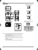
Page 4: ...terminals are 1 2 3 and 4 In the case of the single pole single throw ON OFF type the contact terminals are 1 and 2 In the case of the single pole double throw ON ON type the contact terminals are 1 2 and 4 There are no other terminals Refer to the internal wiring diagram 3 The coil is a polarized coil coil terminal 5 is positive and coil terminal 6 is negative Wiring diagram Bottom view Single po...

Page 5: ...t stress from the connecting wires 8 Take care not to drop the product as it may impair performance 9 Resistance to chemicals To clean the switch unit use a neutral detergent diluted with water Do not use acidic or alkaline solvents as they may damage the switch Furthermore be careful not to get any of the detergent solution inside of the switch while cleaning it 10 This product is not hermeticall...

Reviews: