background image

136

Manipulating Clips with Thumbnails: Setting the Thumbnail Display Mode

The thumbnail display mode can be customized to suit your 
preferences.

1

Press the THUMBNAIL button.
The thumbnail screen appears on the LCD monitor.

2

Press the THUMBNAIL MENU button and select 
THUMBNAIL 

 SETUP from the thumbnail menu.

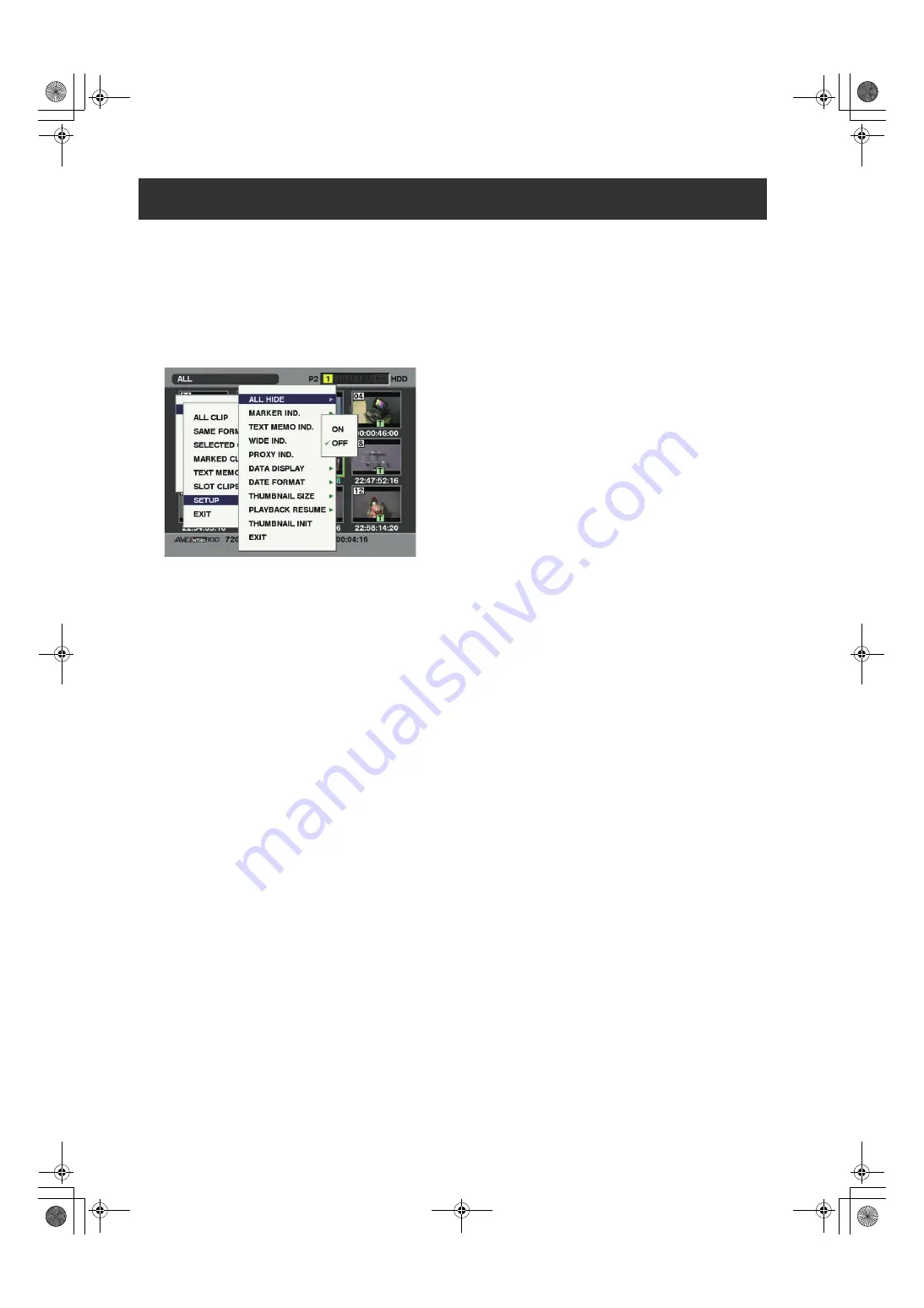
The following screen appears.

ALL HIDE:
ON:

All indicators are not displayed.

OFF:

Indication/No indication will be set depending 
on the following menu. The factory settings 
are as follows.

MARKER IND.:

Switches the shot mark marker between 
indication and no indication (ON/OFF). The 
factory setting is ON (indication).

TEXT MEMO IND.:

Switches the text memo marker between 
indication and no indication (ON/OFF). The 
factory setting is ON (indication).

WIDE IND.:

Switches the wide marker between indication 
and no indication (ON/OFF). The factory 
setting is ON (indication).

PROXY IND.:

Switches the proxy marker between indication 
and no indication (ON/OFF). The factory 
setting is ON (indication).

DATA DISPLAY:

The time display field of the clip offers a 
choice of Time Code (TC), User Bits (UB), 
Shooting Time (TIME), Shooting Date (DATE), 
Shooting Date and Time (DATE/TIME) or 
USER CLIP NAME. The factory setting is 
Time Code.

DATE FORMAT:

You can specify the display order for the 
shooting date as either Year/Month/Day (Y-M-
D), Month/Day/Year (M-D-Y) or Day/Month/
Year (D-M-Y).
The factory setting is Month/Day/Year.
This setting is reflected in the recording date 
shown in the clip property and the shooting 
date shown when DATE is selected under the 
item DATA DISPLAY.

THUMBNAIL SIZE:

For the size of thumbnails displayed on one 
screen, either LARGE (3 2 thumbnails 
displayed) or NORMAL (4 3 thumbnails 
displayed) can be selected. The factory 
default value is NORMAL.

PLAYBACK RESUME:

Selecting a position to restart playback after 
stopping playback on the thumbnails screen 
using the STOP button.

ON:

Playback starts from the stop position.

OFF:

Playback starts from the beginning of the clip 
indicated by the pointer.
Note that if the pointer is moved after stopping 
playback, the playback will restart from the 
beginning of the clip indicated by the pointer 
regardless of this setting. Also, attempting to 
playback from the end of all the available clips 
will cause the screen to flash momentarily, 
indicating that the there are no more clips 
which can be played back.

THUMBNAIL INIT:

Return the above thumbnail display settings to 
default. Move the cursor to this option, and 
press the SET button. Select YES when the 
confirmation screen is displayed.

EXIT:

Returns to the previous menu.

Setting the Thumbnail Display Mode

AJ-HPX2700G-VQT1V27_eng.book  136 ページ  2008年9月2日 火曜日 午後5時43分

Summary of Contents for AJ-P2C002SG

Page 1: ... is eligible for the P2HD 5 Year Warranty Repair Program For details see page 6 Before operating this product please read the instructions carefully and save this manual for future use F0808T0 F D Printed in Japan ENGLISH VQT1V27 AJ HPX2700G VQT1V27_eng book 1 ページ 2008年9月2日 火曜日 午後5時43分 ...

Page 2: ...nd 2 this device must accept any interference received including interference that may cause undesired operation FCC Note This equipment has been tested and found to comply with the limits for a class B digital device pursuant to Part 15 of the FCC Rules These limits are designed to provide reasonable protection against harmful interference in a residential installation This equipment generates us...

Page 3: ...tery for disposal at the end of its service life please consult your dealer PLEASE NOTE When preparing to record important images always shoot some advance test footage to verify that both pictures and sound are being recorded normally Should video or audio recording fail due to a malfunction of this camera recorder or the P2 cards used we will not assume liability for such failure If the unit is ...

Page 4: ...back Functions Section 18 Menu Operation Section 23 Time Code Section 24 Warning and Status Display Functions 25 Display Window Functions 26 LCD Monitor 27 Viewfinder 28 Recording and Playback P2 Cards 30 How to handle data recorded on P2 cards 32 Basic Procedures 33 Normal Recording 35 PRE RECORDING function 36 Variable Frame Rate VFR Recording Function 37 Loop Recording 40 Interval Recording 41 ...

Page 5: ...the Flange Back and White Shading Adjustments 111 Preparing for Audio Input 114 Mounting the Camera on a Tripod 115 Attaching the Shoulder Strap 116 Attaching the Rain Cover 116 Connection of the remote control unit AJ RC10G 117 Attaching the Front Audio Level Control Knob 118 Connection of the external switch 119 Manipulating Clips with Thumbnails Thumbnail Manipulations Overview 120 Thumbnail Sc...

Page 6: ...mber of hours the device has been used 1st year 2nd year 3rd year 4th year 5th year 5 P2HD device 2 Basic warranty 3 Extended warranty repair 4 Purchase P2 product Register online within 1 month Registration Notice e mail sent Details about user registration and the extended warranty http panasonic biz sav pass_e Free 5 years of Warranty Repairs Customers who register as users on the website will ...

Page 7: ...tained Supported formats For more details refer to Selecting a recording signal and method page 46 and Recording formats and output connector signal formats page 47 Attention Adjust the following 2 settings when using the unit for the first time Adjust the black balance setting when using the unit for the first time Refer to page 52 The unit is delivered from the factory with the color TV standard...

Page 8: ...ed into digital data by a 14 bit A D converter with sampling frequencies of 74 MHz It is possible to reproduce images that are more finely detailed DRS Dynamic Range Stretcher function With this function the dynamic range of high brightness areas that may be skipped with white blanks in an ordinary recording method can be expanded by compressing images and maintaining the contrast Refer to page 56...

Page 9: ... due to overwriting unless the files are deleted or the cards are initialized Recordings are written only to free space HD format AVC Intra100 AVC Intra50 DVCPRO HD switchable Recorded video is compressed through a component digital recording method that uses a state of the art compression technology and sound is recorded using the non compression PCM recording method which excels in such areas as...

Page 10: ...ogram which was registered on the SD memory card in advance This information is also useful in managing information on clips Regarding SD memory cards please also see Cautions in using SD memory cards page 22 Recording Time Operation of the following P2 cards with the unit has been verified AJ P2C004HG 4 GB AJ P2C008HG 8 GB AJ P2C016RG 16 GB AJ P2C032RG 32 GB The model numbers and capacities are a...

Page 11: ...By connecting the remote control unit AJ RC10G which is available as an optional accessory the unit can be controlled remotely Refer to page 117 Confirmation of return video signals It is possible to confirm the return video signals analog HD Y signals supplied to the GENLOCK IN connector of the unit in the viewfinder to confirm programs Only video signals from the same record format can be confir...

Page 12: ...12 General Dimensions drawing Unit mm inch Dimensions drawing 137 5 3 8 102 4 1 1 6 318 12 1 2 209 8 1 4 270 5 10 5 8 AJ HPX2700G VQT1V27_eng book 12 ページ 2008年9月2日 火曜日 午後5時43分 ...

Page 13: ...ain Notes The settings are not saved unless AREA SET is executed even if NTSC NTSC J or PAL is selected in the AREA SELECT When AREA SELECT is revised the AREA SET blinks When these items are set when the unit is used for the first time only the following 8 items are revised When the other settings of the unit are set in MAIN MENU the menu setting values for items other than the following 8 are on...

Page 14: ...ery case V mount type Battery plate NP L7 ENDURA7 10 BP GL65 95 Memory Card Camera Recorder AJ HPX2700G Tripod adapter SHAN TM700 Stereo microphone AJ MC900G Remote control cable AJ C10050G SD Memory cards P2 Cards AJ P2C016RG AJ P2C032RG Unislot wireless microphone receiver Sennheiser EK3041 Video encoder card AJ YAX800G Microphone holder AJ MH800G 2 type HD Viewfinder AJ HVF21G Lens Bayonet type...

Page 15: ... Lower this lever to lock the lens to the lens mount 10 Lens mount cap To remove the cap raise the 9 Lens lever When the lens is not mounted replace the cap 11 Light cable clamp Secures the light cable 12 Lens cable microphone cable clamp This clamp secures the lens and microphone cables 13 Tripod mount When you want to mount unit on a tripod the optional tripod adapter SHAN TM700 is attached here...

Page 16: ...nected to the 5 AUDIO IN CH1 CH2 connector is recorded Note When you use stereo microphone AJ MC900G optional set both CH1 and CH2 to FRONT The signal from L CH is recorded to CH1 and that from R CH to CH2 5 AUDIO IN CH1 CH2 audio input channel 1 2 connectors XLR 3 pin Audio devices or a microphone may be connected here 6 LINE MIC 48V line input mic input mic input 48 V selector switch Used to sel...

Page 17: ...o channel 2 or 4 is output You can select between stereo and mixed signal types using the menu option MONITOR SELECT This menu option can be found in the MIC AUDIO2 screen on the MAIN OPERATION page 12 MONITOR volume control Used to control the volume of sound output from the monitor speakers and earphones 13 ALARM warning alarm volume adjustment control Used to control the volume of the warning s...

Page 18: ...lance is automatically adjusted When the WHITE BAL switch on the side is positioned at A or B the adjusted value is stored in the memory Note that when the WHITE BAL switch is positioned at PRST this function does not work ABB Black balance is automatically adjusted Note To stop automatic adjustment of the white or black balance in progress set the switch to either AWB or ABB If automatic adjustme...

Page 19: ...Marker A to B Marker B and pressing again switches B to off no marker When the power is turned on the last selected indication before power down appears For more information see Marker Check Screen Displays MARKER SELECT button function page 85 Also with appropriate menu settings the MARKER SELECT button can be used as a USER 3 button For more information on user buttons refer to Assigning Functio...

Page 20: ...of the 15 HD SDI A B switch is output The video signal is the same as that output from the 29 HD SDI B connector 18 MON OUT monitor output connector The MON OUT connector is used for outputting video for the monitor The output signal can be switched between a down converted analog composite signal and an HD SDI signal This connector outputs video based on the setting of the 19 MON OUT SEL output s...

Page 21: ... lock button Used to open the slide out door for inserting P2 cards While depressing this button slide the door to the left 26 USB 2 0 connector DEVICE 27 USB 2 0 connector HOST A USB 2 0 cable is connected here When the menu option PC MODE is set to ON data can be transferred via USB 2 0 During such data transfer recording playback or operations of clips is limited The menu option PC MODE is foun...

Page 22: ...truction manual 33 SD memory card insertion slot An SD memory card optional is inserted here SD memory cards are used for recording and accessing the menu settings of cameras and the lens files uploading metadata and proxy recording optional Cautions in using SD memory cards Use the unit by inserting an SD memory card that is compliant with the SD standard or the SDHC standard MultiMediaCards cann...

Page 23: ...sertion slot An SD memory card optional is inserted here It is used when writing or saving menu data or lens files on an SD memory card 4 Busy operation mode display lamp This lamp indicates the active status of the SD memory card It stays illuminated when the card is active Note While the lamp is on do not insert or remove the card 5 SHOT MARKER MENU CANCEL button Undoes any changes to the menu o...

Page 24: ... display selector switch Indications of the time code CTL and user bits on the counter of the display window depend on the positions of this switch and the 7 TCG switch Pressing the 4 HOLD button also displays Date Time Time Zone UB User bits DATE TIME or Time zone indicated TC Time code indicated CTL CTL indicated 7 TCG time code selector switch This switch is used to specify the stepping mode fo...

Page 25: ... or stays on when a recordable P2 card is inserted 6 LIGHT button Use this button to control illumination of the display window Alternately pressing this button toggles illumination of the 7 Display window on or off 7 Display window This window displays warnings battery remaining level sound volume time data and other information Note When the battery is installed the unit indicates the data even ...

Page 26: ...HD OP SLOT CTL NDF d e f Mode indication HD Stays illuminated when the unit is in HD mode 1080i 720P GPS Stays illuminated when radio waves are not received during GPS operation GPS Stays illuminated when radio waves are received during GPS operation P REC Stays illuminated when the PRE REC MODE is set to ON and blinks when recording is continued after the recording tally lamp has gone out iREC Re...

Page 27: ...rding or playback 4 THUMBNAIL MENU button In thumbnail display mode this button allows you to manipulate the thumbnail menu e g to delete clips 5 Cursor and SET buttons The 4 triangular buttons are the cursor buttons and the center rectangular one is the SET button They are used to select a thumbnail and manipulate the thumbnail menu For more information see Manipulating Clips with Thumbnails page...

Page 28: ...mage in the viewfinder This does not affect the signal output from the camera 7 Front tally lamp This lamp is activated when the 3 TALLY switch is positioned at HIGH or LOW and stays on during recording It also blinks in synchronization with the REC lamp in the viewfinder and provides alerts Use the TALLY switch to change the intensity of the lamp to HIGH or LOW 8 Back tally lamp This lamp stays i...

Page 29: ...viewfinder Note For more information see the instruction manual for the viewfinder If when fitting a large lens there is insufficient space between the top of the lens and the bottom of the viewfinder the positions of the slide rails can be shifted upwards slightly by repositioning the screws a Conventional screw positions b Reposition and fix 3 screws here to raise the slide rail by approximately...

Page 30: ...ide out door 3 Insert a P2 card into the P2 card slot until the eject button pops up d Eject button e The card must be inserted with the logo right way up 4 Tilt up the popped up eject button f P2 card access LED 5 The P2 card access LED indicates the status of P2 card in the slot For how the P2 card status is indicated see P2 card access LED and status of P2 cards page 31 6 Close the slide out do...

Page 31: ...one when data are recorded on multiple cards spanning from one to the other hot swap recording For Your Information The P2 card access LEDs may be set to stay off using the menu option ACCESS LED This option can be found on the OPTION MODE screen on the SYSTEM SETTING page To prevent the content of a P2 card being accidentally erased position the write protect switch on the P2 card at Protect Note...

Page 32: ...eww pavc panasonic co jp pro av When using regular IT tools such as Microsoft Windows Explorer or Apple Finder to transfer data to a PC follow the instructions below However be sure to use the P2 Viewer when returning data to a P2 card Transfer the corresponding CONTENTS folder and LASTCLIP TXT file together as a set Do not transfer individual files from the CONTENTS folder When copying copy the L...

Page 33: ... Note When SLOT1 is selected for the menu option P ON REC SLOT SEL recording starts from the P2 card inserted in the smallest slot number after the power is turned on This option is found in the REC FUNCTION screen on the SYSTEM SETTING page When a battery and P2 cards are installed set the switches as detailed below before starting to use your unit Setting the switches before shooting and recordi...

Page 34: ...djust the black balance 3 Press the AUTO W B BAL switch toward AWB to adjust the white balance again For directions on making adjustments see Adjusting the White Balance page 49 and Adjusting the Black Balance page 52 3 Point the camera at your subject to adjust the focus and zoom 4 To use the electronic shutter set the shutter speed and operation mode For more information see Setting the Electron...

Page 35: ...ages and playback images is 59 94 or 50 frames that are pulled down Example of 1080 24PN Native Example of 720 24PN Native Notes The recording will start from the top frame of a 5 frame cycle for 24P 24PA recording a 4 frame cycle for 24P native recording or a 2 frame cycle for 30P and 25P native recording of 720P respectively Therefore the time code may be discontinued when recording clips contin...

Page 36: ...nd are recorded on the P2 card even if the PRE REC MODE menu option is set to OFF For details of the P REC display refer to 28 INTERVAL REC PRE RECORDING indication SD memory card remaining free space page 81 in Viewfinder Status Indication Layout Immediately after the power is turned on the menu option PRE REC TIME is selected and or the storage duration is changed the content in internal memory ...

Page 37: ...e code is fixed by the Rec run Thumbnail screens may be produced one frame later than in the video recorded to the P2 card It should be noted that this does not indicate a fault 1 Open the SYSTEM MODE screen from the SYSTEM SETTING page using the menu Set SYSTEM MODE to 720 59 94P 50P REC FORMAT to AVC I 100 60P and VFR to ON Set FRAME RATE suitable for desired way of shooting Any frame from 1 1P ...

Page 38: ...ion Use Standard Speed Shooting for Film Production Standard Settings for Film Production SYSTEM MODE setting Recording Frame Rate SYSTEM MODE Other settings 720 60P REC FORMAT AVC I 100 24PN AVC I 50 24PN DVCPROHD 24PN 24 frames VFR OFF FRAME RATE 24FRAME 1080 24PsF REC FORMAT AVC I 100 24PN AVC I 50 24PN CAMERA MODE 24P Standard Speed shooting for Commercial and TV production Standard settings f...

Page 39: ... quality When REC FORMAT is set to DVCPROHD 60P or DVCPROHD 50P the slow motion effect can be obtained by using a nonlinear editing system to process what has been recorded Undercrank Shooting Standard settings for undercrank shooting System frequency SYSTEM MODE setting Recording Frame Rate SYSTEM MODE Other settings 59 94 Hz 720 59 94P REC FORMAT AVC I 100 24PN AVC I 50 24PN DVCPROHD 24PN 1 23 f...

Page 40: ...y window When the menu option LOOP REC MODE is set to ON the space remaining on the P2 card is displayed as an estimated recording time for the current recording format When LOOP REC is stopped immediately after deleting an old recording the actual time remaining may be shorter than the displayed time When you set LOOP REC MODE to ON VFR is set to OFF During native VFR recording and use of the INT...

Page 41: ...EC TIME is set to 1 second 25 frames in the 25PN mode of 720P 1 Following basic operations of shooting and recording according to Basic Procedures lock the camera securely 2 Check that i is blinking in the display and that the interval recording mode is selected 3 Press either REC START STOP button or VTR button at the lens Interval recording starts Recording automatically stops after the specifie...

Page 42: ...e REC TIME option by pressing either the REC START STOP button or VTR button at the lens and returns to ONE SHOT pause mode 4 Press the STOP button The video and sound stored in memory are generated as one clip Press the RET button at the lens to put the unit into REC REVIEW mode ONE SHOT operation continues after the REC REVIEW Even during ONE SHOT mode clips will not be generated on the P2 card ...

Page 43: ... standby time is set to 1 minute or more or when in ONE SHOT mode the following restrictions apply even though the menu can be operated during stand by mode The respective settings of SYSTEM MODE REC FORMAT CAMERA MODE PC MODE and VFR cannot be changed The respective settings for SD CARD READ WRITE LENS FILE CARD R W READ USER DATA and READ FACTORY DATA cannot be executed When recording is paused ...

Page 44: ...case the viewfinder displays UPDATING If data is played back when the P2 card is being recognized the message CANNOT PLAY will be displayed If a P2 card is inserted while another P2 card is being played back the clips on the inserted P2 card will not be played back A P2 card inserted during playback will be recognized after playback ends If you perform variable speed playback on a clip split acros...

Page 45: ...le to add shot marks to incomplete clips refer page 122 For clips recorded on plural P2 cards or clips split on a P2 card refer to Notes on page 10 a shot mark is added to the top clip only The unit s recording mode works according to the priorities outlined in the following table relative to the setting of the menus and switches 1 Disabled for native recording 2 Disabled for native VFR recording ...

Page 46: ...lect the recording format AVC I 100 The AVC Intra100 format is used to record video The native recording format applies to the 30PN 24PN and 25PN modes AVC I 50 The AVC Intra50 format is used to record video The native recording is applied to the 30PN 24PN and 25PN modes DVCPROHD The DVCPRO HD format is used to record video The native recording is for the 30PN 24PN and 25PN modes Note When AVC I 5...

Page 47: ... 2 2 30 frames R RUN only DVCPROHD 24PN OFF Disabled 23 98P 23 98PN Native 24 frames 720 23 98P Over 59 94P 2 3 30 frames ON 1FRAME 60FRAME 1 59 94P 23 98PN Native 24 frames R RUN only For EE 720 P Over 59 94P Playback 720 23 98P Over 59 94P 2 3 30 frames R RUN only AVC I 100 60P AVC I 50 60P OFF Disabled 59 94P 30 frames 720 59 94P 30 frames No output ON 1FRAME 60FRAME 1 59 94P Over 59 94P 720 P ...

Page 48: ...Not shown 25P AVC I 100 50i AVC I 50 50i 50i AVC I 100 25PN AVC I 50 25PN 25P 720 59 94P DVCPROHD 60P Not shown OFF Disabled ON 1FRAME 60FRAME DVCPROHD 30PN OFF Disabled ON 1FRAME 60FRAME DVCPROHD 24PN OFF Disabled ON 1FRAME 60FRAME AVC I 100 60P AVC I 50 60P OFF Disabled ON 1FRAME 60FRAME AVC I 100 30PN AVC I 50 30PN OFF Disabled ON 1FRAME 60FRAME AVC I 100 24PN AVC I 50 24PN OFF Disabled ON 1FRA...

Page 49: ...iris 5 Flip up the AUTO W B BAL switch so that it is positioned at AWB then release it The switch returns to the central position with the white balance automatically adjusted Note To cancel automatic white balance adjustment in process the viewfinder displays AWB ACTIVE re position the AUTO W B BAL switch at AWB If automatic adjustment is canceled the value in effect before automatic adjustment w...

Page 50: ... each system stores only one value If this is the case the values are not synchronized with the filters This option can be found in the WHITE BALANCE MODE screen on the CAM OPERATION page When the menu option FILTER INH is set to OFF the adjusted value for each filter can be automatically stored in the memory that corresponds to the position of the WHITE BAL switch A or B Your unit has 4 built in ...

Page 51: ...TEMP A and COLOR TEMP B These options can be found in the WHITE BALANCE MODE screen on the CAM OPERATION page Note Even if the color temperature has been manually set automatic adjustment of the white balance AWB records the color temperature at the time of AWB at the position where the WHITE BAL switch was located When the CC filter position is switched the value for the color temperature changes...

Page 52: ...r screen may flicker and or display noise this is not a failure If you find the black shading annoying after performing an auto black balance adjustment adjust the black shading To do so go to the menu option DETECTION DIG move the cursor then press the jog dial button The menu option DETECTION DIG can be found in the BLACK SHADING screen on the MAINTENANCE page Note that pressing the ABB switch f...

Page 53: ... frame rate when using the VFR function For example when the VFR function is used with a frame rate frequency is 15 the variable range of the SYNCHRO SCAN is at 1 15 or more Setting the Electronic Shutter Shutter Modes To use the fixed shutter speed To use the shutter speed of SYNCHRO SCAN To use the half shutter speed HALF Video system Fixed shutter speed Half shutter speed Variable range for SYN...

Page 54: ... 1 Press the SHUTTER switch positioned at ON towards SEL a SHUTTER switch 2 Once more press the SHUTTER switch towards SEL Repeat this switchover until the desired mode or speed appears in the viewfinder screen If all modes and speeds are available the display changes in the following order See Viewfinder Screen Status Displays page 74 Note When recording using VFR set the shutter speed to 1 60 or...

Page 55: ...In SYNCHRO SCAN mode the shutter speed display can be switched between seconds and degrees For more details refer to SYNCHRO SCAN DISP page 179 In SYNCHRO SCAN2 mode the shutter speed can only be displayed in seconds When the frame rate is low pressing the SYNCHRO SCAN adjustment buttons to change the shutter speed only gives a small change in the time and consequently the shutter value in the vie...

Page 56: ...function is turned on off When the DRS function is turned on Gamma mode the Knee function and the BLACK GAMMA function are not available ASSIST The function to turn on or off of the focus assist indication is assigned Note When the ASSIST function is turned on a graph is displayed on the bottom right of the viewfinder and the LCD monitor Adjust the focus ring on the lens so that the graph comes fu...

Page 57: ...n is ON PC MODE The function to turn on or off the assigned USB device or USB host mode Switching between the USB device and USB host modes is set by selecting the PC MODE SELECT menu option in the SYSTEM MODE screen on the SYSTEM SETTING page TEXT MEMO Function of switching the text memo function on off is assigned For more details about the text memo function refer to Text Memo Function page 44 ...

Page 58: ...orded on audio channels 1 2 3 and 4 are selected with the AUDIO IN switch For more information see Audio input Function Section page 16 a Display window b MONITOR CH1 3 ST CH2 4 selector switch c MONITOR SELECT CH1 2 CH3 4 selector switch d AUDIO IN switch CH1 CH2 CH3 CH4 e AUDIO LEVEL CH1 CH2 controls f AUDIO SELECT CH1 CH2 switch Notes Four channel recorded audio signals are SDI output as they a...

Page 59: ...thout a sound recordist it is recommended that the FRONT AUDIO LEVEL control should be used to adjust the audio level Preset the channel to be adjusted and use the FRONT AUDIO LEVEL control to adjust the audio level while checking the audio level meter in the viewfinder to ensure that the level does not become excessive This function enables the recording level to be adjusted using the FRONT AUDIO...

Page 60: ...tively However in the following cases at least one of UB and VITC UB is always frame rate information in order to support editors PC software of the like which make use of information about the frame rate employed at shooting In 720P mode both the UB and VITC UB are always frame rate information For recording 24P 24PA in 1080i mode VITC UB is fixed to frame rate information In Native mode VITC UB ...

Page 61: ... 50 30PN 30P 30PN Native As per the UB MODE 4 6 Always frame rate information 5 AVC I 100 24PN AVC I 50 24PN 24P 24PN Native Always non drop frame 3 24 Recording 24 fixed Playback 30 24 switchable 1080 23 98PsF AVC I 100 24PN AVC I 50 24PN 24P 24PN Native Always non drop frame 3 24 HD SDI A B 24 Otherwise 30 Recording Playback 24 As per the UB MODE 4 Always frame rate information 5 1080 24PsF AVC ...

Page 62: ... 63 REGEN The user bits last recorded on the current target P2 card is read and recorded as is USER EXT VITC UB MODE only The included user s value is recorded as the user bits for the VIDEO AUX area It is the same value as the user bits indicated when the option UB MODE is set to USER or EXT a HOLD switch b DISPLAY switch c Display window d TCG switch e Cursor and SET buttons 1 Position the DISPL...

Page 63: ... d Frame rate e Camera shooting mode SYSTEM MODE REC FORMAT VFR CAMERA MODE At recording At playback 1080 59 94i DVCPROHD 60i AVC I 100 60i Not applicable 60i 0 0 DVCPROHD 60i 30P 8 8 24P 8 8 24PA C C AVC I 100 30PN 30P 8 8 AVC I 100 24PN 24P C 8 1080 23 98PsF AVC I 100 24PN 24P C 8 1080 24PsF AVC I 100 24PN 24P E A 1080 50i DVCPROHD 50i AVC I 100 50i 50i 2 2 25P A A AVC I 100 25PN 25P A A f Media...

Page 64: ...formation for the 6 digits to the right b Fixed value c Frame rate d Camera recording mode SYSTEM MODE REC FORMAT VFR CAMERA MODE At recording At playback 720 59 94P DVCPROHD 60P AVC I 100 60P OFF Not set 60P 8 8 ON 1 60FRAME 9 9 DVCPROHD 30PN AVC I 100 30PN OFF Not set 30P 8 8 ON 1 60FRAME 9 9 DVCPROHD 24PN AVC I 100 24PN OFF Not set 24P C 8 ON 1 60FRAME D 9 720 60P DVCPROHD 24PN AVC I 100 24PN O...

Page 65: ...at F RUN or R RUN this also activate the internal clock To cancel date time and time zone settings in process hold down the SET button and position the TCG switch at F RUN or R RUN Clock accuracy fluctuates between about 30 seconds per month when the power is turned off If more accurate timekeeping is required check the time when the power is turned on and if necessary reset the clock When the GPS...

Page 66: ...gned the SLOT SEL function the same time code is added to the last recorded clip on the target P2 card When no clips have been recorded recording starts from a value generated by a time code generator in the unit The menu option FIRST REC TC can be found in the TC UB screen on the MAIN OPERATION page If the menu option FIRST REC TC is set to PRESET if the time code has been set or reset or if the ...

Page 67: ...ooting timing may not correspond to each other Note that when the unit is in the 1080 23 98PsF or 1080 24PsF modes it is not possible to lock the time code using the VBS connection with one unit as a reference unit in the manner shown in Example 2 When using these modes connect the unit in the manner shown in Example 4 and Example 6 Externally Locking the Time Code Example of connections for exter...

Page 68: ... not necessary to supply a time code output signal to the VTR Example 4 When the unit and an external device are locked to the external time code generator and when several units of the camera are connected in a cascade configuration Setting of the TC VIDEO SYNCHRO item Item Variable range Remarks TC VIDEO SYNCHRO 0 1 2 3 For setting to correct the time code according to the delay of video signals...

Page 69: ...izes with the TC IN input and capable to record without delay DAT etc Settings of the TC VIDEO SYNCHRO item 3 TCG TC OUT TC OUT TC IN TC IN AJ HPX2700 TC OUT AJ HPX2700 GENLOCK IN GENLOCK IN GENLOCK IN TC IN TC OUT AJ HPX2700 TC IN DAT Reference video signal To be connected if necessary A device that synchronizes with the TC IN input and capable to record without delay such as DAT or a camera reco...

Page 70: ...de should be supplied When the TCG switch is positioned to F RUN only the time code is locked to an external time code To lock the user bits to an externally input value the UB MODE and VITC UB MODE menu options must be set to EXT and USER EXT respectively The menu option UB MODE and VITC UB MODE can be found in the TC UB screen on the MAIN OPERATION page Discontinue external time code supply then...

Page 71: ...racter turn the jog dial button to move the arrow cursor to the appropriate character and carry out steps 4 and 5 7 When all the characters are set turn the jog dial button to move the arrow cursor to 8 Pressing the jog dial button brings the arrow cursor back to the options ID1 ID3 9 To exit the menu press the MENU button Notes When the menu option CAMERA ID is set to BAR the camera ID is recorde...

Page 72: ...e user entry area allowing you to enter a user name 4 Turn the jog dial button until a desired character appears The characters appear in the following order Note The COUNTRY entry can only include alphabetical characters and spaces 5 Press the jog dial button to accept a desired character 6 Turn the jog dial button to move the arrow cursor to the next digit clockwise and repeat steps 4 to 5 to se...

Page 73: ...e first clip is used as a reference value for recalculation and the new playback CTL count is displayed The playback order of clips is altered when either of the following occurs Clips are deleted copied or restored or the P2 card is formatted The thumbnail display is switched for more information see Switching the Thumbnail Display page 124 A P2 card is inserted or removed The reference value val...

Page 74: ... flat The battery should be replaced before it is nearly flat so that operation will not be interrupted For more information see Warning System page 155 4 SAVE Lamp In the normal setting The lamp stays on when the SAVE switch is positioned at ON and the output of video and audio is power saved When the menu option SAVE LED is set to P2CARD The lamp starts blinking when the P2 card remaining free s...

Page 75: ...n or off the appropriate options or specify desired values For directions on setting the options see Setting Menu Options page 163 The indications are arranged as illustrated below For more information see the following pages Selecting Viewfinder Display Information Viewfinder Status Indication Layout 1 2 4 3 6 5 7 9 8 29 28 27 10 11 12 13 14 15 16 21 18 19 30 22 23 24 25 26 31 13 17 20 37 38 34 3...

Page 76: ...luminated when the P2 card is write protected LOOP LOOP is illuminated when the LOOP REC mode is set When loop recording cannot be performed for example because the P2 card has no free space the indication blinks INFO P2 P2 card being recognized Total free space capacities of the P2 cards when MODE CHECK is being performed Note When the menu option P2CARD REMAIN is set to ONE CARD the number of th...

Page 77: ...B CHAR HD SDI A B CHAR is set from the OUTPUT SEL screen of the SYSTEM SETTING page FUNCTION MON OUT OUTPUT MEM CAM OFF SELECT VBS HD SDI CHAR ON OFF Position of OUTPUT SEL switch Indicates current setting of MONITOR OUT MONITOR OUT is set from the OUTPUT SEL screen of the SYSTEM SETTING page Indicates current setting of MON OUT CHARACTER switch FUNCTION P2CARD STATUS TOTAL SLOT1 SLOT2 SLOT3 SLOT4...

Page 78: ...as been turned on or off Indicated when the iris override correction value is to be changed The dynamic range stretcher has been switched Low light warning LOW LIGHT Brightness too low Y GET value With the Y GET ON setting the output brightness level near the center marker is displayed as 12 User button functions INH I OVR ON OFF S BLK OFF B GAMMA ON OFF Y GET ON OFF DRS ON OFF ASSIST ON OFF C TEM...

Page 79: ...cation blinks USB HOST Indicates that the unit is set to the USB HOST mode When the external hard disk is not successfully recognized then the indication blinks THUMBNAIL OPEN Thumbnail is being manipulated 1394 INITIAL ERROR Displayed when the connection of the DVCPRO connector is abnormal PROXY REC P2 SD Displayed when proxy recording on either the P2 card or the SD memory card starts when AJ YA...

Page 80: ...o a proper position 19 Dynamic range stretcher mode DRS This is displayed when the function for compressing the video levels of sections with high brightness to stretch the dynamic range has been selected 20 WHITE BAL switch position A B P WHITE BAL switch positioned at A WHITE BAL switch positioned at B WHITE BAL switch positioned at PRST 21 42 Gamma Indication HD SD FLK1 FLK2 FLK3 FREC VREC This...

Page 81: ...ce on the SD Memory card will be displayed when the MODE CHECK button is pressed during proxy recording END END is displayed when there is no remaining free space 29 Compression mode COMP This appears when setting the mode for suppressing distortion of compressed video images that may occur when dark parts are shot Only for the DVCPRO HD at 720P 30 44 VF GAMMA This is only enabled when FILM REC ha...

Page 82: ...ach represents 1 3 STOP GAMMA MODE SEL is set from the GAMMA screen of the PAINT page STATUS MODE is set from the VF DISPLAY screen of the VF page P2 Card Remaining Free Space capacity Indication Status of unit Recording status Menu option P2CARD REMAIN 1 5 P2 card remaining free space indication 2 6 P2 card remaining free space indication during MODE CHECK 2 Under normal conditions Other than LOO...

Page 83: ...ining level voltage 10 MODE CHECK Indication Area 11 Camera Warning and Report Area 12 User button functions 13 System information and warnings 14 Time code indication 15 CAC 16 Extender 17 Color temperature 18 Filter position 19 Dynamic range stretcher mode 20 WHITE BAL switch position 21 Gamma Indication 22 Gain value 23 Audio input channel and level meter All 4ch input information 24 Super blac...

Page 84: ...o view TABLE B press the MARKER SELECT button This changes the indication to MRK B allowing you to view the settings Display Modes and Setting Changes adjustment Result Messages Setting change adjustment messages and DISP MODE settings Message appears when Message DISP MODE settings 1 2 3 CC filter ND filter changed ND n n 1 2 3 4 CC m m A B C D Gain changed GAIN n dB n 3 0 3 6 9 12 15 18 21 24 27...

Page 85: ...r marker c Safety zone d The view angle specified through the menu option FRAME SIG is displayed The viewfinder displays the return video signal input to the GENLOCK IN connector while the RET button at the lens is held down Note however that the return video signal cannot be viewed unless the signal format set using SYSTEM MODE matches the input signal to the GENLOCK IN connector To enable this c...

Page 86: ...moisture with a soft dry cloth When the unit is very cold the video image in the LCD monitor will appear slightly darker immediately after the power is turned on Once the interior of the unit warms up the LCD monitor delivers normal brightness When shooting with the LCD display angled 180 degrees towards the lens you can set the menu option SELF SHOOT to MIRROR to horizontally flip the video image...

Page 87: ...al is output from the HD SDI A B connector a HD SDI A B switch Selection of video output signals Settings of signals output from HD SDI A B connector Item Variable range Remarks OUTPUT ITEM MENU ONLY TC STATUS Set the characters to be superimposed on the output signals from the HD SDI A B connector and MON OUT connector MENU ONLY The menu screen is superimposed only when the menu is accessed This ...

Page 88: ...Set the characters to be superimposed on the signals output from the MON OUT connector in the OUTPUT ITEM item on the menu OUTPUT SEL screen on the SYSTEM SETTING page c MON OUT CHARACTER switch Note When VBS has been selected as the MON OUT signal and the menu option SYSTEM MODE has been set to 1080 24PsF and 720 60P the MON OUT signal is luminance signal video The menu option SYSTEM MODE can be ...

Page 89: ...from the SYSTEM MODE screen on the SYSTEM SETTING page Do not edit the data stored on the SD memory card using a PC or the like An SD memory card optional can be used as a setup card that stores up to 8 files of settings menu specifications This data allows you to quickly reproduce an optimum state Regarding SD memory cards please see Cautions in using SD memory cards page 22 Handling data Set dat...

Page 90: ... kept inserted into the unit with the lid closed To format an SD memory card write settings data or read data on an SD memory card navigate the menu to the SD CARD READ WRITE screen from the FILE page Insertion of an SD memory card formatted to a standard other than the SD and SDHC standards using some other device will result in the display of FORMAT ERROR on the top right part of the window In t...

Page 91: ...to the SD CARD READ WRITE screen 2 Turn the jog dial button to move the arrow cursor to the option W SELECT Then press the dial button 3 Turn the jog dial button to select a desired number 1 8 Then press the dial button 4 Turn the jog dial button to move the arrow cursor to the option TITLE 5 Press the jog dial button This moves the arrow cursor to the entry area putting the unit in entry mode Err...

Page 92: ... screen can be used to select the type of the menu to be written on the SD memory card It is possible to overwrite a setup file stored by a different device with a new setup file from this unit Note that if the file is overwritten the original setup file from the other device will be lost We recommend managing the respective SD memory cards on the respective devices independently Space Ð Alphabeti...

Page 93: ...any of the following messages appears when the jog dial button is pressed 7 To exit the menu press the MENU button The settings menu will be replaced by status indications for the unit To read data on an SD memory card To select a file number To read data on a selected file Error message Remedy READ NG NO CARD No SD memory card inserted Insert an SD memory card READ NG FORMAT ERROR SD memory card ...

Page 94: ...the internal memory of the unit 5 To exit the menu press the MENU button 1 Navigate the menu to the SCENE screen 2 Turn the jog dial button to move the arrow cursor to the option READ USER DATA 3 Press the jog dial button to display the following message 4 Turn the jog dial button to move the arrow cursor to YES Then press the dial button The data written in the user area of the internal memory of...

Page 95: ... arrow cursor to the SCENE SEL option 3 Press the jog dial button to blink scene file numbers Then turn the dial button to select a desired scene file number 1 to 16 4 Press the jog dial button to accept the scene file 5 Turn the jog dial button to return the arrow cursor to the option WRITE 6 Press the jog dial button to display the following message 7 Turn the jog dial button to move the arrow c...

Page 96: ...e the setting 8 To exit the menu press the MENU button 1 Navigate the menu to the SCENE screen 2 Turn the jog dial button to move the arrow cursor to the option SCENE SEL 3 Press the jog dial button to blink scene file numbers Then turn the dial button to select the scene file that you want to reset 1 to 16 4 Press the jog dial button to accept the scene file 5 Turn the jog dial button to move the...

Page 97: ...cursor to the next digit clockwise and repeat steps 4 5 to set characters up to 8 characters 7 When the title is set turn the jog dial button to move the cursor to 8 Press the jog dial button to return the arrow cursor to the options TITLE 9 Turn the jog dial button to return the arrow cursor to the option WRITE 10Press the jog dial button to display the following message 11 Turn the jog dial butt...

Page 98: ...ecting changes in white balance that may occur when replacing the lens 1 Mount the lens as standard on the unit 2 Shoot the grayscale chart with appropriate lighting 2000 lx 3200 K are preferable 3 Set the WHITE BAL switch to the A position 4 Adjust the lens aperture so that the white window at the center of the grayscale chart is about 80 5 Push the AUTO W B BAL switch to AWB to adjust the white ...

Page 99: ...ial button again and turn it until the character to be set is displayed When the button is turned the character displayed is switched in the following sequence 8 Press the jog dial button to enter the character 9 Turn the jog dial button to move the arrow cursor to the next position right and repeat steps 7 and 8 to set the characters maximum of 12 10When the title has been input turn the jog dial...

Page 100: ... menu operations open the LENS FILE screen from the FILE page 2 Turn the jog dial button to move the arrow cursor to the FILE SELECT item 3 Press the jog dial button and the file number will flash Turn the jog dial button to select the file 1 to 64 to be read 4 Press the jog dial button to enter the file number 5 Turn the jog dial button to move the arrow cursor to the READ item 6 When the jog dia...

Page 101: ... information see Handling SD memory cards page 90 2 Turn the jog dial button to move the arrow cursor to the CARD FILE SELECT item 3 Press the jog dial button and the card file number will flash Turn the jog dial button to select the file 1 to 8 to be recorded 4 Press the jog dial button to enter the file number 5 Turn the jog dial button to move the arrow cursor to the TITLE item 6 When the jog d...

Page 102: ... SD memory card are displayed on the LENS FILE CARD R W screen but the titles of the lens files contained in the card files are not shown on this screen To display these titles load the files and check the titles on the LENS FILE screen The lens files in the unit s internal memory will be rewritten as the loaded lens files at this time For this reason save the lens files in the internal memory ont...

Page 103: ...ry Note After the release of this unit visit our Web site at the address given below for details on new lenses compatible with this function and any changes in this function https eww pavc panasonic co jp pro av For the 4 lenses listed on the left 1 Install the lens on the unit and connect the lens connector 2 Open the CAC ADJ screen on the MAINTENANCE page 3 Turn on the CAC CONTROL If the lens pr...

Page 104: ... pressed the data cannot be read out 8 To store multiple CAC files in the unit repeat steps 3 to 7 9 To close the menu operation press the MENU button The setting menu disappears and the current state of the unit is displayed Notes The unit is capable of recording 32 CAC files When the CAC file is full delete any of the CAC files While the SD memory card is inserted the busy lamp for the SD memory...

Page 105: ... press the jog dial button 1 Open CAC FILE CARD READ screen from the FILE page using the menu operation The following screen is displayed 2 Select TITLE READ using the jog dial button and then press the jog dial button The lens product number is displayed in the TITLE part 3 Select CARD FILE SELECT using the jog dial button and then press the jog dial button 4 Select the TITLE No of the CAC file t...

Page 106: ...ROTECT The SD card is write protected Eject the SD memory card and release write protection DELETE NG CANNOT ACCESS It is impossible to access the data It is impossible to access the SD memory card while the card is in use After completion of the respective operations perform the delete operation again DELETE NG NO FILE No file is available Select the file No containing astigmatism files and perfo...

Page 107: ...e current type of the battery in the upper right corner of the viewfinder display Navigate the menu to open the BATTERY P2CARD screen from the MAIN OPERATION page Then through the BATTERY SELECT menu option you can check and change the battery type Notes Other batteries may be used by changing the menu setting but system compatibility is not guaranteed Charge the battery pack with the battery char...

Page 108: ...ever For your information Removing the battery pack Completely push down and hold the release lever on the battery holder Then slide the battery pack in the opposite direction to the arrow while holding the lever down 3 Setting the battery type Select the battery type listed under BATTERY SELECT Select BATTERY SELECT from the BATTERY P2CARD screen on the MAIN OPERATION page Please refer to BATTERY...

Page 109: ...nd set the items that correspond to the characteristics of the battery Please refer to BATTERY SETTING2 page 191 for more information Note For information about the V mount adapter plate please contact the store where you purchased the unit Using an NP 1 type battery pack CAUTION These servicing instructions are for use by qualified service personnel only To reduce the risk of fire or electric sho...

Page 110: ...tput voltage of the external DC power supply is raised slowly Use of the external DC power supply Inrush current is generated when the power of the unit is turned on Insufficient power supply when turning on the power may cause a malfunction We recommend using an external DC power supply with double the capacity of the total power consumption of the unit and any other connected device that is turn...

Page 111: ...ted on the camera Note Please also refer to the lens instruction manual for directions on adjustment and locations of individual lens parts 1 Mount the lens on the camera Make sure you connect the lens cable 2 Set the lens iris to manual and fully open the iris 3 Place the flange back adjustment chart about 3 m from the lens and adjust the lighting on the chart to obtain an appropriate video outpu...

Page 112: ...h kinds of lighting tend to flicker use a light source which is free from flicker such as sunlight or a halogen lamp 7 Set the lens aperture control to manual and adjust it so that the zebra pattern covers the whole screen Check that the lens aperture is between F4 and F10 Notes The zebra pattern will not cover the whole screen if there is any unevenness in the lighting In this case make adjustmen...

Page 113: ...g the R G and B waveforms in the horizontal and vertical directions with the waveform monitor This now completes the white shading adjustments The adjustment values are now stored in the non volatile memory so that even when the unit s power is turned off there will be no further need to perform the white shading adjustment AJ HPX2700G VQT1V27_eng book 113 ページ 2008年9月2日 火曜日 午後5時43分 ...

Page 114: ...C IN jack 4 Set the AUDIO IN switch to FRONT depending on the audio channel to be recorded c AUDIO IN switch 1 Remove the cover to insert the wireless receiver and secure it with the screws 2 Set the AUDIO IN switch to W L depending on the audio channel to be recorded 3 When using a 2 channel wireless receiver select DUAL in the WIRELESS TYPE menu option The menu option WIRELESS TYPE can be found ...

Page 115: ...he diameter of the selected hole matches the diameter of the pan head screw 2 Mount the camera on the tripod adapter Slide the camera forward along the grooves until you hear a click c Tripod adapter d Red lever e Black lever While holding the red lever down move the black lever in the direction of the arrow and slide the camera backward to remove it Note If the tripod adapter pin does not return ...

Page 116: ...strap Note Make sure that the shoulder strap is securely attached a Tighten the cord b Secure with the surface fastener Attaching the Shoulder Strap Shoulder strap Press to open the hook Attaching the Rain Cover When using the SHAN RC700 Rain Cover a b b AJ HPX2700G VQT1V27_eng book 116 ページ 2008年9月2日 火曜日 午後5時43分 ...

Page 117: ...d state in the unit open the FUNCTION MENU of AJ RC10G to set the RC DATA SAVE item to OFF When the dedicated cable is connected or removed ensure that the POWER switches on both the main unit and AJ RC10G are turned off Use Ver 1 11 00 000 or a later version of AJ RC10G See the P2 support page on the following website for information about upgrades to AJ RC10G https eww pavc panasonic co jp pro a...

Page 118: ...lues that can be selected in SPED differ depending on the settings of the SYSTEM MODE menu option in this unit SYNCRO SCAN DISP is added to the 2nd layer When S S has been selected in MODE it is possible to select between SEC and DEG as units for the values displayed in SPED The changes to the units are reflected in this unit When S S has been selected in MODE the variable ranges of SPED are as fo...

Page 119: ...r shooting video when fixing the camera on a crane Connection of the external switch 1 GND 2 TALLY OUT Open collector output on the unit side TALLY ON TALLY OFF Low impedance High impedance 3 Recording start stop switch This is connected in parallel to the REC START STOP button on the unit or the VTR button on the lens 4 12 V 1 2 3 4 DC OUT connector LED Connector at the cable side HR10A 7P 4P 73 ...

Page 120: ...o Change the thumbnail image Format P2 cards and SD memory cards Uploading and editing clip metadata from the SD memory card Thumbnail screens are configured as follows Thumbnail Manipulations Overview THUMBNAIL OPERATION PROPERTY ALL CLIP SELECTED CLIPS TEXT MEMO CLIPS SLOT CLIPS SETUP EXIT ALL HIDE TEXT MEMO IND DATE FORMAT THUMBNAIL SIZE EXIT DELETE FORMAT REPAIR CLIP EXIT CARD STATUS CLIP PROP...

Page 121: ... UPDATING Indicated when the unit is updating the screen or reading data When the screen is being updated the rotating icon is indicated Please refer to Switching the Thumbnail Display page 124 for more information 2 Slot numbers and HDD status This section indicates on which P2 card the pointed clip is recorded The number of the slot that contains the appropriate P2 card is indicated in yellow If...

Page 122: ...n A clip displayed with a red defective clip indicator cannot be restored and must be deleted If the clip cannot be deleted format the P2 card is displayed for clips such as those which differ in format from the P2 standard 10 Incomplete Clip Indicator Indicates that although a clip is recorded across multiple P2 cards one of these cards is not inserted into a P2 card slot 11 Shot Mark Indicator T...

Page 123: ...displayed in red cannot be played 4 During playback pressing the REW button starts 4 speed reverse playback and the FF button starts 4 speed fast playback Press the PLAY PAUSE button to return to normal playback 5 During clip playback pressing the PLAY PAUSE button will temporarily stop pause the process During a pause pressing the REW button moves the pause position to the beginning of the clip P...

Page 124: ...g items ALL CLIP Display all clips SAME FORMAT CLIPS Displays clips of the current system format SELECTED CLIPS Display randomly selected clips MARKED CLIPS Display clips with shot marks attached TEXT MEMO CLIPS Display clips with text memo data attached SLOT CLIPS Display clips recorded in the P2 card inserted in the specified slot When this item is selected SLOT1 to SLOT5 are displayed as a sub ...

Page 125: ... then press SET button Move the pointer to the text memo display on the lower row 4 Select the thumbnail that you intend to replace place the pointer on it and then select OPERATION EXCH THUMBNAIL on the thumbnail menu 5 Press SET button When the YES NO confirmation window is displayed select YES by using the cursor button and the SET button The menu closes and the thumbnail for the clip is replac...

Page 126: ...ot mark from a clip recorded across multiple P2 cards do this with all these P2 cards inserted into P2 card slots a SHOT MARKER button During recording or playback you can add text memos to clips Text memos can be used to play back clips at some point or break clips into chunks and copy the necessary portions Text memos can be added in one of the following ways Press the TEXT MEMO button during re...

Page 127: ...will start from the time code position of the text memo where the pointer is located If the STOP button is pressed during playback or the playback has finished at the end of the clip then the thumbnail screen appears again with the pointer replaced with the text memo where the playback started 6 Press the THUMBNAIL MENU button to select EXIT or press the EXIT button to return the pointer to the up...

Page 128: ... YES NO confirmation screen is displayed Use the cursor buttons and SET button to select YES Note When copying between text memos the copied section may be automatically adjusted depending on the unit frame number of the employed recording methods If the section to be copied is smaller than the unit frame number the copy cannot be performed For more about recording methods and unit frame numbers r...

Page 129: ...AIL MENU button and select OPERATION REPAIR CLIP from the thumbnail menu 4 The confirmation window appears Use the cursor buttons and the SET button to select YES Incomplete clips may be generated when clips recorded on multiple P2 cards connected clips are separately copied to different cards Reconnection function generates one clip the original connected clip from incomplete clips 1 Press the TH...

Page 130: ...in When clips are copied to P2 cards all the information on the clips is copied However when they are copied to the SD memory card video and sound information is not copied only thumbnails clip metadata icons voice memo text memo proxy and real time metadata When there is insufficient recording capacity on the destination the message LACK OF REC CAPACITY is displayed and copying will not proceed W...

Page 131: ...KNOWN DATA and may not be read GLOBAL CLIP ID Displays the global clip ID which indicates the shooting status of the clip USER CLIP NAME Displays the clip name specified by the user 1 VIDEO Displays FRAME RATE frame rate of the clip PULL DOWN and ASPECT RATIO AUDIO SAMPLING RATE sampling frequency of recorded sound and BITS PER SAMPLE digitized bit s of recorded sound ACCESS Displays CREATOR perso...

Page 132: ... 3 Use the cursor buttons to move the pointer to the item you wish to check then press the SET button 4 While viewing the settings for the metadata use the cursor buttons to move the pointer to the desired option Then press the SET button A soft keyboard screen is displayed allowing you to modify the setting Set ON OFF in META DATA RECORD from the thumbnail menu The factory setting is OFF Checking...

Page 133: ...e indicated as The letters which can be input with the unit are only the alphanumeric The unit cannot input Japanese and Chinese Selecting the USER CLIP NAME recording method TYPE1 Factory setting USER CLIP NAME to be recorded If clip metadata has been read in Uploaded data If no clip metadata has been read in or if the setting for recording clip metadata has been turned off Same as GLOBAL CLIP ID...

Page 134: ...hod to confirm the FPGA version of the video encoder card firmware refer to Video Encoder Card Status Display optional page 140 For instructions on updating refer to the P2 support page on the following website https eww pavc panasonic co jp pro av When PROXY CARD ERROR is indicated in the viewfinder either check the video encoder card or set the unit so that proxy recording is not performed 1 Pre...

Page 135: ...Press the THUMBNAIL MENU button and select OPERATION FORMAT from the thumbnail menu The following screen appears Select SD CARD then press the SET button Select EXIT if formatting is not required 3 The following screen appears Use the cursor buttons and the SET button to select YES 4 The SD memory card is formatted Note SD memory cards can also be formatted from the menu screen For more informatio...

Page 136: ...specify the display order for the shooting date as either Year Month Day Y M D Month Day Year M D Y or Day Month Year D M Y The factory setting is Month Day Year This setting is reflected in the recording date shown in the clip property and the shooting date shown when DATE is selected under the item DATA DISPLAY THUMBNAIL SIZE For the size of thumbnails displayed on one screen either LARGE 3 2 th...

Page 137: ...lue at the start of the recording DATE The date of the recording TIME The time at the start of the recording DURATION The time length of the clip V_FORMAT The recording format for the clip FRAME RATE The frame rate for the playback REC RATE The recording frame rate is displayed Only displayed for clips recorded using native recording with the VFR function 5 Clip Meta Data Displays more detailed da...

Page 138: ... multiple P2 cards modify the metadata while all P2 cards are inserted Any MEMO with 100 characters or more cannot be modified Select PROPERTY CARD STATUS from the thumbnail menu to set the desired indication mode remaining free space or used memory capacity for the P2 card status display 1 Press the THUMBNAIL button The thumbnail screen appears on the LCD monitor 2 Press the THUMBNAIL MENU button...

Page 139: ...directory structure on the P2 card is not supported The warning can be confirmed on the P2 card detailed information indication in 2 P2 Card Status remaining free space When USED is selected 1 Write protect Mark The mark appears if the P2 card is write protected 2 P2 Card Status used memory capacity The used memory capacity of the P2 card is indicated by a bar graph and a percentage figure The bar...

Page 140: ...n index of remaining memory capacity for the Proxy but may differ from the actual remaining capacity For SD or SDHC cards with Class indications the recording time may be reduced significantly compared with the actual capacity when images of short recording time are recorded repeatedly If the remaining memory capacity exceeds 999 min 999 min is displayed The remaining capacity is displayed only wh...

Page 141: ...O connector will not advance from that point When the AVC Intra format DVCPRO HD Native mode or INTERVAL REC mode is selected it is impossible to control any external devices through the 1394 connection When connecting the 1394 DV cable see 30 DVCPRO connector page 22 The AV signals may be disrupted by turning the power of the connected devices on and off or by disconnecting and re connecting the ...

Page 142: ...e PC The unit is only applicable to USB 2 0 Use a PC that supports USB 2 0 Only one unit at a time must be connected to the PC via USB The P2 card must not be removed when it is connected via USB While a USB connection is established the P2 card s access LED should not be lit except when access is being carried out When a USB device is active recording playback or navigation through clip thumbnail...

Page 143: ... stays illuminated However if this indicator illuminates red it means that the hard disk drive cannot be copied Confirm the hard disk drive type For information about the HDD indication see Thumbnail Screen page 121 a USB HOST display Note In USB HOST mode clips on P2 cards can be played back but video from the camera or an external device cannot be recorded Clips written to a hard disk must be wr...

Page 144: ...the partition number one P2 card is used as a unit on the hard disk drive Note The screen indicates up to 10 partitions When the number of partitions exceeds 10 scroll down the indication with the cursor button V to view the hidden partitions Viewing hard disk drive information 5 9 1 2 3 4 6 7 8 11 10 12 EXIT button Press the SET button 1 2 3 4 HDD type Feature Available functions TYPE S A special...

Page 145: ...d No verification information is available Notes Even for a FAT type hard disk drive the 1001st or later clips are not shown For a FAT formatted hard disk drive the information about only the first partition is shown For a P2 STORE AJ PCS060G that has an invalid partition that partition information is shown in gray 12 NAME This section indicates the PARTITION NAME 1 Switch the mode to USB HOST For...

Page 146: ...e process is discontinued during verification the data on the P2 card has been written to the hard disk drive You can select clips on the hard disk drive to be written back to P2 cards 1 Switch the mode to USB HOST For more information see Switching to the USB HOST mode page 143 2 Connect a hard disk drive via USB 3 Insert the target P2 card in a slot 4 Press the THUMBNAIL MENU button and select H...

Page 147: ...t have sufficient free space Do not remove the cable or the target P2 card or turn off the unit or hard disk drive during formatting or copying Doing so requires the unit and the hard disk drive to be restarted Since hard disk drives are high precision devices there is a high possibility that they may become incapable of reading writing data depending on the conditions of use Take note that we wil...

Page 148: ...t the image changes to telephoto and wide angle 2 Set the zoom to manual zoom mode and check the zoom operation Turn the manual zoom lever to check that the image changes to telephoto and wide angle 3 Set the iris to automatic adjustment mode and aim the lens at objects with different degrees of brightness to check that the automatic iris adjustment operates normally 4 Set the iris to manual adjus...

Page 149: ...ng the Audio Level Automatic Adjustment 1 Set the AUDIO SELECT CH1 and CH2 switches to AUTO 2 Set the AUDIO IN CH1 and CH2 switches to FRONT 3 Aim the microphone connected to the MIC IN jack at an appropriate sound source Then check that the level displays for both CH1 and CH2 change according to the sound level 3 Inspecting the Audio Level Manual Adjustment 1 Set the AUDIO IN CH1 and CH2 switches...

Page 150: ...nner or other solvents to remove dirt Wipe the lens with a commercially available lens cleaner Do not wipe the mirror If dirt or rubbish is sticking on the mirror remove it with a commercially available air blower Smears Smears may appear when shooting an object with very high brightness This phenomenon becomes more obvious as the electronic shutter speed becomes faster White defects When the fram...

Page 151: ...5 R CH IN C AUDIO IN Panasonic part number K1AB103A0011 1 GND Maker part number HA16PRM 3SG Hirose Denki 2 AUDIO IN H 3 AUDIO IN C AUDIO OUT Panasonic part number K1AA105H0016 1 GND Maker part number HA16RD 5P 76 Hirose Denki 2 L CH OUT H 3 L CH OUT C 4 R CH OUT H 5 R CH OUT C 1 2 3 4 PUSH 1 5 2 3 4 PUSH 1 3 2 5 4 3 2 1 DC OUT Panasonic part number K1AY104J0001 1 GND Maker part number HR10A 7R 4SC...

Page 152: ... 14RA 20SC Hirose Denki 2 UNREG 12 V DC 12 V power supply 3 A9 0 V DC 9 V power supply not used 4 VF PB GND GND for the viewfinder PB signals 5 VF PR GND GND for the viewfinder PR signals 6 VF Y Viewfinder Y signals output 7 VF Y GND GND for the viewfinder Y signals 8 VF CLK Serial data clock pulse signals 9 VF WR Pulse signals for reading serial parallel conversion data 10 VF DATA Serial data sig...

Page 153: ... MAX IRIS REMOTE LOCAL AUTO signals REMOTE 5 V 0 5 V LOCAL AUTO GND 9 EXT POSI On off of the built in extender EXTENDER ON GND EXTENDER OFF OPEN 10 ZOOM POSI Zoom position signals 11 FOCUS POSI Focus position signal 12 SPARE Standby not used GPS Panasonic part number K1AY106J0001 1 GPS TXA Transmission data from the GPS unit to the camera Maker part number HR10A 7R 6SC 73 Hirose Denki 2 GPS RXA Tr...

Page 154: ... 7 RF WARN RF warning input from the wireless receiver 8 RM5 Not used 9 RM4 Not used 10 SPARE 1 Not used 11 SPARE 2 Not used 12 EXT CLK Not used 13 CLK SHIELD Not used 14 CH 2 SHIELD GND 15 CH 2 HOT Audio input from the wireless receiver CH2 HOT 16 CH 2 COLD Audio input from the wireless receiver CH2 COLD 17 5 6 V Power supply to the wireless receiver 18 VIDEO OUT Not used 19 VIDEO RET Not used 20...

Page 155: ...ining capacity start blinking WARNING lamp Lights up Tally lamp Blinks once per second Viewfinder The BATT LED lights up Warning tone Beeps continuously Warning description The battery has run out Recording playback operation The operation stops Countermeasures Replace the battery 4 P2 Card Fully Recorded Display window indication All 7 bar indicators for remaining MEDIA capacity start blinking WA...

Page 156: ...4 E 92 indicator in the display window blinks WARNING lamp Blinks 4 times per second while recording continues Tally lamp Blinks 4 times per second while recording continues Viewfinder 1394 INITIAL ERROR indicator lights up during pause and recording Warning tone Beeps 4 times per second while recording continues Warning description This indicates a failure of the DVCPRO connector Recording playba...

Page 157: ...occurred while recording data to or playing data from a P2 card Recording playback operation Stop recording or playback Countermeasures Replace the affected P2 card 12 FAN STOP Display window indication No display WARNING lamp Blinks 4 times per second Tally lamp No display Viewfinder The FAN STOP indicator blinks while recording continues Warning tone It does not sound Warning description The fan...

Page 158: ... Image Sequence Error 24P 30P 25P E 63 Something is wrong with the system control microprocessor 1 System Errors E 6F Reference signal error 1 System Errors 00 00 00 11 Recording error on a P2 card 6 Recording Error 11 P2 Card Error Card Warning Code Code No Description Recording Indication in display window E 70 The directory structure on the P2 card is not supported DIR NG CARD Slot No is indica...

Page 159: ...repaired NO SD CARD No SD card is inserted Insert an SD card NO COPY TO SAME CARD A clip cannot be copied to the card storing the original clip Copy the selected clip to a card that does not contain the original clip SAME CLIP IS SELECTED The clip cannot be copied because a clip that has already been copied and the original clip have been selected Confirm the selected clip and release either the s...

Page 160: ...red during hard disk access Check hard disk status and connection CANNOT RECOGNIZE HDD The destination target cannot be properly recognized Reboot the hard disk or connect a different hard disk CANNOT ACCESS CARD An error occurred during P2 card access Check P2 card MISMATCH COMPONENT Copying is not possible since the model number of the destination card does not match that of the source card Use ...

Page 161: ... CONTROL LENS FILE CARD R W LENS FILE ADJ HD SDI A B OUT MARKER MONI OUT MARKER VF INDICATOR3 CAC ADJ CAC FILE CARD READ SELECT MODE Opening the Menus USER MENU Displayed when the MENU button is pressed MAIN MENU Displayed when the MENU button is pressed for at least 3 seconds OPTION MENU Displayed when the MENU button is pressed while pressing the LIGHT button Items Data Saved Adjustable Range Re...

Page 162: ... this adjustment requires assistance from a video engineer This option may be performed by an external remote control However it is valid when the unit is used as a stand alone device VF Used to select the information items to be displayed in the viewfinder screen CAM OPERATION Used to change settings according to the conditions for the subject MAIN OPERATION Used to specify recording related item...

Page 163: ...alue Turn the jog dial button clockwise as seen from the front of the camera To decrease the value Turn the jog dial button anti clockwise as seen from the front of the camera Each turn of the dial switches the value by one step A quick turn changes the value rapidly a slow turn makes a fine adjustment To turn an option on or off To select ON turn the jog dial button clockwise as seen from the fro...

Page 164: ...select options to add to USER MENU Only the selected options are displayed as options in USER MENU For information about how to navigate this menu see Setting Menu Options page 163 Note Options with are effective The number of options that can be added to USER MENU is 14 3 42 3 pages of options for camera related options and 14 1 page of options for memory related options Note however that the num...

Page 165: ...oting using VFR the shooting frame number is set in accordance with the FRAME RATE setting DVCPROHD 24PN AVC I 100 24PN AVC I 50 24PN Used when SYSTEM MODE is set to 720 60P When shooting using VFR the shooting frame number is set in accordance with the FRAME RATE setting DVCPROHD 50P DVCPROHD 25PN AVC I 100 50P AVC I 100 25PN AVC I 50 50P AVC I 50 25PN Used when SYSTEM MODE is set to 720 50P When...

Page 166: ...CONTROL items to BOTH Select the 1394 CONTROL item on the 1394 SETTING screen on the SYSTEM SETTING page RED The red tally lamp lights up GREEN The green tally lamp lights up CHAR The viewfinder displays REC in characters C U F ACCESS LED OFF SLOT SIDE LCD SIDE BOTH Specify whether or not to enable the P2 card access LEDs OFF Disables both LEDs above the slots and on the side panel SLOT SIDE Enabl...

Page 167: ...TOTAL REC TIME NONE 00m00s01f 99m59s29f OVER100min Display total recorded time for INTERVAL REC The setting cannot be changed using this option Displays the recording time recording time needed for the P2 card calculated using REC TIME PAUSE TIME and TAKE TOTAL TIME Note A value based on actual processing is displayed AUDIO REC ON OFF Select whether or not sound will be recorded during INTERVAL RE...

Page 168: ...ersion correction on the MON OUT RC OUT and LCD OUT signals when GAMMA MODE SEL is set to FILM REC ON Correction is performed OFF Correction is not performed C U F Items Data Saved Adjustable Range Remarks VFR LCD CHAR VF OFF LCD OFF ON This sets whether to superimpose characters on the video shown on the LCD monitor and in the viewfinder Note however that the characters are output to one of the M...

Page 169: ...on of the user box center C U F R USER BOX V POS 50 00 50 For setting the vertical position of the user box center C U F R MONI OUT MARKER Items Data Saved Adjustable Range Remarks CENTER MARK OFF 1 2 3 4 Switch the center mark OFF Do not display center mark 1 large 2 Hollow large 3 small 4 Hollow small C U F R SAFETY MARK OFF 1 2 Select the frame type for the safety zone OFF Do not display frame ...

Page 170: ...als to the GENLOCK input For the HD SDI output signals the start position of the video gains by about 90 lines C U F R H PHASE COARSE 100 000 100 Perform coarse phase adjustment for horizontal hold when configuring a system H PHASE FINE 100 000 100 Perform fine phase adjustment for horizontal hold when configuring a system 1394 SETTING Items Data Saved Adjustable Range Remarks 1394 SPEED S100 S200...

Page 171: ... the Bch gain when the auto white balance is executed as the WHITE BAL switch is in the B position ON To retain the values set in the items of R GAIN AWB B and B GAIN AWB B OFF The values of the Rch gain and the Bch gain is set to 0 S C U F R RGB BLACK CONTROL Items Data Saved Adjustable Range Remarks MASTER PED 200 000 200 For setting the level of the master pedestal S C U F R R PEDESTAL 100 000 ...

Page 172: ...able when the GAIN switch is in the M position S C U F H MATRIX TABLE OFF A B For selecting the color correction table when the GAIN switch is in the H position S C U F COLOR CORRECTION Items Data Saved Adjustable Range Remarks R SAT 63 00 63 For performing the color saturation correction of red S C U F R R Mg SAT 63 00 63 For performing the color saturation correction between red and magenta S C ...

Page 173: ... For switching on off of the 12 axis independent color correction of the position selected with the GAIN switch L M H S C U F R LOW SETTING Items Data Saved Adjustable Range Remarks MASTER GAIN 3dB 0dB 30dB Select the master gain from 3 0 3 6 9 12 15 18 21 24 27 or 30 dB S C U F R H DTL LEVEL 00 05 63 For performing the horizontal detail correction level setting S C U F R V DTL LEVEL 00 07 31 For ...

Page 174: ... 27 or 30 dB S C U F H DTL LEVEL 00 05 63 For performing the horizontal detail correction level setting S C U F V DTL LEVEL 00 07 31 For performing the vertical detail correction level setting S C U F DTL CORING 00 08 60 For performing the noise elimination level setting for detail S C U F H DTL FREQ 00 18 31 For performing the horizontal detail frequency selection S C U F LEVEL DEPEND 0 1 5 For s...

Page 175: ... portion is compressed OFF Standard state 1 to 8 The dark portion is extended S C U F B GAMMA RANGE 1 2 3 For setting the upper limit of compression expansion 1 Approximately 20 2 Approximately 30 3 Approximately 40 S C U F R MATRIX TABLE OFF A B For selecting the color correction table for the linear matrix S C U F COLOR CORRECT ON OFF For switching on off of the 12 axis independent color correct...

Page 176: ...The zebra pattern indicates the area which is selected in the SKIN TONE DTL item S C U F R DETECT TABLE A B For selecting the skin color table for subjects to which the skin tone table applies S C U F R SKIN TONE GET For fetching the color information of A or B which is selected in the DETECT TABLE item near the center marker When this function is executed data from I CENTER to Q PHASE are fetched...

Page 177: ...HITE CLIP LVL set value is enabled when this setting is ON S C U F R WHITE CLIP LVL 90 109 Set WHITE CLIP level S C U F R A KNEE POINT 80 93 107 Set the AUTO KNEE point position in 1 steps This setting is enabled when the OUTPUT AUTO KNEE selector switch is set to CAM AUTO KNEE ON S C U F R A KNEE LVL 100 107 109 Set the AUTO KNEE level S C U F R A KNEE RESPONSE 1 4 8 Set the AUTO KNEE response sp...

Page 178: ...acteristics for film applications VIDEO REC The cinema gamma characteristics for video applications S C U F R SD HD FILMLIKE1 FILMLIKE2 FILMLIKE3 FILM REC VIDEO REC Video level Luminance Items Data Saved Adjustable Range Remarks F REC DYNAMIC LVL 200 300 400 500 600 For setting the dynamic range when GAMMA MODE SEL has been set to FILM REC When GAMMA MODE SEL has not been set to FILM REC this sett...

Page 179: ...e details of the signals for the viewfinder are further enhanced If 0 is selected then the detail is the same as that for the main line C U F R VF DTL CORING 00 15 For setting the noise elimination level for detail in the viewfinder signal C U F R VF H DTL FREQ 1 4 6 For selecting the horizontal detail frequency in the viewfinder signal S C U F R ZEBRA1 DETECT 0 70 109 Set the ZEBRA1 detection lev...

Page 180: ...r It is possible to set the size by units of 1 with a fixed ratio between of width and height C U F R FRAME MARK ON OFF Set the frame marker to ON or OFF C U F R FRAME SIG 4 3 13 9 14 9 VISTA CNSCO Set the frame marker The VISTA ratio is 16 8 65 1 85 1 The CNSCO ratio is 16 6 81 2 35 1 C U F R FRAME LVL 0 15 Set the level outside the frame marker Note that the level does not change on the LCD moni...

Page 181: ... camera ID UPPER R Upper right UPPER L Upper left LOWER R Lower right LOWER L Lower left C U F R DATE TIME ON OFF For selecting an option to display year month day and hour minute second simultaneously when the camera ID is displayed C U F R ZOOM LVL ON OFF Set the zoom position indication to ON or OFF C U F R COLOR TEMP ON OFF Set the color temperature indication to ON or OFF C U F R SYSTEM MODE ...

Page 182: ...R COMPRESSION ON OFF Specify whether to enable or disable the compression indication when the unit is in compression mode Only for DVCPRO HD in 720P ON When the COMPRESSION MODE menu option on the OPTION MODE screen is set to DARK COMP is indicated OFF No indication is given C U F R Items Data Saved Adjustable Range Remarks SAVE LED SAVE P2CARD Set the SAVE lamp function SAVE The lamp lights up wh...

Page 183: ...ayed immediately after turning on the power of the unit when the STATUS item is set to OFF C U F R LED Items Data Saved Adjustable Range Remarks GAIN 0dB ON OFF For the setting to turn the lamp on the viewfinder on when the GAIN is set to a value other than 0 dB C U F R SHUTTER ON OFF For the setting to turn the lamp on the viewfinder on when the electronic shutter is activated C U F R WHITE PRESE...

Page 184: ...allocated the speed will only be displayed in seconds C U F POSITION1 ON OFF Allocate the shutter speed set by POSITION1 SEL in the SHUTTER SELECT screen as the shutter speed selectable by the shutter switch C U F POSITION2 ON OFF Allocate the shutter speed set by POSITION2 SEL in the SHUTTER SELECT screen as the shutter speed selectable by the shutter switch C U F POSITION3 ON OFF Allocate the sh...

Page 185: ...60 1 120 1 250 1 500 1 1000 1 2000 HALF 180 0deg 172 8deg 144 0deg 120 0deg 90 0deg 45 0deg C U F Items Data Saved Adjustable Range Remarks POSITION3 SEL For setting the shutter speed for POSITION3 For 59 94 Hz 1 60 1 100 1 120 1 250 1 500 1 1000 1 2000 HALF 180 0deg 172 8deg 144 0deg 120 0deg 90 0deg 45 0deg For 50 Hz 1 50 1 60 1 120 1 250 1 500 1 1000 1 2000 HALF 180 0deg 172 8deg 144 0deg 120 0...

Page 186: ...MA Y GET DRS ASSIST C TEMP VFR FRATE VF GAM AUDIO CH1 AUDIO CH2 REC SW RET SW PRE REC SLOT SEL PC MODE Allocate the USER MAIN button For descriptions of the functions see Assigning Functions to User Buttons page 56 C U F R USER1 SW INH I OVR S BLK B GAMMA Y GET DRS ASSIST C TEMP VFR FRATE VF GAM AUDIO CH1 AUDIO CH2 REC SW RET SW PRE REC SLOT SEL PC MODE Allocate the USER 1 button For descriptions ...

Page 187: ...unction even if the AUTO KNEE switch is turned on When the DRS is selected and the AUTO KNEE switch is positioned to ON the DRS function turns on S C U F R SHD ABB SW CTL ON OFF For the setting to adjust the black shading automatically when the AUTO W B BAL switch is held to the ABB side for 8 seconds or more C U F R Items Data Saved Adjustable Range Remarks COLOR BARS SMPTE FULL BARS SPLIT ARIB F...

Page 188: ...e color temperature is changed when a high color temperature is set F AWB A TEMP 2300K 3200K 9900K For setting the color temperature when the WHITE BAL switch is set to the A position If the automatic adjustment of white balance is executed in the A position the color temperature at that time is memorized in the position of the WHITE BAL switch A F AWB B TEMP 2300K 3200K 9900K For setting the colo...

Page 189: ...1 menus Analog voltage is displayed on the viewfinder screen When BP GL65 or BP GL95 a battery made of Sony is used set this to BP L65 95 C U F BATT NEAR END ALARM ON OFF Select whether or not to set the alarm to beep when the battery level is low C U F BATT NEAR END CANCEL ON OFF If set to ON the warning tone and indication can be canceled by pressing the MODE CHECK button when BATT NEAR END ALAR...

Page 190: ... 13 5 15 0 When MANUAL is selected in the menu above set the NEAR END voltage in 0 1 V steps C U F Items Data Saved Adjustable Range Remarks DIONIC90 Enable selection under BATTERY SELECT Enable selection Disable selection AUTO MANUAL Select auto or manual to set the NEAR END voltage AUTO Set voltage automatically MANUAL Set voltage manually 11 0 13 6 15 0 When MANUAL is selected in the menu above...

Page 191: ...enu above set the NEAR END voltage in 0 1 V steps C U F BP GL65 95 Enable selection under BATTERY SELECT Enable selection Disable selection AUTO MANUAL Select auto or manual to set the NEAR END voltage AUTO Set voltage automatically MANUAL Set voltage manually 11 0 13 5 15 0 When MANUAL is selected in the menu above set the NEAR END voltage in 0 1 V steps C U F BATTERY SETTING2 Items Data Saved Ad...

Page 192: ... when the rear microphone is selected C U F MIC LOWCUT CH3 OFF FRONT W L REAR Select the microphone low cut filter for input CH3 OFF The microphone low cut filter is disabled for any input FRONT The microphone low cut filter is enabled when the front microphone is selected W L The microphone low cut filter is enabled only when the wireless microphone is selected REAR The microphone low cut filter ...

Page 193: ... U F WIRELESS TYPE SINGLE DUAL Select the type of wireless receiver SINGLE Select a single channel wireless receiver DUAL Select a 2 channel wireless receiver C U F TC UB Items Data Saved Adjustable Range Remarks TC MODE DF NDF Set the time code mode DF Drop frame NDF Non drop frame Note When the unit operates at 50 Hz or in 24P or 24PA mode the non drop frame is always used C U F UB MODE USER TIM...

Page 194: ...he counter when the power is off OFF Power down LCD monitor while camera power is turned off Setting and indication disabled C U F TC OUT TCG TCG TCR Select the time code to be output to the time code output connector TCG Always output time code generator value TCG TCR Output time code generator value in recording mode and time code reader value in playback mode C U F Items Data Saved Adjustable R...

Page 195: ...N OFF Select whether or not to include the settings on the USER MENU SELECT page when reading out or writing to the SD memory card F SYSTEM MENU R W ON OFF Select whether or not to include the set values on all screens except the SYSTEM MODE screen on the SYSTEM SETTING page and the set values on the OPTION MENU page when reading out or writing to the SD memory card F PAINT MENU LEVEL R W ON OFF S...

Page 196: ...Items Data Saved Adjustable Range Remarks TITLE For displaying the name of a CAC file set using READ from the CAC FILE CARD READ screen YES For storing a CAC file read from the SD memory card to the internal memory of the unit NO CANCEL For canceling storage of a CAC file read from the SD memory card to the internal memory of the unit MEM STORE NO EMPTY 01 32 EMPTY For searching through the intern...

Page 197: ...emarks CARD FILE SELECT 1 01 08 2 09 16 3 17 24 4 25 32 5 33 40 6 41 48 7 49 56 8 57 64 For selecting the number of the lens file in the SD memory card F READ For reading the lens file data from the SD memory card WRITE For writing the lens file data into the SD memory card TITLE READ For reading the title of the lens file in the SD memory card TITLE1 8 For setting a title consisting of not more t...

Page 198: ...RA B V SAW B V PARA 255 000 255 For executing the white shading compensation manually The sawteeth shaped waveform and the parabola waveform of the respective RGB channels are adjusted in the horizontal direction and the vertical direction F LENS FILE ADJ Items Data Saved Adjustable Range Remarks RB GAIN CTRL RESET ON OFF ON The gains of Rch and Bch adjusted in RB GAIN CONTROL screen are reset Fur...

Page 199: ... the version of the main software for the camera microprocessor CAM TABLE Displays the version of the camera block settings table PULSE FPGA Displays the version of the program for driving the CCD UCIF FPGA Displays the version of the program for the microprocessor interface FPGA FM FPGA Displays the version of the program for the frame memory control FPGA CHAR FPGA Displays the version of the pro...

Page 200: ...ackets C AUDIO OUT DELAY DELAYED THROUGH Select whether or not to delay audio headphone and speaker outputs DELAYED Delay audio output in synchronization with video output THROUGH Output audio input without delay This setting prevents echo effect between the sound source and audio output when the sound source is near the unit C FAN MODE OFF AUTO For setting the operation mode of the fan OFF The fa...

Page 201: ... to PASS completing customer registration has a number of other benefits For further details refer to the PASS P2 Asset Support System website http panasonic biz sav pass_e 2 Checking the current version of the firmware using the unit and performing the update From the MAINTENANCE menu page check the current version of firmware on the unit using the DIAGNOSTIC1 and DIAGNOSTIC2 screens Then access ...

Page 202: ...gnal processing 74 1758 MHz 1080 59 94i 1080 23 98PsF 720 59 94P 74 25 MHz 1080 50i 1080 24PsF 720 60P 720 50P Programmable gain 3 dB 0 dB 3 dB 6 dB 9 dB 12 dB 15 dB 18 dB 21 dB 24 dB 27 dB or 30 dB VFR function 1P to 60P 720 59 94P 720 60P 1P to 50P 720 50P Shutter speeds 180 0 deg 172 8 deg 144 0 deg 120 0 deg 90 0 deg 45 0 deg 1 50 s 50 Hz 1 60 s 1 100 s 59 94 Hz 1 120 s 1 250 s 1 500 s 1 1000 ...

Page 203: ... card The recording time may be shorter depending on the number of shots recorded Digital Video System Sampling frequency Y 74 1758 MHz 59 94 Hz 74 2500 MHz 50 Hz PB PR 37 0879 MHz 59 94 Hz 37 1250 MHz 50 Hz Quantizing AVC Intra100 AVC Intra50 10 bits DVCPRO HD 8 bits Video compression schemes AVC Intra100 AVC Intra50 MPEG4 AVC H 264 Intra Profile DVCPRO HD DV Based Compression SMPTE370M Audio Cha...

Page 204: ... dBu selectable with menu MIC 48 V Compatible with 48 V phantom power supply 60 dBu 60 dBu 50 dBu selectable with menu MIC IN XLR 1 5 pins 48 V phantom on off selectable with menu 40 dBu 50 dBu 40 dBu selectable with menu WIRELESS IN 25 pin D SUB 40 dBu Dual Channel supported AUDIO OUT CH1 CH2 XLR 1 5 pins 4 dBu 3 dBu 0 dBu 4 dBu selectable with menu Balanced low impedance output Headphones Stereo...

Page 205: ...ensed under the MIT License A description of the MIT is stored on the installation CD included with this camera recorder See the folder named LDOC The description is the original written in English This product is licensed under the AVC patent portfolio license for the personal and non commercial use of a consumer to i encode video in compliance with the AVC Standard AVC Video and or ii decode AVC...

Page 206: ...ction and recycling of old products and batteries please contact your local municipality your waste disposal service or the point of sale where you purchased the items Penalties may be applicable for incorrect disposal of this waste in accordance with national legislation For business users in the European Union If you wish to discard electrical and electronic equipment please contact your dealer ...

Reviews: