8
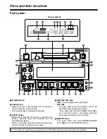
Front panel
6
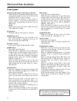
REPEAT lamp
This lights during repeat playback.
<Note>
The lamp flashes and repeat playback is not
performed if the counter display mode which has
been set using menu items No.161 [CTL (TC) BGN]
and No.162 [END] is at variance from the counter
display mode used for repeat playback.
7
SYSTEM format lamp
This indicates the status of the mode which has
been selected by menu item No.15 [SYSTEM
FREQ].
On:
59/60 Hz mode
Off:
50 Hz/25 PsF mode
Flashing:
23/24 Hz mode
2
, 25 Hz mode
2
8
SCH lamp
2
When SD signals are supplied to the HD/SD REF
VIDEO IN connector, this lights while the subcarrier
phase of the signals is within the prescribed range.
9
SERVO lamp
This lights when the drum servo or capstan servo is
locked.
:
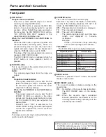
Channel condition lamps
The lamp corresponding with the error rate status
lights to indicate the channel condition.
(Green
5
white
5
red)
Green :
This lights when the error rates of both the
video and audio playback signals are
satisfactory.
White :
This lights when the error rate of either the
video playback signals or audio playback
signals has deteriorated. Normal playback
images appear even while it is lighted.
Red
:
This lights when correction or interpolation
is initiated for either the video playback
signals or audio playback signals.
;
Level meter
This indicates the levels of the audio signals.
The levels of the input signals are shown during
recording
2
or E-E
2
selection, and the levels of the
output signals are shown during playback.
<
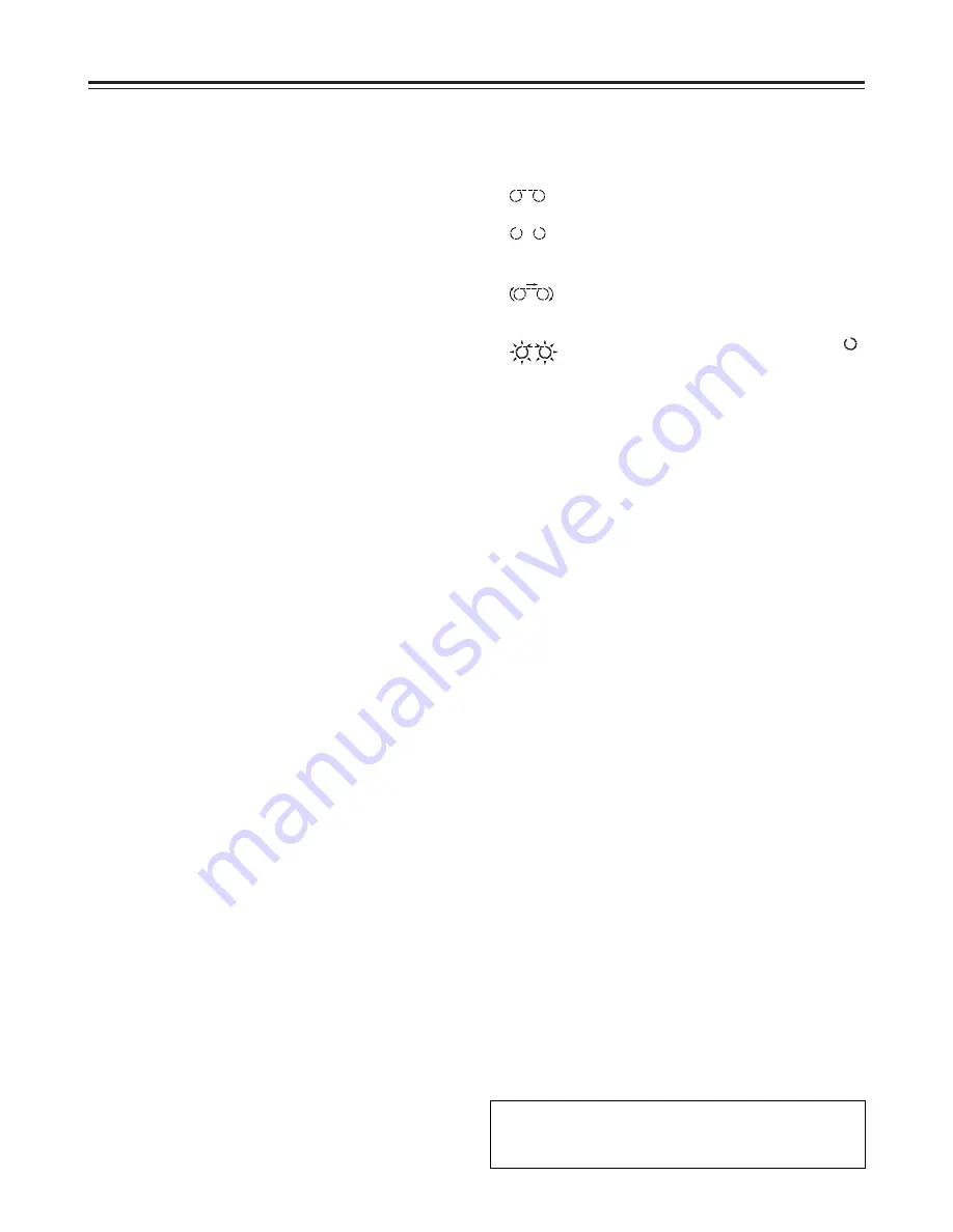
Cassette insertion/tape travel indicator lamp
This lights when a cassette is inside the unit.
:
This appears when a tape is inserted and
the STANDBY ON mode is established.
:
This appears when a tape is inserted and
the STANDBY OFF (HALF LOADING)
mode is established.
:
This appears when the tape is traveling,
and the segment display moves as the
tape travels.
:
When the fan has shut down, the “
”
corresponding to the stopped side flashes.
=
Counter display
This displays the TC and CTL counts, user’s bit
(UB), remaining tape length and total tape length as
well as the on-screen information and other
messages.
If the voltage drops when the unit is powered with
DC power supply, the display flashes to provide a
warning.
When the voltage drops down to 10.6 V or so, the
unit’s power is automatically turned off. (When
“TYPE-A” or “TYPE-B” is not selected as the menu
item No.180 [BATTERY SEL] setting)
CTL, TC and UB lamps
The corresponding lamps flash when the TC and
UB information cannot be read during playback.
The lamps remain lighted when the information can
be read properly.
>
LOCAL/MENU/REMOTE switch
Use this switch to select the menu settings or
control the unit from an external device.
LOCAL:
Select this position when the unit is to be
operated using the controls on its operation
panel.
MENU:
Select this position to perform on-screen menu
settings.
REMOTE:
Select this position when the unit is to be
operated using the external remote controller
(AJ-A95).
Parts and their functions
2
This function is operational only when the AJ-
YA120AG (optional accessory) has been
installed.
Summary of Contents for AJ-HD1200A-E
Page 55: ...Memo ...


