background image

– 134 –

Item

FRONT POWER

FRONT MIC

REAR MIC CH1

REAR MIC CH2

LINE CH1/CH2

REAR AUDIO

MIC LOWCUT
CH1

MIC LOWCUT
CH2

Variable

range

ON
OFF

p

40/

p

50/

60 dB

p

40

/

p

50

/

p

60 dB

p

40

/

p

50

/

p

60 dB

o

4/0/

p

6 dB

STEREO

MONO

FRONT
REAR
F&R
OFF

FRONT
REAR
F&R
OFF

Remarks

ON: The phantom power is supplied
to the front microphone.
OFF: The phantom power is not
supplied to the front microphone.

This selects the camera mic input
level.

This selects the mic level of the rear
AUDIO CH1 input jack.

This selects the mic level of the rear
AUDIO CH2 input jack.

This selects the line input level of the
rear AUDIO CH1 and CH2 input jacks.

This selects the rear jack AUDIO CH1
and CH2 input method.
STEREO: Stereo input is selected.
(The CH1 input signals are recorded
on CH1 and the CH2 input signals are
recorded on CH2.)
MONO: Monaural input is selected.
(The CH1 and CH2 input signals are
mixed, and the mixed signals are
recorded on both CH1 and CH2.)

FRONT: The CH1 input high-pass
filter is set to ON only when FRONT is
selected.
REAR: The CH1 input high-pass filter
is set to ON only when REAR is
selected.
F&R: The CH1 input high-pass filter is
set to ON regardless of whether
FRONT or REAR is selected.
OFF: The CH1 input high-pass filter is
set to OFF.

FRONT: The CH2 input high-pass
filter is set to ON only when FRONT is
selected.
REAR: The CH2 input high-pass filter
is set to ON only when REAR is
selected.
F&R: The CH2 input high-pass filter is
set to ON regardless of whether
FRONT or REAR is selected.
OFF: The CH2 input high-pass filter is
set to OFF.

VF

display

ENG

ENG

ENG

ENG

ENG

ENG

ENG

ENG

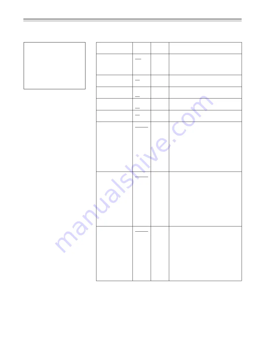
MAIN Menu Screen 3 of 4 (SUB menus)

MIC/AUDIO screen

The MIC/AUDIO items are set on this screen.

|

Note

{

Á

The frequency response when
ON is selected for the MIC
LOWCUT item setting is 200 Hz
to 10 kHz.

The underlining in the variable range column indicates the setting in the preset mode.

USER menu: The USER menu appears when the MENU switch is set to SET.
ENG menu:

The ENG menu appears when the MENU switch is set to SET while the SHIFT/ITEM button and UP button are
held down together.

{

M I C/A U D I O

A U D I O

F RON T
F RON T

P OWE R

:
:
:
:
:
:
:
:
:
:
:

ON

M I C

M I C

4 0 d B

4 d B

6 0 d B

6 0 d B

R E A R

C H 1

C H 1

C H 1

M I C

M I C

R E A R

R E A R

C H 2
C H 2

L I N E

/

µ

S T

T

E R

R

E O

O

L OW C U T

C H 2

M I C

L OW C U T

EMP H A S I S

O F

F

F

L I M I T E R

O F F

T

T

E S T

O E

N

N

N

T

RO

F

N

ORMA L

¢|

Summary of Contents for AJ-D810A

Page 1: ...AJ P Operating Instructions Digital Camera VTR ...

Page 2: ...e pursuant to Part 15 of the FCC Rules These limits are designed to provide reasonable protection against harmful interference when the equipment is operated in a commercial environment This equipment generates uses and can radiate radio frequency energy and if not installed and used in accordance with the instruction manual may cause harmful interference to radio communica tions Operation of this...

Page 3: ...38 ÁMounting the AJ MH700P Microphone Holder Option 39 Bold letters should be set or adjusted immediately after purchase ÁUsing the Microphone not Mounted to the Main Unit 40 ÁMounting a Wireless Microphone 41 Connecting an Audio Component 41 Mounting the Unit to a Tripod 42 Mounting the Shoulder Belt 43 Adjusting the Shoulder Pad Position 44 Attaching the Rain Cover 45 Connecting the AQ EC1 Exten...

Page 4: ...T Button 106 Replacing the Backup Battery 107 Setting Menu Screens MAIN menu 108 ÁMAIN menu screen 1 of 4 SUB menu 112 ROP 112 MATRIX 113 LOW SETTING 114 MID SETTING 115 HIGH SETTING 116 ADDITIONAL DTL 117 SKIN TONE DTL 118 KNEE LEVEL 119 FLARE GAMMA 120 CAMERA SETTING 120 ÁMAIN menu screen 2 of 4 SUB menu 121 VF DISPLAY 121 VF INDICATOR 123 CAMERA ID 124 SHUTTER SPEED 124 SYNCHRO SCAN 125 LED 125...

Page 5: ...dividually or according to the shooting conditions allowing the same setup conditions to be easily reproduced and assisting in standardizing setup conditions between individual data An ATA flash memory card with a memory size of 4 MB or more is required to operate the Picture Link Pix Link function sold as an optional accessory High function electronic shutter Using the built in electronic shutter...

Page 6: ...olor bar and reference audio signals The camera section contains a circuit which generates an SMPTE type color bar signal to facili tate color monitor adjustments and a circuit which generates a reference level audio signal to facilitate audio level adjustments The unit also contains a circuit for generating SNG color bar signals which come in handy for sending signals to communication satellites ...

Page 7: ...sing the 26 pin 12 pin output adaptor option AJ YA900P recording can be performed by the external VTR instead of the internal VTR Remote control Connecting the Extension Control Unit option AQ EC1 allows a portion of the camera section functions to be operated by remote control ...

Page 8: ...e output from the unit s VIDEO OUT connector Built in time code generator reader Time code information can be recorded and played back on a dedicated subcode track Locking of the time code to an external source The built in time code generator can be locked to an external generator Also the built in time code generator uses a lithium battery as its back up power supply allowing time codes to be ba...

Page 9: ...ptor AJ B75 Sony Battery BP 90 BP L60 BP L90 Panasonic Battery AU BP220 Sony Battery NP 1 Panasonic Battery AU BP402 Anton Bauer Battery Battery charger AG B425 Rain cover SHAN RC700 Soft carrying case AJ SC900 Tripot mount adaptor SHAN TM700 Extension control unit AQ EC1 Cleaning tape AJ CL12MP Cassette tape ÁM size cassette tape exclusively for DVCPRO Setup memory card SHL 064HSRVS 5w EVF mount ...

Page 10: ...external battery is to be used to operate the unit g BREAKER circuit breaker button In order to protect the equipment the circuit breaker is tripped and the power is automatically turned off when an excessively high level of power flows inside Upon completion of the internal inspection and adjustments push this button back in The power will come back on provided that there is no trouble inside the...

Page 11: ...place if the lens is not going to be mounted n Lens cable clamp This is for clamping the lens cable o Tripod mount When the unit is to be secured to a tripod mount the tripod attachment SHAN TM700 which is available as an optional accessory p LENS connector 12 pin Hook up the lens connecting cable to this connector Consult with your dealer concerning the lens which you are going to use q Shoulder ...

Page 12: ...udio input selector switch This selects the input signals to be recorded on audio channels 1 and 2 FRONT MIC The microphone input signals connected to the MIC IN jack s are recorded REAR MIC The microphone input signals connected to the AUDIO IN CH1 CH2 connec tors y are recorded REAR LINE The line input signals connected to the AUDIO IN CH1 CH2 connectors y are recorded w REAR MIC POWER switch ON...

Page 13: ...cted to the PHONES jack MONITOR SELECT audio channel selector switch This selects the audio channel whose sound is to be heard through the speaker AUDIO OUT connector z or earphone CH1 The audio channel 1 sound is output 1 2 The sound produced by mixing the audio channel 1 and 2 sound or the stereo sound is output However only the mixed sound is output from the speaker and AUDIO OUT connector z CH...

Page 14: ...inside the viewfinder ON The zebra pattern is displayed OFF The zebra pattern is not displayed When the unit is shipped from the factory the zebra pattern is set in such a way that those parts with an IRE video level from approx 70 to 85 are displayed The displaying of parts with a level ranging from 50 to 110 or more or with a certain level can also be set on the setting menu Diopter control knob...

Page 15: ...E BAL white balance memory selector switch PRST Set to this position when there is no time to adjust the white balance The white bal ance value for 3200K is stored in the memory A or B When the AUTO W B BAL switch is pressed to the AWB side the white balance is automatically adjusted in accordance with the setting position of the filter knob and the adjustment value is stored in memory A or memory...

Page 16: ...ion on the viewfinder screen Example 12 dB AUTO W B BAL white balance black balance automatic adjustment switch AWB Set to this position for automatically adjusting the white balance When the WHITE BAL switch is now set to A or B the adjusted value will be stored in memory A or memory B ABB Set to this position for automatically adjusting the black balance When this switch is held down for at leas...

Page 17: ...ptional accessory to the 12 pin connector it is possible to output the sound of audio channels 1 and 2 separately µ VIDEO OUT connector BNC This outputs the video signals 75 termination rated level to be monitored During recording EE images can be monitored during playback playback images can be monitored While performing settings on the menu the setting menu can be superimposed onto the shot imag...

Page 18: ... to standby mode press the VTR SAVE STBY switch once to select SAVE mode then once again to return to STBY mode MODE CHECK button While this button is kept depressed the camera s setting status is displayed in the viewfinder It does not affect the camera s output signals º SUPER GAIN button inside sliding cover The super gain mode is forcibly established when this button is pressed and each time t...

Page 19: ...utton Press this to fast forward the tape Its lamp lights during fast forwarding If this button is pressed during playback the playback images are fast forwarded at approxi mately quadruple speed while the button is held down À PLAY PAUSE button Press this to view the playback images on the viewfinder screen or color video monitor Its lamp lights during playback If this button is pressed again dur...

Page 20: ...e This switch functions differently depending on the operation item Check the function by oper ating the menu item by item Æ UP button This is used to increment the setting of the item selected on the setting menu by 1 level each time it is pressed or to switch the setting between ON and OFF Ç DOWN button This is used to decrement the setting of the item selected on the setting menu by 1 level eac...

Page 21: ...r example Í RESET button This resets the time data on the counter display to 00 00 00 00 When the TCG switch Ñ is set to SET and this button is pressed the time code or user s bit can be reset to 00 00 00 00 or 00 00 00 00 Î DISPLAY switch The time code CTL or user s bit is made to appear on the counter display depending on the setting positions of this switch and the TCG switch Ñ UB The user s bi...

Page 22: ...ng by the VTR section It flashes in the same way as the REC lamp inside the viewfinder to warn the operator The brightness when lighted can be selected using the TALLY switch HIGH or LOW Ó TALLY switch This controls the tally lamp Ò HIGH The tally lamp is made brighter OFF The tally lamp is extinguished LOW The tally lamp is made darker Ô Back tally lamp This functions in the same way as the tally...

Page 23: ...lide it into place 2 When detaching the battery hold down the detachment lever of the battery holder and slide the battery pack in the direction of the arrow Note The AJ D910WA supports the intelligent battery system and the ultra light system Automatic detection can be performed for intelligent batteries with a remaining battery level of 10 or more At this time the remaining battery level is disp...

Page 24: ... case 3 Mount the AU M402H battery case Open the battery case cover and lift up the rubber cap to expose the screw holes Tighten the screws with a screwdriver and mount the case to the unit Be sure to tighten the screws completely Notes ÁDo not pull strongly on the rubber cap ÁTake care not to catch the connection cord between the battery case and the main unit ...

Page 25: ... 25 4 Connect the battery pack plug to the connector inside the case and insert the battery pack Note The unit s power must be set to OFF before the plug is inserted or removed Power Supply ...

Page 26: ...d cover as shown in the figure A Tighten the mounting screws B Tighten the power supply contact screws C Insert the top of the detached cover in the direction of the arrow D Align the hole at the bottom metal part of the cover with the hole at the bottom of the case and mount the cover to the battery mounting connector with the screw of the battery holder Note Take care when attaching the battery ...

Page 27: ...e cover to the battery mounting connector with the screw Using the Sony BP L60 BP L90 lithium ion Battery Pack 1 Attach the supplied battery mounting terminals 2 Attach the lithium ion battery holder A As shown in the figure remove the battery clamp and attach the holder using the mount ing screws B Tighten the power supply contact screws C Put the battery clamp back into place Notes ÁThe unit s p...

Page 28: ...power supply other than the AJ B75 AC adaptor check the pin signal of the EXT DC IN socket ÁWhen both a battery pack and AC adaptor are connected power is supplied from the AC adaptor ÁWhen using an AC adaptor the AC adaptor s power must be set to ON before the unit s POWER switch is set to ON If this sequence is reversed the AC adaptor s output voltage will rise slowly and may cause the unit to m...

Page 29: ...lect the type of battery 1 When the MENU SET OFF switch is set to SET while the HOLD button is pressed the battery selection menu appears on the screen 2 Press the SHIFT ITEM button and move the arrow cursor to BATTERY SEL 3 Press the UP or DOWN button to select the type of battery The type of battery is displayed here NiCd12 NiCd13 NiCd14 IDX L 40 L 60 L 90 ANTON D IDX D Display seen inside the v...

Page 30: ...and clamp the lens 4 Press the cable into the cable clamp and connect it to the LENS connector ÁSee the Handling Instructions provided with the lens for lens handling Note The lens and camera adjustments listed below may be necessary depending on the lens to be mounted 1 Lens flange back adjustment 2 Lens auto iris adjustment 3 Lens white shading adjustment with this unit Lens Clamping Lever Mount...

Page 31: ...ange back adjustment chart about 10ft 3 m from the lens and illuminate it so that an appropriate image output level is obtained Use the filter and or shutter if the video level is too high 3 Loosen the Ff ring clamping screw 4 Set the zoom ring to the telephoto position manually or by electric drive 5 Shoot the flange back adjustment chart and turn the distance ring to bring the chart into focus 6...

Page 32: ...TECT to 85 and ZEBRA2 to SPOT Initial setting mode Return the MENU SET OFF switch from SET to OFF to close the menu Set the viewfinder s ZEBRA switch to ON 5 Shoot an evenly white paper Flickering occurs easily when fluorescent or mercury lamps etc are used for lighting Therefore use a light source which does no produce flickering such as sunlight or halogen lamps etc 6 Set the lens iris to manual...

Page 33: ...y disappears Return the MENU switch from SET to OFF to close the menu 10 When the lens to be used has an extender insert an extender and repeat steps 6 to 9 11 If the lens used comes with a ratio converter insert the ratio converter and repeat steps 6 and 7 This completes white shading adjustment The adjustment value is stored in the non volatile memory so there is no need to readjust the white sh...

Page 34: ...er forward backward left right position clamp lever to release the lock 2 Adjust the position of the viewfinder in the forward backward and left right directions 3 Tighten the viewfinder forward backward left right position clamp lever to the locked position Viewfinder Lever ...

Page 35: ...he BRIGHT control Contrast Adjust the CONTRAST control Contour Adjust the PEAKING control 1 Set the POWER switch to ON 2 Set the OUTPUT switch to CAM 3 Turn the viewfinder BRIGHT and CONTRAST controls to adjust the picture brightness and contrast Turning the PEAKING control makes the picture appear softer or sharper A sharp picture facilitates focusing the lens Adjusting the Eyepiece Position Turn...

Page 36: ...n specially treated Dust which has adhered to the mirror should be blown away with a blower etc 1 Press the lock button 2 Turn the lock ring as far as possible in the counter clockwise direction and line up the align ment marks on the lock ring and viewfinder barrel 3 Detach the eyepiece Remounting the eyepiece 1 Line up the alignment marks on the lock ring and the viewfinder barrel and then inser...

Page 37: ...g in damage to the viewfinder 3 Loosen the viewfinder stopper screw and detach the viewfinder by pulling it straight up Mounting the Viewfinder 1 Press down the viewfinder 2 Tighten the viewfinder stopper screw firmly If it is difficult to insert the screw press down the viewfinder once again 3 Connect the plug to the viewfinder connector and secure the viewfinder cable with the clamp Note Insert ...

Page 38: ...e AJ MH700P microphone holder option al lows a microphone to be mounted to the main unit ÁSee the Handling Instructions for the microphone holder Using the AJ MC700P Microphone Kit Option Microphone Mounted to the Main Unit 1 Mount the microphone holder 2 Mount the microphone 3 Connect the microphone connecting cable to the unit s MIC IN jack Microphone Holder Viewfinder MIC IN Connector ...

Page 39: ... microphone adaptor option to the main unit 3 Mount the microphone to the microphone holder and tighten the screws 4 Connect the microphone connecting cable to the MIC IN jack 5 Set the AUDIO IN switch to FRONT MIC in accordance with the audio channel to be re corded Mount the microphone adaptor using the accessory screws To the MIC IN Connector ...

Page 40: ...itches of the channels to which microphones are connected to REAR MIC Audio Input Preparations Using the Microphone not Mounted to the Main Unit Note When extending the microphone use a cable which supports the phantom power supply type of microphone Using the Microphone not Mounted to the Main Unit AUDIO IN switch Set the AUDIO IN switch for the audio channel you wish to record to FRONT MIC To th...

Page 41: ...nectors To the AUDIO OUT Connector WX RA700 Wireless Receiver WX R980 Camera Attachment AJ D810A Main Unit XLR Cable Connect to the AUDIO IN CH1 or CH2 Connector AUDIO IN switch Set the AUDIO IN switch of the channel to which the audio signal source is connected to REAR LINE When detaching the wireless microphone press up the lever on the bottom of the camera attachment 1 and detach the microphone...

Page 42: ...hen the tripod attachment pin does not return to its original position after the camera has been detached hold down the red lever and move the black lever in the direction of the arrow again to return the pin to its original position Care should be taken as the camera cannot be mounted if the pin remains in the center Tripod Attachment 2 Mount the camera to the tripod attachment Slide the unit for...

Page 43: ...Note When mounting and removing the shoulder belt press on the top of the hooks to check that the belt is securely mounted Shoulder Belt Press to open the hook To remove the shoulder belt open the hooks and then remove the belt Press ...

Page 44: ...n from the center position the position when shipped from the factory Adjust the shoulder pad position to facilitate opera tion of the unit 1 Loosen the two screws 2 Slide the pad in the forward backward direction to select an appropriate position 3 Tighten the screws to clamp the pad Bottom Screws Shoulder Pad ...

Page 45: ...he Rain Cover Attach the rain cover as shown in the figure below Secure the surface fastener Tighten the Cord When mounting the unit to the tripod attachment mount the unit using this hole Secure the surface fastener ...

Page 46: ...ction of the AQ EC1 are erased when the unit s POWER switch is set to OFF Neither is it possible to save any of the adjustments and settings except for the menu settings performed using the AQ EC1 s switches and controls on the setup card However when the AQ EC1 is connected again these settings return to the AQ EC1 settings Menu contents set with the menu setting section are saved ÁWhen ON has be...

Page 47: ... 113 LOW SETTING 114 MID SETTING 115 HIGH SETTING 116 ADDITIONAL DTL 117 SKIN TONE DTL 118 KNEE LEVEL 119 FLARE GAMMA 120 CAMERA SETTING 120 VF DISPLAY 121 VF INDICATOR 123 CAMERA ID 124 SHUTTER SPEED 124 SYNCHRO SCAN 125 LED 125 CAMERA SW MODE 126 SUPER GAIN 127 VTR FUNCTION 128 BATT TAPE ALARM 130 CARD READ WRITE 131 CARD R W SELECT 132 REC SIGNAL RET 133 MIC AUDIO 134 GENLOCK IRIS 136 VIDEO OUT...

Page 48: ...wn 2 The current low mid and high gain settings are displayed 3 Press the SHIFT ITEM button and move the arrow cursor to the LOW MID or HIGH GAIN menu item 4 Set the gain by pressing the UP or DOWN button Any value from p3 dB to o30 dB can be set GA I N M M M A S T ER GA I I I N H H D L O G P CO O W GA I N GA I N B A T T ERY S E L EC T R R S E L E E C T T B A B A T T ERY S S E L L CO OR R B A L d ...

Page 49: ...own 2 To select the color bar menu item press the SHIFT ITEM button and move the arrow cur sor to COLOR BAR 3 Select the color bar setting by pressing the UP or DOWN button The SMPTE or SNG setting can be selected GA I N M M M A S T ER GA I I I N H H D L O G P CO O W GA I N GA I N B A T T ERY S E L EC T R R S E L E E C T T B A B A T T ERY S S E L L CO OR R B A L d N i C 1 2 0 d B 9 d B d B 1 8 ...

Page 50: ...shown in the figure below appears and it is now possible to check the DIAGNOSTIC screen settings 4 To close the menu screen return the MENU SET ON OFF switch to OFF D I AGNOS T I C OP ERA T I ON 0 0 0 0 0 1 DRUM RUNN I NG T HRE AD I NG V T R S Y SCON S Y SCON V e r P CAM DA T ROM A 0 1 0 0 V e r 1 0 1 0 V e r 1 0 DV V e r 1 0 0 h 0 0 0 0 0 1 0 0 0 0 0 0 1 0 h ...

Page 51: ... be used In addition the data set at each page is written to the non volatile memory allowing it to be stored for extended periods of time If upon completion of the adjustments and settings in the engineer mode the menu is set to be configured only with the frequently used pages the pages which are often needed can be called promptly Select the method using the user menu selection procedure descri...

Page 52: ...he SHIFT ITEM button and UP button are held down together MAIN menu screen 1 of 4 now appears The pages can also be selected using the UP and DOWN buttons in combination with the PAGE button as indicated below ÁPAGEµUP When the UP button is pressed while the PAGE button is held down opera tion advances to the next menu and the menu next to it and so on for as long as the button is held down ÁPAGEµ...

Page 53: ... E T T I NG M I D H I GH ADD I T I ONA L D T L D T L S K I N TONE KNE E L E V E L F L ARE GAMMA CAMERA V F V F D I S P L A Y I ND I CA TOR CAMERA CAMERA I D SHU T T ER S P E ED S YNCHRO SCAN L ED SW MODE SUP ER GA I N V T R F UNC T I ON B A T T T A P E A L ARM E E E E E E E E Displaying Menus on the Viewfinder Screen To select a MAIN menu page 1 Press the PAGE button to select a particular MAIN me...

Page 54: ...is decremented by 1 level each time the DOWN button is pressed Changing the ON OFF selection The setting switches to ON or OFF each time the UP or DOWN button is pressed Returning to the default settings Align the arrow with READ FACTORY DATA on the INITIALIZE SUB menu page of the MAIN menu screen 4 of 4 When the UP or DOWN button is now pressed the initial factory settings will be restored Howeve...

Page 55: ...e items set to ON at the LED page of the setting menu Applicable items are as follows ÁSee Setting the Lamp Display next page for selecting lamp display items 4 VTR SAVE VTR power saving lamp This lamp lights when the VTR SAVE STBY switch is set to SAVE It is not lighted during recording Note The SAVE status is automatically established and the lamp lights regardless of the VTR SAVE STBY switch po...

Page 56: ...ht when the gain is set to a value other than 0 dB GAIN 3 dB This selects whether the lamp is to light when the gain is set to a value other than p3 dB SHUTTER This selects whether the lamp is to light when the SHUTTER switch is set to the ON position WHITE PRESET This selects whether the lamp is to light when the white balance memory channel is set to PRST EXTENDER This selects whether the lamp i...

Page 57: ...g display items Display Mode and Setting Change Message page 61 for the setting change message and Setting the Marker Displays page 62 for the marker displays The display positions of all items which can be displayed are shown in the figure below e Extender display f Shutter speed mode display g Remaining tape length display h Remaining battery level display i Filter display j White balance memory...

Page 58: ...minutes 35 to 30 minutes 30 to 25 minutes 25 to 20 minutes 20 to 15 minutes 15 to 10 minutes 10 to 5 minutes 5 to 0 minutes The 5 0 display flashes when there is less than 2 minutes of tape remaining 4 Remaining battery level display When an Anton Bauer Digital Magnum Series battery is used to supply power to the unit the remaining battery level is displayed numerically Note When a Digital Magnum ...

Page 59: ...s indicates the center of the viewfinder screen The marker appears when its display is set to ON on the VF DISPLAY page of the setting menu 13 Super iris ON display This indicates that the super iris is ON 14 MARK1 MARK2 TAKE display If the MARK switch is pressed while the Picture Link function is used M1 or M2 appears to indicate the significance of the information concerned Nothing will appear i...

Page 60: ...the MENU SET OFF switch to the SET position while the SHIFT ITEM button and UP button are held down together 2 Press the PAGE button to display the MAIN menu screen 2 of 4 3 Press the SHIFT ITEM button to move the cursor to the VF INDICATOR position 4 Press the UP or DOWN button to open the VF INDICATOR page 5 Press the SHIFT ITEM button to move the cursor to the position of the disired item 6 Pre...

Page 61: ...e setting is changed When the white balance is adjusted AWB When the black balance is adjusted ABB Message Filter n nr1 2 3 4 GAIN n dB nrp3 0 3 6 9 12 15 18 GAIN 21 24 30 36 43 46 WHITE n nrACH BCH PRESET AUTO KNEE ON or OFF SS 1 100 or 1 120 1 250 1 500 SS 1 1000 1 2000 S SCAN SUPER V Ex AWB OK ÁSee Adjusting the White Balance page 70 for a detailed description Ex ABB OK ÁSee Adjusting the Black...

Page 62: ...ses ap pear at the top and bottom of the viewfinder screen Setting the Marker Displays ON or OFF is selected for the center mark and safety zone mark display and a ratio of 80 or 90 of the total screen area is set for the safety zone range on the VF DISPLAY SUB menu page of MAIN menu screen 2 of 4 1 Perform steps 1 to 4 under Changing the Display Mode described above so that the VF DISPLAY page ap...

Page 63: ...ERA ID position 4 Press the UP or DOWN button to open the CAMERA ID page The cursor is moved to the right max 10 spaces by the SHIFT ITEM button Alphanumerics symbols and spaces are selected by the UP and DOWN buttons 5 Keep pressing the UP or DOWN button until the character to be set appears Each time the UP button is pressed the character display changes in the following order space Å english le...

Page 64: ... when tape wind up trouble occurs ÁSee Warning System page 149 for a detailed description Lights DF SLAVE TCG HOLD Error code Indicated in the display window Remaining battery level When the digital display display battery is used the 7 segments light up all the way to the F position if the remain ing battery level is more than 70 If the remaining battery level is under 70 one of the seg ments goe...

Page 65: ...isplay items These lamps light to indicate the time code CTL and real time displays DF This lamp lights during drop frame mode SLAVE This lamp lights when the time code is locked to an external source HOLD This lamp lights when the time code generator is held when the HOLD button is pressed Time counter display This displays the time code CTL user bit and real time ÁSee below for the relationship ...

Page 66: ...button is pressed and decremented by p1 each time the DOWN button is pressed 7 When the settings have been completed press the SHIFT ITEM button to select TIME DATE SET and then press the UP or DOWN button The time starts from when the button is pressed 8 When menu operations have been completed set the MENU SET OFF switch to OFF The setting menu disappears from the viewfinder screen and the displ...

Page 67: ...nu are as follows Adjustment setup items at the setting menu Adjustment setup item Setting the gain selector value Selecting the shutter speed mode to be used Setting the synchro scan mode shutter speed Selecting the required VTR functions Shading adjustment Setup card data operations Page name SETTING LOW MID HIGH SHUTTER SPEED SYNCHRO SCAN VTR FUNCTION AUTO SHADING SET UP CARD Operation referenc...

Page 68: ... set 4 Press the UP or DOWN button to open the setting page 5 Press the SHIFT ITEM button to move the cursor to the MASTER GAIN position 6 Press the UP or DOWN button to set the gain value Any gain value can be set regardless of whether it is high or low from among the p3 0 3 6 9 12 15 18 21 24 and 30 dB setting options To reset the gain values to their factory settings LOWr0dB MIDr9dB HIGHr18dB s...

Page 69: ...Press the SHIFT ITEM button to move the cursor to the position of the function to be changed 6 Press the UP or DOWN button to change the setting of the selected function If settings for other functions are also to be changed return to step 5 7 When menu operations have been completed set the MENU SET OFF switch to OFF The setting menu disappears from the viewfinder screen and the displays indicati...

Page 70: ...ronization with the power line frequency even if the bright ness of these lights appears to be constant Especially in areas where the power line frequency is 50 Hz the vertical synchronizing frequency approx 60 Hz of the NTSC and the frequency 50 Hz of the lighting tend to interact This gives rise to flicker and to a phenomenon where the hue changes along with the passage of time and it is it impo...

Page 71: ...the white balance is automatically adjusted 6 During the adjustment the following message appears on the viewfinder screen However the message appears only when the display mode is set to 2 or 3 7 The adjustment is completed in several seconds and a message such as the one shown in the figure appears The adjustment value is automatically stored in the memory A or B which was selected in step 1 1 4...

Page 72: ... is higher than the one dis played Note If a lens equipped with the automatic iris function is used the iris may experience hunting1 In these cases adjust the iris gain knob the knob marked IG IS S etc on the lens ÁSee the Handling Instructions for the lens for a detailed description 1 Hunting The auto iris responds repeatedly causing the image to become darker and brighter AWB A OK 2 5 K AWB A OK...

Page 73: ... the error message continues to appear even after repeated attempts consult your dealer Notes ÁThe white balance will not be adjusted while the setting menu is displayed on the viewfinder screen The MENU SET OFF switch must be set to the OFF position to make this adjustment ÁIn rare instances the white balance adjustment may not be possible and an NG display will appear In a case like this proceed...

Page 74: ...inated by a light with a color temperature close to the one displayed If the color temperature of the subject in this state is close to 5 2K the white balance is adjusted and so operation is now possible Change to filter 3 5 2K 1 see Note appears on the display Note This display indicates that the AWB was adjusted using filter 1 Use filter 1 to adjust the AWB for objects with an illumination color...

Page 75: ...he SUPER GAIN button ÁWhen the gamma ON OFF is changed Adjusting the Black Balance 1 Set the switches as shown in the figure 2 Press the AUTO W B BAL switch to the ABB side and then release the switch The switch returns to the center and the black balance is automatically adjusted 3 During the adjustment the following message will appear on the viewfinder screen Howev er the message appears only w...

Page 76: ...wfinder screen but this does not indicate a malfunction ÁThe black balance cannot be adjusted while the setting menu is displayed on the viewfinder screen Therefore be sure to set the MENU SET OFF switch to OFF ÁIf the black shading is not satisfactory even when the ABB OK message appears open the AUTO SHADING SUB menu page of MAIN menu screen 4 of 4 and adjust the black shading See page 141 ÁThe ...

Page 77: ...d 1 2000 seconds Range from 60 3 Hz to 250 Hz Application This mode is used to shoot clear images of quickly moving subjects This mode is used to reduce horizontal stripe patterns for monitor screens with a vertical scanning frequency of 60 Hz or more This mode is used to increase the vertical resolution Notes ÁIncreasing the shutter speed lowers the camera sensitivity regardless of electronic shu...

Page 78: ...n the VF DISPLAY SUB menu page of MAIN menu screen 2 of 4 to 2 or 3 by following the steps outlined in Changing the Display Mode page 62 2 Press the SHUTTER switch from the ON position to the SEL side The current shutter setting appears in the setting change message display position on the viewfinder screen Ex 1 120 1 60 3 etc 3 Press the SHUTTER switch to the SEL side repeatedly until the desired...

Page 79: ...lue increases or DOWN the value decreases button repeatedly to display the desired frequency The frequency can be switched continuously within the range of 60 3 Hz to 250 Hz 6 When menu operations have been completed set the MENU SET OFF switch to OFF The setting menu disappears from the viewfinder screen and the displays indicating the unit s current status appear at the top and bottom of the vie...

Page 80: ...de or speed changes from used ON to not used OFF and vice versa each time the UP or DOWN button is pressed 7 When menu operations have been completed set the MENU SET OFF switch to OFF The setting menu disappears from the viewfinder screen and the displays indicating the unit s current status appear at the top and bottom of the viewfinder screen Note When operating the unit from the AQ EC1 extensi...

Page 81: ...appears up to 0 dB at the maximum volume Limiter When the audio level is adjusted manually the limiter circuit operates with respect to excessive input The limiter circuit is turned ON or OFF on the MIC AUDIO SUB menu page of MAIN menu screen 3 of 4 The factory setting is OFF Adjusting the Audio CH1 Level from the Viewfinder The audio CH1 level can be adjusted by the AUDIO LEVEL CH1 control at the...

Page 82: ...optimal level cannot be set The maximum attenuation of the AUDIO LEVEL CH1 control at the bottom of the front panel is about 20 dB When the optimal level cannot be set within this range adjust the level using the AUDIO LEVEL CH1 control on the side panel Using the AUDIO LEVEL CH1 controls at the bottom of the front panel and on the side panel Normally the control at the bottom of the front panel i...

Page 83: ... the SHIFT ITEM UP and DOWN buttons SHIFT ITEM button This is used to cause the digit which is to be set to flash Each time it is pressed the flashing digit moves to the right UP button This increments by 1 the figure of the flashing digit DOWN button This decrements by 1 the figure of the flashing digit 5 Set the TCG switch Set the switch to F RUN when the time code is to be advanced regardless o...

Page 84: ...mal characters A to F appear as follows 5 Set the F RUN R RUN switch to F RUN or R RUN User bit memory function The user bit setting except for the real time is automatically stored in the memory and held even after the power is turned off However care should be taken as the settings are not stored in the memory if the time from when the power was turned on until the setting operations are complet...

Page 85: ...the others as the slave units Reference video signal To the next unit External Lock Operation Procedure 1 Set the POWER switch to ON 2 Set the F RUN R RUN switch to F RUN 3 Set the DISPLAY switch to TC 4 Supply reference time code and reference video signals whose phases correlate in a way that meets the time code standards to the TC IN and GENLOCK IN VIDEO IN connectors respectively MASTER SLAVE ...

Page 86: ...a section is genlocked by the reference video signal which is supplied to the GENLOCK IN VIDEO IN connector Using the user data The setting menu contents can be saved in the user area of the camera s memory so that they can be loaded as and when required This data enables the suitable setup statuses to be re estab lished without delay User data operation A menu is used to save the data settings in...

Page 87: ...r and remove the setup card Note Take care not to touch the connectors at the front of the setup card Inserting setup cards Position the unit so that the panel with the logo faces you insert the setup card into the setup card insertion slot and then close the cover Note Check that the unit is positioned with the logo facing you and that the characters are facing the correct direction and then inse...

Page 88: ...y to move the cursor to the CARD CONFIG position 6 A menu shown below appears when the UP or DOWN button is pressed 7 Press the UP button to format the set up card When the setup card has been formatted the message shown below appears Note When setup cards are formatted the setting conditions at that time are also input simulta neously 8 When menu operations have been completed return the MENU SET...

Page 89: ... not written Data format error messages Set the write protect switch on the side of the card to OFF Insert a card The card may be defective Replace the card Error message WRITE PROTECT NO CARD ERROR Condition The write protect switch on the side of the card is set to ON A setup card is not inserted The disk cannot be formatted Countermeasure ...

Page 90: ...or DOWN button is pressed 7 Press the UP button to write data on the set up card When writing is complete the message shown below appears 8 When menu operations have been completed return the MENU SET OFF switch to OFF The setting menu disappears from the viewfinder screen and the displays indicating the unit s current status appear at the top and bottom of the viewfinder screen CARD CARD RE AD RE...

Page 91: ... is pressed in step 7 the data is not written Data writing error messages Set to ON Format the card Insert a card Set the write protect switch on the side of the card to OFF The card may be defective Replace the card Error message NO CONFIG NO CARD WRITE PROTECT ERROR Condition The setup card is not formatted A setup card is not inserted The write protect switch on the side of the card is set to O...

Page 92: ...tions have been completed set the MENU SET OFF switch to OFF The setting menu disappears from the viewfinder screen and the displays indicating the unit s current status based on the data read out from the setup card appear at the top and bottom of the viewfinder screen When data is not read out If the following error messages appear when the UP button is pressed in step 7 the data is not read out...

Page 93: ... the display goes off before proceeding to step 2 2 Press the EJECT button The cassette holder opens Power ON 3 Check there is no slack in the tape insert the cassette then press the PUSH display on the cassette holder to close the cassette holder firmly Checking that there is no slack in the tape Press the reel in with your finger and turn it lightly in the direction of the arrow If the reel does...

Page 94: ... cassettes when the battery has run out Set the POWER switch to OFF to turn off the power then turn on the power again and immediate ly hold down the EJECT button If there is still power remaining in the battery the cassette will be ejected However this operation should not be repeated Preventing Accidental Erasure Set the tab on the cassette to the SAVE side to prevent the recorded contents of ta...

Page 95: ...ON and check that the HUMID display does not appear and that five or more bars of the remaining battery level display are lighted ÁIf the HUMID display appears wait until the display goes off ÁIf five or more bars of the remaining battery level display are not lighted replace the battery pack with a sufficiently charged battery pack 3 Check that there are no cables etc around the cassette holder a...

Page 96: ...balance to stopping recording Turn on the power insert a cassette and then set the various switches as follows Iris AUTO AUDIO SELECT CH1 CH2 AUTO TCG F RUN or R RUN OUTPUT CAM AUTO KNEE ON GAIN Normally set to 0 dB When it is too dark it is set to the appropriate gain ...

Page 97: ... balance 2 Press the AUTO W B BAL switch to the ABB side to adjust the black balance 3 Press the AUTO W B BAL switch to the AWB side to adjust the white balance For details on how to adjust the white balance read through the section entitled Adjusting the white balance black balance page 70 2 Aim the camera at the subject and adjust the focus and zoom 3 When using the electronic shutter set the sh...

Page 98: ...er the time until record ing starts differs according to the setting of the VTR SAVE STBY switch ÁIf the VTR SAVE STBY switch is set to SAVE recording starts about 2 seconds after the VTR START button is pressed ÁIf the VTR SAVE STBY switch is set to STBY recording starts immediately after the VTR START button is pressed Successive shooting when the power is turned off while recording is paused 1 ...

Page 99: ...ow 1 While monitoring the viewfinder screen press the PLAY PAUSE button to play back the tape 2 At the place where a new recording is to continue on from the existing recording press the PLAY PAUSE or STOP button again to stop the tape 3 Press the RET button on the lens Preparations for frame to frame continuity are made about two seconds later 4 Press the VTR START button of the unit or the VTR b...

Page 100: ...even during rewind REW and fast forward FF Audio output selection and volume adjustment for the playback signal are performed by the MON ITOR switches and knobs on page 13 Rec Review If recording is paused and the RET button on the lens is pressed the tape is automatically re wound and the playback images for the last two seconds appear on the viewfinder This allows the recording status to be chec...

Page 101: ... display func tion inside the viewfinder indicate the power supply status only for the internal VTR The power supply status for the external VTR should be checked at the external VTR TALLY lamp and REC lamp operation The unit s TALLY lamp and the REC lamp inside the viewfinder indicate the REC status of the unit when 26P CONTROL is set to BOTH When 26P CONTROL is set to ON these lamps indicate the...

Page 102: ...gain sets both VTRs to the recording paused status If One VTR Comes to the End of its Tape During Recording Even if one VTR comes to the end of its tape and stops the other VTR continues recording oper ation Returning the VTRs to simultaneous recording status ÁIf the internal VTR came to the end of its tape replace the cassette and press the VTR START button of the unit or the VTR button of the le...

Page 103: ...rd modes respectively However the external VTR is set to recording paused status in all cases Viewing playback images on the viewfinder Pressing the PLAY PAUSE button allows black and white images from the tape of the internal VTR to be viewed on the viewfinder screen To view return images of an external VTR on the viewfinder screen set RET SW on the REC SIGNAL RET SUB menu page to CAM RET and pre...

Page 104: ... the unit s internal switches 1 Remove the side panel on the display window side 2 Remove the printed circuit board holder and take out the CAM ENC 2 printed circuit board 3 Set SW201 to the ON side 4 Take out the SYNC 3 printed circuit board 5 Set SW1 26PIN to the ON side 6 To set the audio level to p20 dB set the SW4701 DIP switch accordingly CAM ENC 2 Printed Circuit Board Printed Circuit Board...

Page 105: ...T button on the unit and the VTR button on the lens will cease to function In these cases it will be possible to operate the external VTR in place of the internal VTR using the VTR START button on the unit and the VTR button on the lens if the 26P CONTROL function on the VTR FUNCTION page is set as indicated above Starting recording Operate the external VTR to set it to recording paused status and...

Page 106: ...nction Recording paused What has been recorded 2 second rec review can be checked Playing Internal VTR s playback images RET button does not function Playback paused Search operation for successive shooting CAM RET Recording Return video signal which has been supplied to GENLOCK IN VIDEO IN connector Recording paused Return video signal which has been supplied to GENLOCK IN VIDEO IN connector Play...

Page 107: ...s out the TCG time code value indicates 00 00 00 00 At this time the time code value cannot be backed up In addition the BACK UP BATT EMPTY display appears in the viewfinder for 3 seconds when the POWER switch is set to ON to indicate that the battery must be replaced Consult your dealer when replacing the battery Backup battery ...

Page 108: ...E GAMMA CAMERA SETTING VF display USER ENG USER ENG USER ENG USER ENG USER ENG USER ENG USER ENG USER ENG USER ENG USER ENG Remarks Index for opening the ROP SUB menu Index for opening the MATRIX SUB menu Index for opening the LOW SETTING SUB menu Index for opening the MID SETTING SUB menu Index for opening the HIGH SETTING SUB menu Index for opening the ADDITIONAL DTL SUB menu Index for opening t...

Page 109: ...SPLAY SUB menu Index for opening the VF INDICATOR SUB menu Index for opening the CAMERA ID SUB menu Index for opening the SHUTTER SPEED SUB menu Index for opening the SYNCHRO SCAN SUB menu Index for opening the LED SUB menu Index for opening the CAMERA SW MODE SUB menu Index for opening the SUPER GAIN SUB menu Index for opening the VTR FUNCTION SUB menu Index for opening the BATT TAPE ALARM SUB me...

Page 110: ...Remarks Index for opening the CARD READ WRITE SUB menu Index for opening the CARD R W SELECT SUB menu Index for opening the REC SIGNAL RET SUB menu Index for opening the MIC AUDIO SUB menu Index for opening the GENLOCK IRIS SUB menu Index for opening the VIDEO OUT menu Index for opening the TIME DATE SUB menu Index for opening the LENS SEL ADJ SUB menu E E E E E E E E MA I N MENU 3 4 CARD RE AD WR...

Page 111: ... N I T I A L I Z E D I AGNOS T I C E E E E E E E E SUB menu USER MENU SEL 1 3 USER MENU SEL 2 3 USER MENU SEL 3 3 AUTO SHADING EVALUATION INITIALIZE DIAGNOSTIC VF display USER ENG USER ENG USER ENG USER ENG USER ENG USER ENG USER ENG Remarks Index for opening the USER MENU SEL 1 of 3 SUB menu Index for opening the USER MENU SEL 2 of 3 SUB menu Index for opening the USER MENU SEL 3 of 3 SUB menu In...

Page 112: ... P EDE S T A L G B Item MASTER PED MASTER DTL MASTER GAMMA R GAIN B GAIN R PEDESTAL G PEDESTAL B REDESTAL Remarks For setting the master pedestal level This sets the H DTL V DTL level This sets the master gamma in 0 01 increments Different settings for LOW MID and HIGH can be stored in the memory This sets the R channel gain This sets the B channel gain This sets the R channel pedestal level This ...

Page 113: ...ld down together MAIN Menu Screen 1 of 4 SUB menus MATRIX screen The camera s matrix settings are performed on this screen MA T R I X MA T R I X MA T R I X MA T R I X MA T R I X MA T R I X MA T R I X MA T R I X T A A B L E µ1 1 µ0 9 µ0 5 µ1 5 µ1 1 µ1 1 R G R B G R G B B R B G Item MATRIX TABLE MATRIX R G MATRIX R B MATRIX G R MATRIX G B MATRIX B R MATRIX B G Variable range A B p31 o11 o31 p31 o9 o...

Page 114: ...il level This sets the V DTL detail level This sets the DTL coring This selects the H DTL frequency 1 2 5 MHz 4 4 MHz 2 3 MHz 5 4 5 MHz 3 3 5 MHz This sets the dark detail This boosts the detail of the black areas This sets LEVEL DEPEND This eliminates the detail only in the dark areas when the Y detail is boosted The higher the number selected the wider the range across which the detail is elimin...

Page 115: ...K S T RE T CH OF F T A B L E A MA T R I X Item MASTER GAIN H DTL LEVEL V DTL LEVEL DTL CORING H DTL FREQ DARK DTL LEVEL DEPEND MASTER GAMMA BLACK STRETCH MATRIX TABLE Variable range p3 dB 9 dB 30 dB 0 10 31 0 10 31 0 6 15 1 3 5 0 5 0 3 15 0 35 0 45 0 75 ON OFF A B OFF Remarks This sets the gain to p3 0 3 6 9 12 15 18 21 24 or 30 dB This sets the H DTL detail level This sets the V DTL detail level ...

Page 116: ...K S T RE T CH OF F T A B L E A MA T R I X Item MASTER GAIN H DTL LEVEL V DTL LEVEL DTL CORING H DTL FREQ DARK DTL LEVEL DEPEND MASTER GAMMA BLACK STRETCH MATRIX TABLE Variable range p3 dB 18 dB 30 dB 0 10 31 0 10 31 0 10 15 1 3 5 0 5 0 8 15 0 35 0 45 0 75 ON OFF A B OFF Remarks This sets the gain to p3 0 3 6 9 12 15 18 21 24 or 30 dB This sets the H DTL detail level This sets the V DTL detail leve...

Page 117: ...he greater the level of compensation provided This selects ON or OFF for the knee aperture This boosts the detail above the knee point This selects ON or OFF for mode in which the detail is made finer This selects ON or OFF for mode which increases the resolution at the edges of the screen This changes the H detail level in the o direction This changes the H detail level in the p downward directio...

Page 118: ...lected the wider the skin tone range This sets the skin tone coring The amount of detail in the skin tone range is changed This selects ON or OFF for ZEBRA in the skin tone range This changes the coring in the range across which ZEBRA can be seen VF display ENG ENG ENG ENG ENG ENG The underlining in the variable range column indicates the setting in the preset mode USER menu The USER menu appears ...

Page 119: ...switch is set to OFF This sets the manual knee point position This sets the manual knee slope This selects ON or OFF for the white clip This sets the white clip level This sets the automatic knee point position This sets the maximum level of the automatic knee VF display ENG ENG ENG ENG ENG ENG ENG ENG ENG The underlining in the variable range column indicates the setting in the preset mode USER m...

Page 120: ... color above the knee point This selects ON or OFF for the gamma correction This selects ON or OFF for the test signal This selects ON or OFF for the flare compensation This selects ON or OFF for the mode in which the high frequency detail is enhanced This selects ON or OFF for the DTL signal from the setup level 7 5 to the blanking level VF display ENG ENG ENG ENG ENG ENG ENG ENG CAMERA S E T T I...

Page 121: ...among the R G and B signals are output This selects the VF detail The detail of the VF signals is further boosted At the 0 setting the detail is the same as for the main line signals This sets the ZEBRA1 detection level IRE value This sets the ZEBRA2 detection level IRE value VF display USER ENG USER ENG USER ENG USER ENG USER ENG USER ENG USER ENG USER ENG Change FILTER GAIN AWB AUTO KNEE SW SHUT...

Page 122: ...lay USER ENG USER ENG Variable range ON OFF SPOT OFF 20 25 30 40 45 Item ZEBRA2 LOW LIGHT LVL The underlining in the variable range column indicates the setting in the preset mode USER menu The USER menu appears when the MENU switch is set to SET ENG menu The ENG menu appears when the MENU switch is set to SET while the SHIFT ITEM button and UP button are held down together V F D I S P L A Y V F D...

Page 123: ...he f number is displayed SµIRIS Both the super iris ON status and f number are displayed S Only the super iris ON status is displayed OFF Neither the super iris ON status nor f number is displayed This selects ON or OFF for mixing the ID during color bar recording VF display USER ENG USER ENG USER ENG USER ENG USER ENG USER ENG USER ENG USER ENG USER ENG USER ENG MAIN Menu Screen 2 of 4 SUB menus ...

Page 124: ...for the shutter speed 1 1000 setting This selects ON or OFF for the shutter speed 1 2000 setting VF display ENG ENG ENG ENG ENG ENG ENG ENG Note Whether this setting is to be mixed is selected by setting CAMERA ID on the VF DISPLAY screen to ON or OFF SHUTTER SPEED screen The shutter speed settings are performed on this screen Before each screen item is an asterisk E or dot which respectively indi...

Page 125: ... Menu Screen 2 of 4 SUB menus SYNCHRO SCAN screen The synchro scan settings are performed on this screen S YNCHRO SCAN 1 6 0 3 LED screen The ON OFF settings for the LED displays inside the viewfinder are performed on this screen Before each screen item is an asterisk E or dot which respectively indicates whether the setting is ON or OFF Note The LED lights when both the GAIN 0 dB and GAIN p3 dB i...

Page 126: ... mode is released by changing the L M H switch setting This allocates the function of the side panel switch S IRIS The switch works as a super iris function S BLK The switch works as a super black function F INH Both the super iris and super black functions are inhibited This sets the super black level ON The data controlled by ECU is stored in the memory OFF The data is not stored in the memory V...

Page 127: ...witch are set on this screen Note ÁEach time the SUPER GAIN switch is pressed when all the super gain values have been allocated the gain is switched by one level in the following sequence 30 dB 36 dB 43 dB 46 dB OFF 30 dB etc ÁTo use the unit set the WHITE BAL switch to PRST preset and proceed with ABB auto black balance The underlining in the variable range column indicates the setting in the pr...

Page 128: ... user setting is used when there is no external input GPS GPS is placed on UB when the Picture Link function is used This selects the time for which the REC PAUSE status is to be maintained 10 20 30 Status is to be held for 10 20 or 30 minutes This selects the battery type NiCd12 When a 12V NiCd battery is used NiCd13 When a 13V NiCd battery is used NiCd14 When a 14V NiCd battery is used IDXL 40 W...

Page 129: ...performed This sets the TC REGEN mode when recording starts REGEN Regeneration is performed in the time code on the tape PRESET Regeneration is not performed in the time code on the tape However when the mode is transferred from REC PAUSE to REC regeneration is forcibly performed The underlining in the variable range column indicates the setting in the preset mode USER menu The USER menu appears w...

Page 130: ...OFF for the warning beeps heard when the tape has reached its end VF display ENG ENG ENG ENG MAIN Menu Screen 2 of 4 SUB menus BATT TAPE ALARM screen The battery end and remaining tape warning beeps heard can be turned off if they disturb the concentration during shooting The underlining in the variable range column indicates the setting in the preset mode USER menu The USER menu appears when the ...

Page 131: ... in the camera s memory VF display ENG ENG ENG ENG ENG ENG MAIN Menu Screen 3 of 4 SUB menus CARD READ WRITE screen The operations for loading the menu data from the setup card saving it on the setup card and configuring the setup card are set on this screen Align the arrow with the item and press the UP or DOWN button to initiate the corresponding operation CARD CARD RE AD RE AD WR I T E WR I T E...

Page 132: ...ard read write operations ON Recording loading is enabled OFF Recording loading is disabled This selects ON or OFF for recording and loading the MAIN menu 3 of 4 data during setup card read write operations ON Recording loading is enabled OFF Recording loading is disabled VF display USER ENG USER ENG USER ENG USER ENG USER ENG MAIN Menu Screen 3 of 4 SUB menus CARD R W SELECT screen Whether the re...

Page 133: ...turned back on This selects the RET switch function REC CHECK The REC CHECK operation is performed CAM RET The return signal output operation is performed MARK The MARK switch operation is performed VF display USER ENG USER ENG FThis is displayed when the Picture Link adaptor board AJ YAP900 optional acces sory has been installed The underlining in the variable range column indicates the setting i...

Page 134: ...is selected F R The CH1 input high pass filter is set to ON regardless of whether FRONT or REAR is selected OFF The CH1 input high pass filter is set to OFF FRONT The CH2 input high pass filter is set to ON only when FRONT is selected REAR The CH2 input high pass filter is set to ON only when REAR is selected F R The CH2 input high pass filter is set to ON regardless of whether FRONT or REAR is se...

Page 135: ...ble range ON OFF ON OFF NORMAL ALWAYS CHSEL OFF Item EMPHASIS LIMITER TEST TONE Notes ÁThe LIMITER item initiates the limiter operation at a level equivalent to 3 dB below the peak o18 dB ÁThe AUDIO SELECT initiates the limiter operation at the MAN setting and the AGC operation at the AUTO setting The underlining in the variable range column indicates the setting in the preset mode USER menu The U...

Page 136: ...is peak average value ratio The closer the selected value is to 0 the more the type of control is exercised toward AVE control the closer it is to 100 the more it is exercised toward PEAK control This selects the auto iris mode NORM1 Light metering over the entire screen except the edges NORM2 Light metering over the entire screen except the top CENTR Light metering at the screen center only This ...

Page 137: ...er F2 8 ADJ or F16 ADJ to ON and repeatedly adjust the lens iris until it is set to F2 8 or F16 respectively This adjustment need not be performed if the lens does not have this adjustment function The underlining in the variable range column indicates the setting in the preset mode USER menu The USER menu appears when the MENU switch is set to SET ENG menu The ENG menu appears when the MENU switc...

Page 138: ... of the MATRIX item This selects ON or OFF for the user menu display of the LOW SETTING item This selects ON or OFF for the user menu display of the MID SETTING item This selects ON or OFF for the user menu display of the HIGH SETTING item This selects ON or OFF for the user menu display of the ADDITIONAL DTL item This selects ON or OFF for the user menu display of the SKIN TONE DTL item This sele...

Page 139: ...e SYNCHRO SCAN item This selects ON or OFF for the user menu display of the LED item This selects ON or OFF for the user menu display of the CAMERA SW MODE item This selects ON or OFF for the user menu display of the SUPER GAIN item This selects ON or OFF for the user menu display of the VTR FUNCTION item This selects ON or OFF for the user menu display of the BATT TAPE ALARM item VF display ENG E...

Page 140: ... This selects ON or OFF for the user menu display of the GENLOCK IRIS item This selects ON or OFF for the user menu display of the VIDEO OUT item This selects ON or OFF for the user menu display of the TIME DATE item This selects ON or OFF for the user menu display of the LENS SEL ADJ item VF display ENG ENG ENG ENG ENG ENG ENG ENG MAIN Menu Screen 4 of 4 SUB menus USER MENU SEL 3 of 3 screen The ...

Page 141: ...olumn indicates the setting in the preset mode USER menu The USER menu appears when the MENU switch is set to SET ENG menu The ENG menu appears when the MENU switch is set to SET while the SHIFT ITEM button and UP button are held down together Note When the AUTO W B BAL switch is held down at the ABB position for 10 or more seconds the auto black shading compensation is performed automatically EVA...

Page 142: ...B Remarks This selects ON or OFF for the S N ratio setting This selects ON or OFF for DTL This selects ON or OFF for H F COMP This selects ON or OFF for GAMMA This selects ON or OFF for MATRIX This selects ON or OFF for FLARE This adjusts the master pedestal This switches the VIDEO OUT VF display ENG ENG ENG ENG ENG ENG ENG ENG The underlining in the variable range column indicates the setting in ...

Page 143: ...her Variable range ON OFF ON OFF ON OFF ON OFF ON OFF ON OFF p100 o0 o100 ENC Y R G B Remarks This selects ON or OFF for the modulation measurement This selects ON or OFF for DTL This selects ON or OFF for H F COMP This selects ON or OFF for GAMMA This selects ON or OFF for MATRIX This selects ON or OFF for FLARE This adjusts the master pedestal This switches the VIDEO OUT VF display ENG ENG ENG E...

Page 144: ...F COMP This selects ON or OFF for GAMMA This selects ON or OFF for MATRIX This selects ON or OFF for FLARE This adjusts the master pedestal This switches the VIDEO OUT VF display ENG ENG ENG ENG The underlining in the variable range column indicates the setting in the preset mode USER menu The USER menu appears when the MENU switch is set to SET ENG menu The ENG menu appears when the MENU switch i...

Page 145: ...s ON or OFF for KNEE This selects ON or OFF for W CLIP This adjusts the master pedestal This switches the VIDEO OUT VF display ENG ENG ENG ENG ENG The underlining in the variable range column indicates the setting in the preset mode USER menu The USER menu appears when the MENU switch is set to SET ENG menu The ENG menu appears when the MENU switch is set to SET while the SHIFT ITEM button and UP ...

Page 146: ...ting time of the drum Number of times the tape has been loaded Software version display Software version display Software version display Software version display VF display ENG ENG ENG ENG ENG ENG ENG ÁThe DIAGNOSTIC screen can be displayed on the viewfinder when the MENU SET OFF switch is set to SET while the HOLD button is held down and the PAGE switch is pressed The underlining in the variable...

Page 147: ... time code display position of the display window LCD and the VTR stops Countermeasures Clean the heads If images still cannot be recorded properly after the heads are cleaned consult your dealer Turn off the power and consult your dealer Lamps may flash briefly and then go off when tape running starts but this does not indicate trouble If tape running stops and the HUMID display does not go off e...

Page 148: ...1 time per second Lighted Flashes 1 time per second Flashes 4 times per second Flashes 1 time per second Flashes 1 time per secondF3 1 of the 7 bars displayed 5 0 display inside the viewfinder flashes All 7 bars displayed 1 of the 7 bars displayed All 7 bars displayed F1 During recording F2 During playback fast forward or rewind F3 During recording the REC and BATT lamps flash in alternation When ...

Page 149: ...rn the EMERGENCY screw except in an emergency 2 Do not turn the screw clockwise Stop turning the screw as soon as the tape is ejected Other wise the mechanism may be damaged 3 After the tape is ejected the cassette holder will not lock into placed even when an attempt is made to close it Be sure to turn the power off and turn it back on to reset the mechanism s operation and then close the cassett...

Page 150: ...creases Maintenance Condensation If the unit is moved from a cold location to a warm location or used in areas with high humidity the moisture in the air may adhere as water droplets on the head drum This is called condensation and if the tape is run under these conditions it will easily stick to the drum Therefore the following points should be observed ÁIf the unit is moved under conditions wher...

Page 151: ...If five or more bars of the remaining battery level display are not lighted replace the battery pack with a sufficiently charged battery pack 3 Check that there are no cables etc around the cassette holder and top panel and then press the EJECT button to open the cassette holder 4 Check the following items and then insert a cassette and close the cassette holder ÁThe cassette is not set to the wri...

Page 152: ...han 0 dB with the GAIN switch 2 Set the SHUTTER switch to ON 3 Set the WHITE BAL switch to PRST 4 Insert the lens extender 5 Set the FILTER knob to any position other than 1 6 Press the SHUTTER switch repeatedly from the ON position to the SEL side and check that the shutter setting on the viewfinder screen changes 7 Aim the lens at an appropriate subject and turn the focus ring to bring the subje...

Page 153: ...der is mounted set the extender to the used position to check that the extender functions properly Perform 1 Tape Running Inspections to 4 Earphone and Speaker Inspections below consecutively Inspecting the VTR Section 1 Tape Running Inspections 1 Set the VTR SAVE STBY switch to SAVE and check that the VTR SAVE lamp inside the viewfinder lights 2 Set the VTR SAVE STBY switch to STBY and check that...

Page 154: ...heck that the earphone volume changes 5 Inspections when Using an External Microphone 1 Connect an external microphone to the AUDIO IN CH1 and CH2 connectors 2 Set the AUDIO IN CH1 CH2 switch to REAR MIC 3 Aim the microphone at a sound source and check that the audio level meter in the display window and the audio level display inside the viewfinder change in accordance with the sound level Each c...

Page 155: ... operation 14 3 MHz 28 6 MHz Horizontal drive frequency 14 3 MHz Programmable gains Any 3 position settings from p3 0 3 6 9 12 15 18 21 24 and 30 dB Super gain 30 36 43 46 dB selectable Shutter speeds 1 100 1 120 1 250 1 500 1 1000 1 2000 sec Synchro scan mode 1 60 3 sec to 1 250 sec Lens mount 2 3 Bayonet type Sensitivity F11 2000 lux 89 9 reflection Minimum subject brightness Approx 0 16 lux at ...

Page 156: ...ox 3 min using AJ P66MP Connectors Input AUDIO IN CH1 CH2 XLR x2 3 pins female MIC LINE switchable balanced more than 10 kilohms MIC Menu setting to p60 p50 p40 dBu Phantom o48 V ON OFF switchable LINE Menu setting to p6 0 o4 dBu MIC IN XLR 3 pins female FRONT MIC Phantom o48 V REAR MIC Phantom o48 V o12 V selectable using internal switch balanced 3 kilohms Menu setting to p60 p50 p40 dBu GENLOCK ...

Page 157: ...n output connector AQ EC1 extension control unit Connecting cables ÁFor connecting external VTR to 26 pin interface ÁFor connecting external VTR to 14 pin 26 pin interface ÁSHAN C12TCA multi connector cable Audio components AJ MC700P microphone kit AJ MH700P microphone holder WX RA700 wireless microphone receiver WX R980 camera attachment Maintenance products AJ CL12MP cleaning tape AJ SC900 soft ...

Page 158: ...ga Blvd W Los Angeles CA 90068 323 436 3500 Dallas Region 6226 Abington Way Houston TX 77008 713 802 2726 No CA Northwest Region 5870 Stoneridge 3 Pleasanton CA 94588 925 416 5108 Government Marketing Department 52 West Gude Drive Rockville MD 20850 301 738 3840 PARTS INFORMATION ORDERING 9 00 a m 5 00 p m EST 800 334 4881 24 Hr Fax 800 334 4880 TECHNICAL SUPPORT Emergency 24 Hour Parts Service 80...

Reviews: