background image

132

Warning System

C

h

ap

te

r 9 M

ain

te

n

an

ce a
n

d I

n

sp

ec

tio

n

s

Warning System

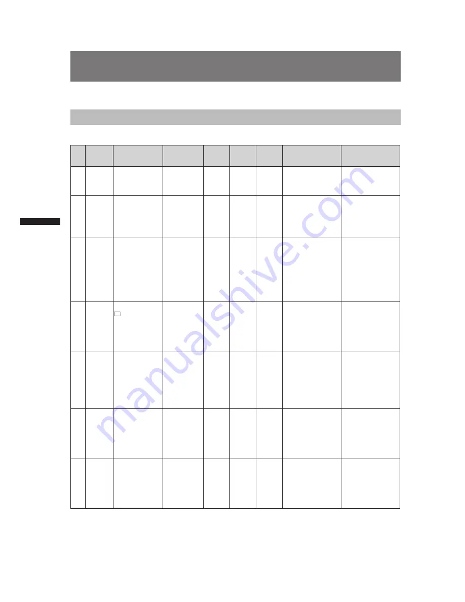
Warning Description Tables

If a problem is detected immediately after the power is turned on, or during operation, this will be indicated by the 
WARNING lamp, lamps inside the viewfinder and a warning tone.

Priority

Warning 

type

LCD or 

viewfinder 

indication

Viewfinder 

LED  

(except tally)

Tally 

lamp

Warning 

lamp

Alarm 

tone *

6

Warning description 

and recording/

playback operation

Countermeasures

1

System 

error

SYSTEM ERROR 
Cause indication *

1


Red blinking

No

Blinks 4 

times per 

second

Blinks 4 

times per 

second

Continuous 

tone

P2 microprocessor 
or control failure. 
Operation stops. 

Check the cause 
indication (*

1

and consult your 
distributor. 

2

Incorrect 

P2 card 

removal

TURN POWER 
OFF 
Blinks red

No

Blinks 4 

times per 

second

Blinks 4 

times per 

second

Continuous 

tone

A P2 card was 
removed during 
access and card data 
was corrupted. 
All four access LEDs 
blink orange (4 Hz) 

Turn off the power. 
Repair the P2 card if 
the clips on the card 
are corrupted. 

3

The 

battery is 

exhauseted

LOW BATTERY 
Red blinking or 
the the last bar 
in battery level 
bar blinks. (This 
indication appears 
also when MENU 
indications have 
been turned OFF.)

No

Blinks 1 

time per 

second

Lights

Continuous 

tone

The battery is 
exhausted.
Recording and 
playback stop. 
The camera stops 
automatically when 
the voltage drops. 

Replace the battery. 

4

P2 card 

fully 

recorded

P2

 FULL

Blinks red 
(appears only for 
3 seconds in MCR 
mode.)

When SAVE 
LED is set to 
P2CARD, the 
SAVE LED 
blinks 4 times 
per second. 

Blinks 4 

times per 

second 

after 

completion 

of 

recording. 

Lights 

after 

completing 

recording

Continuous 

tone after 

completing 

recording

No more space 
on P2 cards left 
for recording.Stop 
recording. *

3

Delete clips that are 
no longer needed or 
insert a new card. 

5

Recording 

error

REC WARNING
Cause indication *

Blinks red

No

Blinks 4 

times per 

second

Blinks 4 

times per 

second

Intermittent 

tone 4 

times per 

second

A recording error 
has occurred. Stop 
recording. *

4

Turn the power off 
and then back on 
again and check 
recording and 
playback. Replace 
any P2 card that does 
not enable normal 
recording. 

6

1394 

connection 

errors

1394INTIAL 
ERROR
Blinks red

No

Blinks 4 

times per 

second 

during 

recording. 

Blinks 4 

times per 

second 

during 

recording. 

No

Incorrect 1394 
connection or signal 
input/output error. 

Check camera and 
external device 
connections and 
reconnect as 
necessary. Then turn 
the power off and 
back on again.

7

PC mode 

1394 

HOST 

connection 

error

No

No

Blinks 4 

times per 

second

Blinks 4 

times per 

second

No

The 1394 cable 
has become 
disconnected or 
multiple devices are 
connected. (Normal 
PC mode operation is 
possible.)

Connect a hard disk 
drive according to 
supplied operating 
instructions. 

Summary of Contents for AGHPX500E - MEMORY CARD CAMERA RECORDER

Page 1: ...s Memory Card Camera Recorder DEUTSCH Für Erlauterungen in Deutsch konsultieren Sie bitte die mitgelieferte CD ROM FRANÇAIS Pour des explications on français veuillez vous reporter au CD ROM fourni ITALIANO Per le istruzioni in italiano vedere il CD ROM in dotazione ESPAÑOL Para la explicacion en español consulte el CD ROM uministrado Model No AG HPX500P Model No AG HPX500E ...

Page 2: ...area is likely to cause harmful interference in which case the user will be required to correct the interference at his own expense Warning To assure continued FCC emission limit compliance the user must use only shielded interface cables when connecting to external units Also any unauthorized changes or modifications to this equipment could void the user s authority to operate it Caution The inter...

Page 3: ...s small chemical waste NETHERLANDS Voor de primaire voeding en het reservegeheugen van het apparaat wordt gebruikgemaakt van een batterij Wanneer de batterij is uitgeput mag u deze niet gewoon weggooien maar dient u deze als klein chemisch afval weg te doen TO REMOVE BATTERY Main Power Battery Ni Cd Ni MH Li ion Battery To detach the battery please proceed in the reverse order of the installation ...

Page 4: ... licensed under the GNU General Public License GPL and GNU Lesser General Public License LGPL and users are hereby informed that they have the right to obtain change and redistribute the source codes of this software Details on GPL and LGPL can be found on the installation CD provided with the unit Refer to the folder called LDOC Details are given in the original English language text To obtain th...

Page 5: ...Using variable frame rates VFR 37 Special Recording Modes 39 Pre recording PRE REC 39 Interval recording INTERVAL REC 39 One shot recording ONE SHOT REC 40 Loop recording LOOP REC 41 Recording Check Function 41 Shot Marker SHOT MARK Recording Function 42 Text Memo Recording Function 42 Normal and Variable Speed Playback 43 Video and recording formats 44 Multiple HD SD formats 44 Selecting recordin...

Page 6: ...emory cards 78 Chapter 5 Preparation Chapter 6 Manipulating Clips with Thumbnails Power Supply 80 Mounting the Battery and Setting the Battery Type 80 Using an AC Power Supply 82 Mounting the Viewfinder and Adjusting its Position 84 Mounting the Viewfinder 84 Adjusting Viewfinder Right Left Position 84 Adjusting Viewfinder Front to Rear Position 85 Diopter Adjustments 85 Screen Adjustments 85 Removing...

Page 7: ...o external devices using the IEEE1394 connector PC mode 122 Procedures for establishing a connection with a PC 122 Procedures for connecting a hard disk 123 Warnings 124 DVCPRO DV Connection via 1394 Connector 125 Recording DVCPRO DV signals input to 1394 connector 125 P2 card recording times 126 Inspections Before Shooting 127 Preparing for Inspections 127 Inspecting the Camera Unit 128 Inspectin...

Page 8: ...adjust the gamma settings for each of the R G and B channels of 1080 60p 50p video and convert to a variety of HD and SD formats P I conversion line conversion and down conversion This produces high quality images in all video formats Multiple HD SD formats The camera supports recording in 20 HD and SD image formats making it ready for news gathering program production film making and other applica...

Page 9: ...mera also features a synchro scan function for capturing screen shots from a computer monitor Scene file dial This dial allows you to instantly retrieve settings that suit shooting conditions Six preset files are provided and you can change the file names and their settings as desired You can also save up to 4 files to an SD memory card and load the files from the card Shooting assist functions User bu...

Page 10: ...lowing recording capabilities in a memory card camera recorder Card selection A card in any slot can be instantly selected switched to in standby mode Recorded content can be quickly passed on to editing or transferred to minimize interruptions in recording making it far more efficient than systems where tapes or disks have to be exchanged Hot swap recording Cards can be replaced during recording A...

Page 11: ...e filled with text on a PC P2 Viewer SD memory card slot The camera provides an SD memory card slot for saving and loading scene files and user settings A metadata upload file created using P2 Viewer containing the name of the person who shot the video the name of the reporter the shooting location or a text memo and other information can be saved to an SD memory card This data file can be loaded as c...

Page 12: ...ing and smooth editing and dubbing Flow of shooting playing and saving The setting values such as the user file are saved to and read from the SD memory card P2 card You can use the following features HD High Definition recording Multi format recording Variable frame rates Slow quick motion recording Maximum 4 channel uncompressed digital audio recording P2 mode shooting and playback Pages XX and ...

Page 13: ...EEE1394 Windows Macintosh Serial Bus Protocol 2 The data file is transferred for nonlinear editing on your computer or other unit The unit directly controls the external hard disk drive and transfers the data file to it The contents can be transferred as a data stream digital dubbing Connecting external devices via the USB connector Page XX Connecting external devices via the IEEE1394 connector Pa...

Page 14: ...hantom 48 V NP 1 type Battery mount V mount type Battery plate Viewfinder AJ VF15BP BE AJ VF20WBP BE AG VF11G Tripod adapter SHAN TM700 Hard carrying case AJ HT901G Rain cover SHAN RC700 Soft carrying case AJ SC900 AG HPX500P E 1 To install a stereo microphone an extra modification is required For more information contact your distributor or designated service provider 2 For the latest information ...

Page 15: ...ccessory can be attached here 6 Shoulder strap fittings The shoulder strap is attached here 7 Lens mount bayonet type The lens is attached here 8 Lens lever Lower this lever to lock the lens to the lens mount 9 Lens mount cap To remove the cap raise the lens lever When the lens is not mounted replace the cap 10 Lens cable microphone cable clamp This clamp secures the lens and microphone cables 11 T...

Page 16: ...ing level control mode for Audio Channels 1 and 2 AUTO Recording level automatically controlled MAN Recording level manually controlled 4 AUDIO LEVEL CH3 CH 4 audio channel 3 4 recording level adjustment controls Set the menu option AUTO LEVEL CH3 AUTO LEVEL CH4 to OFF in the AUDIO SETUP screen to use these controls to adjust the recording level of audio channels 3 and 4 5 AUDIO IN audio input sel...

Page 17: ...supply power to the remote microphone 48V Audio signal from a passive microphone is input The unit supplies power to the remote microphone 8 F AUDIO LEVEL audio recording level adjustment control This control adjusts the recording level of Audio Channels 1 and 2 Level adjustment does not depend on the position of the AUDIO SELECT switch Use the menu options FRONT VR CH1 and FRONT VR CH2 in the AUD...

Page 18: ...nd 4 CH2 4 Audio Channel 2 Audio Channel 4 3 MONITOR ALARM volume control Used to control the volume of sound output from the monitor speakers and earphones It also adjusts the alarm sound volume 4 Speakers The speakers output EE sound during recording and reproduced sound during playback The speakers emit an alarm sound when the warning lamp blinks and or the indicator activates EE sound and play...

Page 19: ...h returns to its original position Each turn of the switch alters the shutter speed For more information see Setting the Electronic Shutter 4 AUTO W B white black BAL switch AWB Automatically adjusts the white balance Set the WHITE BAL switch on the side to A or B and use this switch to adjust the white balance which takes a few seconds The adjusted value is stored in memory Note that auto white b...

Page 20: ...ure the background visible through a window The subject is a high contrast scene 7 WHITE BAL white balance memory selector switch Used to select the white balance adjustment method PRST Use this when you have no time to adjust the white balance The value for the white balance is factory set to 3200 K It can be changed to any color temperature using a menu option For more information see Setting Co...

Page 21: ...21 Chapter 2 Parts and their Functions 31 29 23 28 30 27 16 15 13 17 14 18 12 32 33 25 24 22 20 26 19 21 10 11 ...

Page 22: ...0 connector Connect a USB 2 0 cable to this connector Select USB DEVICE under the menu option PC MODE in the OTHER FUNCTIONS screen to send data via the USB 2 0 connector The camera cannot be used for recording playback or clip operations when this function is used For details see Connecting to External Devices Using USB2 0 Port 22 GENLOCK IN connector This connector inputs a reference signal when...

Page 23: ...een to send data via the 1394 connector For details see Connecting to External Devices Using USB2 0 Port 30 SDI OUT connector This connector outputs SDI signals Use the menu option CMPNT SDI SEL in the setting menu OUTPUT SEL screen to select 720P 1080i 480i or 576i This connector does not support up conversion 31 SCENE FILE dial This dial allows you to load and set the shooting conditions for a s...

Page 24: ...wn in camera mode or MCR mode displays the camera menu or MCR menu Note Use the CURSOR and SET buttons to select thumbnails and access menu functions For details see Manipulating Clips with Thumbnails 4 CURSOR and SET buttons Use these buttons to manipulate menus the menu bar and thumbnails The four triangular buttons are CURSOR buttons and the square center button is the SET button 5 PAGE VAR but...

Page 25: ... to 0 and press the SET button to preset 6 COUNTER counter display selector button The LCD monitor and the viewfinder show the counter value time code user bit and frame rate data depending on how this switch and the TCG switch are set 7 TCG time code selector switch This switch is used to specify the stepping mode for the built in time code generator F RUN Select this position to continuously adva...

Page 26: ...he memory 4 Rear tally lamp When the BACK TALLY switch is set on ON the rear tally lamp behaves in the same way as the back tally lamp 5 Mode LED Shows the camera unit mode CAM Lights in CAMERA mode MCR Lights in MCR mode PC Lights in PC mode 1 LCD monitor The LCD monitor displays the video in the viewfinder Alternatively it can show clips on the P2 card in a thumbnail format In thumbnail display m...

Page 27: ...d output camera signals are not affected 5 CONTRAST control Used to adjust the contrast of the video image in the viewfinder Recorded video and output camera signals are not affected 6 BRIGHT control Used to adjust the brightness of the video image in the viewfinder Recorded video and output camera signals are not affected 7 Front tally lamp This lamp goes on during recording when the TALLY switch i...

Page 28: ...fference Area 00 00 Greenwich 00 30 01 00 Azores Islands 01 30 02 00 Mid Atlantic 02 30 03 00 Buenos Aires 03 30 Newfoundland Island 04 00 Halifax 04 30 05 00 New York 05 30 06 00 Chicago 06 30 07 00 Denver 07 30 08 00 Los Angeles 08 30 09 00 Alaska 09 30 Marquesas Islands 10 00 Hawaii 10 30 11 00 Midway Island 11 30 12 00 Kwajalein 11 30 Norfolk Island 13 00 10 30 Lord Howe Island 12 00 New Zeala...

Page 29: ...to 2007 then press the JOG dial button A year between 2000 to 2030 can be set 9 Turn the JOG dial button to select MONTH then press the JOG dial button 10 Turn the JOG dial button to set MONTH to DEC then press the JOG dial button 11 Set DAY HOUR and MIN in the same way as setting YEAR and MONTH This is a 24 hour clock PUSH MENU TO RETURN 2007 MONTH DECEMBER DAY 25 HOUR 17 MIN 20 YEAR CLOCK SET 12...

Page 30: ...e slide out door to the left The door opens 3 Insert a P2 card in a P2 card slot Press in the card until the eject button pops up 4 Tilt up the popped up EJECT button 5 Insert a P2 card into the AG HPX500P E The P2 CARD ACCESS LED for the appropriate slot indicates the status of the P2 card For how the P2 card status is indicated see P2 CARD ACCESS LED and status of P2 cards P2 Cards The card must...

Page 31: ... rapidly in orange If this is the case turn the power off For more information on warning indications see Warning System Removing a P2 card during access may corrupt clip data Check the clips and restore them if required For more information about how to restore clips see Restoring Clips If a P2 card being formatted is removed it may be not be formatted properly In this case the viewfinder displays...

Page 32: ... enabled Blinks in orange Being accessed Writing or reading being performed Quickly blinks in orange Being recognized The P2 card is being recognised Blinks in green Card full The P2 card has no free space Only reading is enabled Write protected The write protect switch on the P2 card is positioned at PROTECT Only reading is enabled Stays off Card not supported The card is not supported by your AG...

Page 33: ...th a fully charged battery 3 Insert a P2 card and ensure that the P2 CARD ACCESS LED stays on in orange or green Then close the slide out door When more than one P2 card slot contains a P2 card the card in the slot with the lowest number is used first However regardless of slot number a P2 card inserted later will not be accessed until the other cards have been used Example If all four slots contai...

Page 34: ...g menu SW MODE screen to assign functions to the USER MAIN button Shooting White Black Balance Adjustment to Recording Completion For shooting follow the steps below 1 Use the ND FILTER control to select a filter according to light conditions 2 When the white balance is saved Position the WHITE BAL switch to A or B When the white or black balance is not saved and you have no time to adjust the whit...

Page 35: ...EC lamp in the viewfinder stays illuminated 6 To stop recording press the REC START STOP button The REC lamp in the viewfinder goes out Note Operation Buttons In CAMERA mode all operation buttons REW FF PLAY STILL STOP are disabled Normal Recording Pressing the REC START STOP button starts recording of video and sound on the P2 card The video and audio including additional information recorded in on...

Page 36: ...le Frame Rate VFR recording is available only in progressive shooting at 720 vertical lines You can select any of 11 recording frame rates ranging from 12 frames per second fps to 60 fps The list of formats that allow recording by the camera recorder Page XX There may be slight discrepancies between the recording frame rate displayed and the frame rate at which the images are actually recorded Ref...

Page 37: ...hen thumbnails are displayed With the default setting 720P 30P 720P 24P 72P 25P or 720P 50P With any other settings 720P 60P The default setting is 30FRAME at a recording frame rate of 30P and 24FRAME 25FRAME at 25P at a recording frame rate of 24P 4 Press the REC START STOP button Pressing the REC START STOP button starts standard recording in the VFR mode the sound is also recorded Note In the c...

Page 38: ...cts by setting the VFR recording frame rate to 12 fps Recording format REC FORMAT Recording frame rate FRAME RATE 720P 24P 720P 24PN Set to 22 fps or lower 720P 30P 720P 30PN Set to 26 fps or lower 720P 25P 720P 25PN Set to 23 fps or lower One of 11 recording frame rates FRAME RATE can be selected The 720P 24P 720P 30P and 720P 25P formats provide a quick motion effect when processed using a nonli...

Page 39: ...UP screen 3 Press the START STOP button This setting will record audio and video a time period prior to start of recording The following recording modes will disable the pre recording function and start respective recording function when selected Recording of video input via the IEEE1394 connector After a change from playback to recording When changing recording formats During interval recording D...

Page 40: ...hot at each unit of time which has been set 1 Check that the OPERATION TYPE item in the menu option RECORDING SETUP screen and the recording format are set as described below OPERATION TYPE item VIDEO CAM Recording format They are available at 1080i 60i 50i 720P 60P 50P or in SD at 60i 50i 30P 25P 2 Select ONE SHOT in the REC FUNCTION item in the menu option RECORDING SETUP screen 3 Set the time i...

Page 41: ...rn the camera off or select NORMAL in the REC FUNCTION item The following indications appear to the left of the operation status display During recording L REC stays lit During a pause L PAUSE stays lit When remaining memory is low P2 LACK L blinks Note Use a P2 card with at least one minute of remaining recording time Recording of IEEE1394 input is not available The pre recording function is not ...

Page 42: ... not available during loop recording When this function is not available pressing this button displays INVALID Text Memo Recording Function Text memo allows the user to insert a text memo with time code at any point during clip recording and playback This makes it possible to display only the thumbnails of the clips with text memos or to display thumbnails and time codes of the text memo positions...

Page 43: ...ke some time for the camera to read clip information If this is the case the viewfinder displays UPDATING If a P2 card is inserted while another P2 card is being played back the clips on the inserted P2 card will not be played back A P2 card inserted during playback will be recognised after playback ends If you perform variable speed playback on a clip split across more than one P2 card sound may d...

Page 44: ... frames 3 The listed recording times are for four 16 GB P2 cards Using only one 16 GB card will reduce the recording time to 1 4 In addition to the video format and codec function setup and the number of cuts will affect the recording time Selecting recording signals in CAMERA MODE CAMERA MODE allows you to record video shot with the camera Use the setting menus listed below to select recording si...

Page 45: ...tained 480i 576i MCR MODE RECORDING SETUP screen In SD mode 480i 576i you can select DVCPRO50 DVCPRO or DV for recording 1394 connector signals or as playback mode to play back P2 card clips In a change from CAMERA MODE to MCR mode the 480i 576i REC MODE takes over Selecting video output CAMERA MODE and MCR mode allow you to select video output format Use the setting menus listed below to select v...

Page 46: ...480i 525i 59 94i 525i 59 94i 1080i 24PA 24PA over 60i 720P 60P 60P 1 DVCPRO HD 720P 59 94P 4ch 720i 720P 59 94P 1 4ch 720P 59 94P 1 525i 59 94i DVCPRO HD 720P 59 94P 1 720P 30P 30P over 60i 1 1080i 1080i 59 94i 1080i 59 94i 720P 24P 24P over 60i 1 480i 525i 59 94i 525i 59 94i 720P 30PN 30P native recording at 30P capture 2 DVCPRO HD 720P 29 97P 4ch 5 720i 720P 59 94P 1 4ch 5 720P 59 94P 1 525i 59 ...

Page 47: ...i 60i DVCPRO50 DVCPRO25 DV 4625i 50i 4CH or 2CH 6 720P 625i 50i 4ch 6 625i 50i 625i 50i DVCPRO50 DVCPRO25 DV 4 625i 50i 576i 25P 25P over 50i 1080i 576i 1 In FILM CAM mode this means 12P to 60P capture over 60P depending on FRAME RATE menu setting 2 In FILM CAM mode this means 30P native recording at 12P to 60P capture depending on FRAME RATE menu setting 3 In FILM CAM mode this means 24P native r...

Page 48: ...525i 59 94i 4CH or 2CH 7 720P 525i 59 94i 4ch 7 525i 59 94i 525i 59 94i DVCPRO50 DVCPRO25 DV 6 525i 59 94i 1080i 480i SYSTEM FREQ setting menu 50 Hz Format setting Recording status Output setting Output status MCR FORMAT Recording and playback format Recording and playback audio channel CMPNT SDI SEL SDI OUT SDI OUT AUDIO COMPONENT OUT VIDEO OUT Playback of 1394 output 1080i 50i DVCPRO HD 1080i 50...

Page 49: ...iris 5 Turn the AUTO W B BAL switch toward AWB and release it The switch returns to the central position with the white balance automatically adjusted 6 During an adjustment the viewfinder displays the following message AWB Ach ACTIVE To record high quality video with the AG HPX500P E the black and white balances must be adjusted according to conditions For higher quality it is recommended that the...

Page 50: ... adjusted the viewfinder displays an error message If one of the error messages listed below appears take the appropriate steps then adjust the white balance again If the error message appears after repeated readjustments the interior of the unit must be inspected For more information contact your distributor Error message Description Remedies AWB NG The colour temperature is too high Select an app...

Page 51: ...g message ABB ACTIVE Note During adjustment the lens iris automatically becomes CLOSE 4 The adjustment will take effect in a few seconds and the following message will appear ABB END The adjusted value is automatically stored in the memory Notes Ensure that the lens connector is connected and the lens iris is CLOSE During a black balance adjustment light is automatically cut off During a black bal...

Page 52: ...ange of 60 0 Hz to 249 8 Hz 60i Range of 30 0 Hz to 248 8 Hz 30P Used to reduce the effect of horizontal lines when shooting a monitor screen that has a vertical scanning frequency of more than 59 94 Hz Note In any mode the higher the shutter speed the lower the sensitivity of the camera When the iris is automatically adjusted the higher the shutter speed the larger the iris and the shorter the de...

Page 53: ... 1000 1 15 1 30 1 120 1 250 S S 1 60 50 Hz mode Viewfinder displays relating to the shutter See Viewfinder Screen Status Displays Placing the Camera recorder in SYNCHRO SCAN Mode To place the camera recorder in SYNCHRO SCAN mode follow the steps below 1 Press the SHUTTER switch positioned at ON towards SEL to place the camera recorder in SYNCHRO SCAN S S mode 2 In SYNCHRO SCAN mode the speed can be ...

Page 54: ... recording check SPOTLIGHT Assigns auto iris control on off for spotlight BACKLIGHT Assigns auto iris control for backlight compensation BLACKFADE Assigns blackfade WHITEFADE Assigns whitefade GAIN 18dB Assigns a gain increase of 18 dB TEXT MEMO Assigns text memo recording SLOT SEL Assigns P2 card slot selection SHOT MARK Assigns shot marker function LVL METER Assigns channel level indicator funct...

Page 55: ... indications displayed in the window are 1 and 2 Whether to enable or disable the F AUDIO LEVEL control must be preset through menu options FRONT VR CH1 and FRONT VR CH2 Note that this control is factory disabled The menu options are found in the MIC AUDIO1 screen which is accessible from the MAIN OPERATION page 2 Position the AUDIO SELECT CH1 CH2 switch at MAN This AG HPX500P E supports independe...

Page 56: ... AUDIO LEVEL control to adjust the appropriate audio channel so that no excessive audio signals will be admitted Selecting Function for the F AUDIO LEVEL Control The F AUDIO LEVEL control can be assigned the function of adjusting the recording level Use the menu options FRONT VR CH1 and FRONT VR CH2 to determine whether or not to enable control of selected input signals using the F AUDIO LEVEL con...

Page 57: ...g of user settings time date time code and similar values the frame rate data for camera capture external input values via TC IN or 1394 connector input VITC user bits record the frame rate data of camera capture The clip meta data user bit records the user bit values in the subcode area at start of recording Date real time The built in clock calculates the year month day and time from the interna...

Page 58: ...30 30 24 switchable 8 Depends on user bits mode 5 Records VIDEO AUX area user bits input via 1394 regardless of setting 720P 30PN Not related Not recorded Playback 30 frame Not recorded Playback 24 frame Playback 30 Playback locked at 30 Not recorded Not recorded playback frame rate data is converted and generated in synch with video pull down 720P 24PN Not related Not recorded playback 30 frame N...

Page 59: ...ing of input from the 1394 connector in MCR MODE set the setting menu 1394 UB REGEN to ON In slave mode the UB indicator is highlighted In this status the UB MODE setting is disabled A slave relationship once started continues even after input from the TC IN or 1394 connector ends However the following events release a user bit slave status When the setting menu TC IN UB REGEN or 1394 UB REGEN is ...

Page 60: ... code user bits are related as described below Camera capture mode 60i 600 60P 608 30P 308 24P 248 24PA 24C 50i 502 50P 50A 25P 25A XXP XX9 59 94 Hz 720P native XXP XXB 59 94 Hz 720P native Media management data Frame update information Recording start stop mark Verification information on the right hand six digits Fixed value Sequence No 24P 24PA 0 4 Other than above locked at F When 1080i 480i o...

Page 61: ...hifts the target highlighted digit to the left button Increases the highlighted number by one button Decreases the highlighted number by one SET button Use to confirm set time code value 5 Change the position of the TCG switch F RUN steps the time code in free run mode and R RUN set it in recording run mode Notes When 24P or 24PA is used the time code is adjusted every 5 frames Adjust a multiple of...

Page 62: ...n 30P capture at 30PN and other than 25P capture at 25PN 24PN recording at 60P capture Video output 0 1 2 3 22 23 24 25 58 59 60 61 62 63 67 68 Rec start Rec stop Skips Rec start Output time code 00 00 00 00 00 00 00 01 00 11 00 12 00 29 01 00 01 01 02 20 02 20 Recorded video 0 1 2 3 22 23 24 25 58 59 60 61 62 63 67 68 Recorded time code 00 00 00 01 00 02 00 03 00 22 00 23 01 00 01 01 02 10 02 11 ...

Page 63: ...ionship reference time code that conforms to the time code requirements and reference video signals to the TC IN and GENLOCK IN connectors respectively Now the built in time code generator is locked with the reference time code When locked to an external time code generator the time code is at all times locked to the external time code which is displayed as a highlighted value on the counter indic...

Page 64: ...nput a non drop frame time code The time code cannot be externally locked when drop frame mode is selected When the time code is externally locked the video may be distorted but this is because of the 5 frame adjustment and not a malfunction Outputting the time code externally To output time code from the camera s TC OUT connector to a VTR or other recording device in sync with camera picture or p...

Page 65: ...80i 576i SDI OUT 480i 576i SD 480i 576i SDI Disabled 1 VIDEO OUT COMPOSITE Disabled Connection diagram 1 VTR etc TC OUT REF SDI or VIDEO OUT HPX500P E TC HD signal or SD signal TC IN GENLOCK Connection diagram 2 Down conversion SD device REF TC COMPOSITE SDI HPX500P E TC SD signal Delay TC IN GENLOCK Mode Check Screen Displays MODE CHECK button function The viewfinder can display a screen that allo...

Page 66: ...Screen Status Displays 3 BATT battery Lamp This lamp starts blinking a few minutes before the battery charge starts to run out and stays illuminated after the battery is completely flat The battery should be replaced before it is nearly flat so that operation will not be interrupted For more information see Warning System 4 SAVE Lamp This lamp lights when the SAVE switch is set to ON and the LCD is ...

Page 67: ... value cannot be correctly read from 1394 connector input FR Frame rate information for recording FR 60I Standard 60i interlace mode 60 fields sec FR 60P 60P progressive mode 60 frames sec FR 30P 30P progressive mode 30 frames sec FR 24P 24P progressive mode 24 frames sec FR24PA 24p advanced mode 24 frames sec In FR24P and FR24PA modes the last digit indicates the frame conversion sequence informat...

Page 68: ... images recorded in the squeeze mode 7 AWB error LOWLIGHT Appears when the brightness level adjusted by the auto white balance is too low 8 Marker luminance display When markers are displayed the brightness level around the center of the screen is indicated as 0 to 99 99 appears if the percentage is over 99 9 Calendar Month JAN January FEB February MAR March APR April MAY May JUN June JUL July AUG...

Page 69: ...21 AWB operation display The white balance operation is indicated here 22 Displays marker Markers are displayed when the MARKER item in the setting menu DISPLAY SETUP screen is set to ON 23 Scene file name display 24 Media remaining memory display Setting the setting menu P2 CARD REMAIN to ONE CARD displays the remaining time on the P2 card that is currently being recorded and the number of the slo...

Page 70: ...ot be used for special recording modes interval ONE SHOT and loop recording A warning appears when such a P2 card is inserted in a P2 device or when recording is completed RUN DOWN CARD Indicates that a P2 card has reached the end of its life Replace any card that causes this warning to appear The card can still be recorded and played back but the warning appears when it is inserted in a P2 device...

Page 71: ...ried out again replace the card with another one ERROR Other type of trouble 1394 This is displayed when trouble has occurred in the 1394 connections or signals P2 mode only 1394 INITIAL ERROR Connection error 1394 INPUT ERROR Input error 1394 INPUT ERROR OTHER FORMAT Wrong input format LOW BATTERY Indicates that the battery is exhausted Camera status display ABW ABW indicator ABB ABB indicator AW...

Page 72: ...ter speed display 12 Audio level meter display 13 IRIS display 14 Zoom position display 15 Auto IRIS control display 16 Media remaining memory display 18 Recommended ND filter display 19 ND filter display 20 Gain display 2 21 AWB information display 3 23 Scene file name DUB display 24 Media data display 25 Operating status display 26 Remaining media display 27 Special recording display 28 Safety zone...

Page 73: ...HER DISPLAY DISPLAY SETUP MENU BACK PARTIAL LCD CONTRAST Notes When closing the LCD monitor make sure that it is shut tight In an environment with sudden temperature changes condensation may form on the liquid crystal surface of the monitor If this happens wipe off the moisture with a soft dry cloth When the camera recorder is very cold the video image in the LCD monitor will appear slightly darke...

Page 74: ... F6 Default value F1 Current value SCENE FILE current operating status values F2 Current value F3 Current value F4 Current value F5 Current value F6 Current value F1 Saved value SCENE FILE Saved camera values F1 F2 F3 F4 F5 F6 SCENE FILE 1 F1 F2 F3 F4 F5 F6 SCENE FILE 2 F1 F2 F3 F4 F5 F6 SCENE FILE 3 F1 F2 F3 F4 F5 F6 SCENE FILE 4 USER FILE1 USER FILE2 USER FILE3 USER FILE4 USER FILE initial value...

Page 75: ...old of the SD memory card and remove it Close the lid SD memory cards must not be used or stored in an environment where they may be Exposed to high temperatures humidities Exposed to water droplets or Electrically charged For storage the SD memory card must be kept inserted into the AG HPX500P E with the lid closed Formatting Writing and Reading an SD memory card Open the CARD FUNCTIONS screen fr...

Page 76: ...ged To change these settings set the camera recorder to recording standby state Factory setting F1 SCENE File suitable for normal shooting F2 SCENE FLUO File suitable for shooting under fluorescent lights ie indoors F3 SCENE SPARK File suitable for shooting with fuller variations of resolution coloring and contrast F4 SCENE B STR File for broadening the contrast of dark parts such as when shooting ...

Page 77: ... REW NAME EDIT PUSH SW POSITION F2 FLU0 6 After you finish setting the filename press the MENU button This completes the NAME EDIT change A change that has been confirmed is retained after a power down and is not affected by dial position Example2 Save the F1 scene file to the camera 1 Turn the JOG dial button to move the cursor to the option LOAD SAVE INT Then press the JOG dial button OPERATION TYPE...

Page 78: ...ngs are automatically saved in the unit and the saved data is written on an SD memory card When data has been read from an SD memory card the current settings are rewritten at the same time as the data saved inside the unit The data in all the scene files F1 to F6 is rewritten If you have saved a scene file 1 Set the unit s POWER switch to ON 2 Select SCENE FILE on the setting menu CARD FUNCTIONS sc...

Page 79: ... To title a file 1 Perform steps 1 to 4 2 Use the JOG dial button to select characters then press the JOG dial button to move to the next character You can input any of the following characters Space A to Z 0 to 9 _ You can erase all characters using the RESET button 3 After entering all the characters press the cursor button at the left end of the characters and then press the JOG dial button Note...

Page 80: ...ck with the battery charger before using it Please refer to the battery charger s instruction manual for information about charging Mounting the Battery and Setting the Battery Type Using an Anton Bauer Battery Pack 1 Power supply output connector for lighting Note The Anton Bauer battery holder includes both a power supply output connector for lighting and a lighting control switch which are conv...

Page 81: ...e information The following Anton Bauer batteries can be used PROPAC14 TRIMPAC14 HYTRON50 HYTRON100 HYTRON140 DIONIC90 DIONIC160 Using an NP 1 type battery pack When replacing the battery holder consult your distributor 1 Remove the battery holder 2 Mount the NP 1 type battery case on the camera recorder Tighten the mounting screws Tighten the power contact screws Insert the upper part of the remo...

Page 82: ... For information about the V mount adapter plate please contact the store where you purchased the camera recorder Using an AC Power Supply 1 Plug the DC OUT connector into the camera recorder s external DC input socket DC IN Socket AC Adapter 2 Turn the AC adapter power ON If the AC adapter is equipped with a power switch 3 Turn the camera recorder power switch ON At power on a rush current occurs...

Page 83: ...apter power before turning ON the camera recorder s power switch If this sequence is reversed the camera recorder may malfunction due to slow rising of the AC adapter output voltage To connect a battery to the DC IN connector select BATTERY in the EXT DC INSEL item and select the battery type in the BATTERY SELECT item Select the EXT DC IN SEL or BATTERY SELECT from the BATTERY SETUP screen Note t...

Page 84: ...rew counterclockwise to cancel the safety mechanism and slide the viewfinder in the direction of the arrow 5 Turn the viewfinder securing screw clockwise to prevent it from falling off 6 Tighten the viewfinder right left positioning rings Note Be sure to firmly tighten the viewfinder securing screw on the viewfinder right left positioning module The viewfinder may fall off if the viewfinder securing screw...

Page 85: ...r 2 Turn the diopter adjusting ring until you get the sharpest possible image in the viewfinder Screen Adjustments Use the following controls to adjust viewfinder screen Brightness Turn the BRIGHT control Contrast Turn the CONTRAST control Peaking Turn the PEAKING control 1 Turn on the POWER switch on the camera 2 Set the OUTPUT switch of the camera to BARS 3 Turn the viewfinder BRIGHT and CONTRAST c...

Page 86: ...he POWER switch is turned off 2 Loosen the viewfinder right left positioning rings 3 Turn the viewfinder securing screw counterclockwise slide the viewfinder in the direction of the arrow and remove it 4 Disconnect the viewfinder cable and microphone clamp from the clamp and remove them Loosen Viewfinder securing screw ...

Page 87: ...gn the indentation at the top center of the lens mount with the center mark of the lens 3 Lower the lens clamping lever to clamp the lens 4 Secure the cable through the cable clamp and plug it into the LENS connector 5 Adjust the lens flange back Notes Please refer to the lens instruction manual for guidance on lens handling When the lens is removed install the mount cap to protect the device Mount...

Page 88: ...al and fully open the iris 3 Place the flange back adjustment chart about 3 m from the lens and adjust the lighting on the chart to obtain an appropriate video output level If the video level is too high use the filters or the shutter 4 Loosen the F f Flange focus ring clamping screw Note F b Flange back may be indicated on some lenses 5 Set the zoom ring to the telephoto position either manually or...

Page 89: ...The AJ MC700P microphone kit optional includes a microphone that can be mounted on the camera 1 Open the microphone holder 2 Mount the microphone and tighten the clamping screw 3 Connect the microphone cable to the MIC IN jack on the camera 4 Set the AUDIO IN switch to FRONT depending on the audio channel to be recorded MIC IN Jack Microphone holder Viewfinder Clamping Screw AUDIO IN Switch ...

Page 90: ... 1 Connect the audio device to the AUDIO IN jack with the XLR cable 2 Set the AUDIO IN switch to REAR for the channel to which the XLR cable is connected 3 Set the LINE MIC 48V selector switch on the rear panel to LINE AUDIO IN Switch AUDIO IN Jack LINE MIC 48V Selector Switch ...

Page 91: ...screw 2 Mount the camera on the tripod adapter Slide the camera forward along the grooves until you hear a click Removing the Camera from the Tripod Adapter While holding the red lever down move the black lever in the direction of the arrow and slide the camera backward to remove it Note If the tripod adapter pin does not return to its original position after the camera has been removed hold the r...

Page 92: ...k Tighten the cord Secure with the surface fastener Secure with the surface fastener Attaching the F AUDIO LEVEL Control Knob If you use the F AUDIO LEVEL control frequently attach the accessory knob so that it can be easily operated Remove the screw in the center of the F AUDIO LEVEL control and attach the accessory knob using the screw included When attaching the knob be sure to align the marks ...

Page 93: ... setting values cannot be written to an SD memory card However the menu settings performed using the AJ RC10G can be written to an SD memory card Next time the AJ RC10G is connected the setting values will return to the AJ RC10G settings ECU DATA SAVE can be selected from the SW MODE screen on the CAM OPERATION page If ECU DATA SAVE is set to ON the values adjusted or set using the AJ RC10G are re...

Page 94: ...ack delete and repair clips Add or delete a shot mark on the clip thumbnail Format P2 cards and SD memory cards Upload the clip meta data from an SD memory card Thumbnail Operations Thumbnail Overview Thumbnail screens are configured as follows PROPERTY CLIP PROPERTY EXIT CARD STATUS DEVICES PROPERTY SETUP SYSTEM INFO META DATA LOAD EXIT RECORD USER CLIP NAME INITIALIZE PROPERTY OPERATION DELETE EX...

Page 95: ...u items are displayed When EXIT is selected and the SET button is pressed the menu display is cleared and the original screen is restored 6 Recording mode format display This is where the recording mode and format of the recorded images are displayed 7 Indicators M Shot mark This indicates that a clip has a shot mark W Wide This indicates that a clip has been recorded in the 16 9 aspect ratio wide...

Page 96: ...LL CLIP Display all clips SAME FORMAT CLIPS The clips in the same recording format are displayed SELECTED CLIPS Display randomly selected clips MARKED CLIPS Display clips with shot marks attached TEXT MEMO CLIPS Clips with text memos are displayed Thumbnails at text memo positions time codes TC total number of memos and the current order of the clips are displayed SLOT CLIPS Display clips recorded...

Page 97: ...proxy indicator between indication and no indication ON OFF The factory setting is ON indication DATA DISPLAY The time display field of the clip offers a choice of Time Code TC User Bits UB Shooting Time TIME or Shooting Date DATE Shooting Time and Date DATE TIME The factory setting is Time Code DATE FORMAT You can specify the display order for the shooting date as either Year Month Day YMD Month D...

Page 98: ... a pause pressing the REW button moves the pause position to the beginning of the clip Pressing the REW button again moves the pause position to the beginning of the previous clip During a pause pressing the FF button moves the pause position to the beginning of the next clip 6 Pressing the STOP button during clip playback stops the playback and returns the display to the thumbnail screen Note Whe...

Page 99: ... SET button stops the deletion operation in the middle Restoring Clips Restores clips that are defective as a result of sudden poweringdown during recording or removal of the P2 card being accessed Note Only those clips with yellow corrupt clip markers can be restored Delete the clips with red corrupt clip markers If the clip cannot be deleted format the P2 card During restoration of the clips how...

Page 100: ...panasonic biz sav p2 Regarding SD memory cards to be used see Cautions in using SD memory cards Note The file which was edited by except P2 viewer is displayed as UNKNOWN DATA and may not be read You can set the underlined items by loading the metadata upload file on the SD memory card All other items are automatically set during shooting GLOBAL CLIP ID Displays the global clip ID which indicates th...

Page 101: ...ead in Uploaded data If no clip metadata has been read in or if the setting for recording clip metadata has been turned off Same as GLOBAL CLIP ID UMID data TYPE2 USER CLIP NAME to be recorded If clip metadata has been read in Uploaded data COUNT value If no clip metadata has been read in or if the setting for recording clip metadata has been turned off Same as CLIP NAME The COUNT value is indicat...

Page 102: ...ing start REC PAUSE recording pause Clip 1 COUNT value 0003 Clip 2 COUNT value 0004 1st card 2nd card If the clip thumbnails are displayed as shown in the example above or their properties are indicated using a P2 device the thumbnail and COUNT value of clip 1 will be displayed Clear the uploaded metadata Select META DATA INITIALIZE and press the SET button Select YES when the confirmation screen i...

Page 103: ...e card 5 The selected P2 card is formatted Formatting SD memory cards SD memory cards can also be formatted from the thumbnail screen With an SD memory card inserted into the camerarecorder perform the following operation 1 Press the MODE button to enter the MCR mode The thumbnail screen appears on the LCD monitor 2 Press the thumbnail menu button to open the menu 3 Select OPERATION FORMAT The fol...

Page 104: ...E item on the SCENE FILE screen other than the default during 720P 24PN or 720P 30PN recording operation 5 Clip metadata The video and audio formats videographer information and other detailed data are displayed here Use the CURSOR button to select the item and press the SET button For details on the clip metadata see Setting of Clip Meta Data P2 Card Status Display P2 Card Status Display Settings...

Page 105: ...in minute is displayed 4 Total remaining free space for the slot Displays the total remaining free space for all 4 slots Please note that the remaining capacity of a write protected P2 card is not included in the total remaining capacity When USED is selected 1 3 4 2 1 Write protect Mark The mark appears if the P2 card is write protected 2 P2 Card Status used memory capacity The used memory capaci...

Page 106: ...ance with the SD standard SUPPORTED NOT SUPPORTED USED Space used BLANK Space available TOTAL Total space NUMBER OF CLIPS Number of clips PROTECT This indicates that the SD memory card is write protected Confirmation of Metadata Upload The contents of the metadata upload file that is read from the SD memory card can be checked Select META DATA PROPERTY The following screen appears For more informati...

Page 107: ... mode press the MENU button The function screen appears in the viewfinder and on the LCD screen PUSH MENU TO RETURN 2 CAMERA SETUP 3 SW MODE 4 RECORDING SETUP 5 AUDIO SETUP 6 OUTPUT SEL 7 DISPLAY SETUP 8 BATTERY SETUP CAMERA MENU 1 SCENE FILE 2 Use the JOG dial button or the Up and Down cursor buttons to highlight the function you want to change PUSH MENU TO RETURN 2 CAMERA SETUP 3 SW MODE 4 RECORD...

Page 108: ... change other functions repeat steps 2 to 5 To exit the function screen and return to the normal screen press the MENU button again Initializing the menu settings The menu settings contain both the user file settings and the scene file settings You can initialize them separately To initialize the user file i e all the settings other than the scene file settings Select INITIAL in USER FILE of the OTHER...

Page 109: ...ASPECT CONV CAMERA SETUP A IRIS LEVEL REC FORMAT RECORDING SETUP MARKER LIMITER CH3 SAFETY ZONE LIMITER CH4 DATE TIME AUTO LEVEL CH3 LEVEL METER AUTO LEVEL CH4 ZOOM 25M REC CH SEL FRONT VR CH2 LIMITER CH1 CARD BATT TEST TONE P2CARD REMAIN F MIC POWER1 OTHER DISPLAY F MIC POWER2 LCD BACKLIGHT R MIC POWER LCD SET F MIC CH1 LEVEL SELF SHOOT F MIC CH2 LEVEL DOWNCON MODE R MIC CH1 LEVEL DISPLAY ASPECT ...

Page 110: ...G L95 NEAR USER FILE OTHER FUNCTIONS FILTER EXTENDER WHITE SHUTTER GAIN VF LED GL PHASE H PHASE SYSTEM FREQ MCR mode menu RECORDING SETUP MCR FORMAT 480i 576i MCR MODE 1394 UB REGEN UB MODE 1394 TC REGEN TC MODE OTHER FUNCTIONS USER FILE CLOCK SET ACCESS LED SAVE LED TIME ZONE SYSTEM FREQ LANGUAGE OUTPUT SEL CMPNT SDI SEL SDI METADATA SDI EDH DISPLAY SETUP LEVEL METER DATE TIME CARD BATT OTHER DIS...

Page 111: ...OPERATION TYPE option setting 60P 60i 1 60 0 1 249 8 30P 30PN 1 30 1 1 48 0 1 249 8 24P 24PA 24PN 1 24 0 1 48 0 1 249 8 When FILM CAM is selected as the OPERATION TYPE option setting The shutter speed is displayed as an angle such as 180 0d 10 0 deg 180 0 deg 350 0 deg the angle can be changed in increments of 0 5 degrees DETAIL LEVEL Adjusts the level of the image outline correction in the horizo...

Page 112: ...RM1 Suitable for shooting in the open air or under a halogen lamp NORM2 Suitable for brighter colors than the NORM1 mode FLUO Suitable for shooting under fluorescent light indoors CINE LIKE Suitable for cinema like image SKIN TONE DTL Sets the skin tone details Select ON to reduce the skin tone details and soften the skin tone ON OFF V DETAIL FREQ Sets the vertical detail for shooting in 480 24P 24...

Page 113: ... value to 18 dB This setting takes effect with the 60i and 60P recording formats only It is not valid when the recording frame rate is less than 22 fps or when the slow shutter mode 1 15 is established When the gain value is set to 18 dB or set from 18 dB to another value the image can be disordered for a moment If the unit is being used in the MANUAL mode or AUTO mode set the AGC item on the AUTO...

Page 114: ...F Uses the non drop frame mode The non drop frame mode is used when a frame rate of 24P 24PA or 24PN is selected in a recording format regardless of TC MODE setting TC IN UB REGEN Selects the user bits to be recorded when recording signals from a device connected to the TC IN connector ON Records the user bits of the signal input to the TC IN connector OFF Records the user bits selected in the men...

Page 115: ...l OFF Enables dial control of CH3 level via dial AUTO LEVEL CH4 Selects the method for selecting CH4 level ON Automatically controls CH4 level OFF Enables dial control of CH4 level via dial 25M REC CH SEL Selects the audio channels to be recorded in the DVCPRO and DV formats 2CH Only recorded on CH1 and CH2 4CH Recorded on channels 1 to 4 TEST TONE Selects the test signal OFF Disables test tone ou...

Page 116: ...to Z99 CARD BATT Turns on and off card and battery remaining level ON OFF P2CARD REMAIN Switches the indication of remaining P2 memory card capacity TOTAL Indicates total remaining capacity of all cards ONE CARD Indicates the remaining capacity of the card that is being recorded OTHER DISPLAY Select how much information to display on the screen OFF PARTIAL ALL LCD BACKLIGHT Adjusts the backlight o...

Page 117: ...Sets near end voltage for DIONIC90 Adjustable in 0 1 V units DIONIC160 NEAR Sets near end voltage for DIONIC160 Adjustable in 0 1 V units NP L7 NEAR Sets near end voltage for NP L7 Adjustable in 0 1 V units ENDURA7 NEAR Sets near end voltage for ENDURA7 Adjustable in 0 1 V units ENDURA10 NEAR Sets near end voltage for ENDURA10 Adjustable in 0 1 V units ENDURA D NEAR Sets near end voltage for ENDUR...

Page 118: ...ts one of the following shading compensation parameters DEFAULT Standard lens setting USER1 User setting 1 USER2 User setting 2 USER3 User setting 3 OFF Sets shading compensation to OFF SHADING USER Selects whether to set shading parameters to SHADING SELECT USER1 2 and 3 or not Off YES On This item is disabled when SHADING SELECT is set to DEFAULT or OFF CAC PROPERTY Selects whether to indicate t...

Page 119: ...he START STOP button works for the backup unit REC_P This switches between recording and pause STOP This switches between recording and stop If the backup unit does not have a rec pause function select STOP PC MODE Selects the terminal for data transfer You cannot select USB and 1394 at the same time USB DEVICE Mode for sending files using the USB connector 1394 DEVICE Mode for sending files using t...

Page 120: ...WHITE Sets the conditions white balance value for lighting the symbol LED in the viewfinder PRE Preset OFF Off SHUTTER Sets the conditions shutter status for lighting the symbol LED in the viewfinder ON OFF FILTER Sets the conditions filter status for lighting the symbol LED in the viewfinder NG Abnormal No1 No1 w o No1 other than No 1 OFF Off EXTENDER Sets the conditions extender status for lighting ...

Page 121: ...Press the setting menu button to end menu operations 4 Press the MODE button to turn on the MCR mode LED and keep the button held down This lights the PC mode LED indicating that the unit is in the PC mode 5 Edit data on the PC For details refer to the Operating Instructions supplied with the PC When you establish the USB connection for the first time install the accessory P2 software for AG HPX500...

Page 122: ...F SAVE USER FILE 3 Press the setting menu button to end menu operations 4 Press the MODE button to turn on the MCR mode LED and keep the button held down This lights the PC mode LED indicating that the unit is in the PC mode 5 Edit data on the PC For details refer to the Operating Instructions supplied with the PC When using an IEEE1394 connection for the first time first install the P2 software on ...

Page 123: ...witch OFF when copying completes Note Data cannot be copied from the hard disk to a P2 card Use hard disks under the following conditions Use a separate power supply not the 1394 bus to power the hard disk since this unit cannot supply power Format the hard disk for this unit Operate hard disks within its operating specifications temperature etc Do not use hard disks in locations that are unstable ...

Page 124: ...d TOO MANY TARGETS There are too may 1394 connections CANNOT ACCESS TARGET The connected device cannot be accessed CANNOT ACCESS CARD The card cannot be accessed MISMATCH COMPONENT There is a mismatch with the connected device UNKNOWN DEVICE CONNECTED A device other than a hard disk is connected P2 CARD IS UNFORMATTED The P2 card has not been formatted CARD IS EMPTY CANNOT COPY There is no data on...

Page 125: ...om the TC OUT connector is not synchronized to the video signal output from the MON OUT connector DVCPRO DV Connection via 1394 Connector Subcode area time codes and user bits When input from the IEEE1394 interface is selected and the TCG switch is set to F RUN and F RUN TC SAVE is set to 1394 the time code of the subcode area input from the 1394 connector can be recorded on a P2 card To record us...

Page 126: ...e thumbnail screen as this will prevent normal operation of the application software Unprocessed video and audio signals are output via the IEEE 1394 interface during special playback When monitored on another device these video and audio signals may sound different than when played back on this unit CH1 and CH2 audio channel signals for the DV or DVCPRO 25M format are output via the IEEE1394 inte...

Page 127: ...2 card access LEDs light up in green when P2 cards are inserted If the access LED for the P2 card slot in which a P2 card is inserted keeps blinking in green or if there is no display recording is not possible on that particular P2 card 1 2 3 4 Make sure you check that the system is operating normally before embarking on a shoot We recommend using a colour video monitor to check the image Preparin...

Page 128: ...creen changes according to the switch setting 7 When a lens with an extender is mounted set the extender to the operating position to check that the extender operates properly Inspecting the Memory Recording Functions Make sure you successively carry out the inspections from Inspecting the P2 Card Recording to Inspecting the Earphone and Speaker Inspecting the P2 Card Recording 1 Check on the disp...

Page 129: ...the AUDIO LEVEL CH3 CH4 controls clockwise to check that the level indication increases Inspecting the Earphone and Speaker 1 Turn the MONITOR control to check that the speaker volume changes 2 Connect an earphone to the PHONES jack Check that the speaker is turned off and the microphone sound can be heard from the earphone 3 Turn the MONITOR control to check that the earphone volume changes Inspe...

Page 130: ...splay number changes as recording progresses 5 Press the REC START STOP button again Check that recording stops and the counter display number stops changing 6 Set the TCG switch to F RUN Check that the counter display number changes regardless of recording status 7 Hold down the DISP MODE CHECK button to check the date and time on the LCD monitor or in the viewfinder Adjust the date and time setti...

Page 131: ...licks into place to close the eyepiece Note When outdoors never carry or set up the camera with the eyepiece facing up to prevent sunlight which could damage the internal parts of the eyepiece Phenomenon Inherent to CCD Cameras Smears Smears may appear when shooting an object with very high brightness This phenomenon may appear more frequently as the electronic shutter speed increases Charging the...

Page 132: ...exhausted Recording and playback stop The camera stops automatically when the voltage drops Replace the battery 4 P2 card fully recorded P2 FULL Blinks red appears only for 3 seconds in MCR mode When SAVE LED is set to P2CARD the SAVE LED blinks 4 times per second Blinks 4 times per second after completion of recording Lights after completing recording Continuous tone after completing recording No...

Page 133: ...arning appears only during recording Replace or insert additional P2 cards 1 P2 SYSTEM ERROR cause indication P2 MICON ERROR The P2 microprocessor does not respond P2 CONTROL ERROR A P2 recording error has occurred REC RAM OVERFLOW Overflow of recording RAM 2 REC WARNING causes CARD ERROR P2CARD error indicates the number of the slot of the card with the error ERROR Other recording errors 3 In a tr...

Page 134: ...nu Then access the site listed above to download a driver if necessary Place the downloaded file on an SD memory card and load the driver into the camera For detailed information on the update procedure visit the above site Be sure to power the camera from an AC adapter during the installation The camera uses only SD memory cards that comply with the SD specifications Be sure to format SD memory car...

Page 135: ...135 Dimensions and specifications Chapter 10 Specifications Chapter10 Specifications Dimensions and specifications Dimensions 261mm 140mm 318mm ...

Page 136: ... mode gain fixed at 0 dB 30p 24p 24pA mode 0 3 6 9 12 dB In slow shutter mode gain fixed at 0 dB Shutter speed preset 60i 60p mode 1 60 OFF 1 100 1 120 1 250 1 500 1 1000 1 2000 sec 30p mode 1 30 1 50 OFF 1 60 1 120 1 250 1 500 1 1000 sec 24p 24pA mode 1 24 1 50 OFF 1 60 1 120 1 250 1 500 1 1000 sec 50i 50p mode 1 50 OFF 1 60 1 120 1 250 1 500 1 1000 1 2000 sec 25p mode 1 25 1 50 OFF 1 60 1 120 1 25...

Page 137: ...2 card The recording time may be shorter depending on the number of shots recorded HD video system Sampling frequency Y 74 25 MHz Pb Pr 37 125 MHz Quantizing 8 bits Video compression system DCT variable length code Video compression rate 1 6 7 Video recording bit rate 100 Mbps Audio system Sampling frequency 48 kHz Quantizing 16 bits 4 CH Head room 20 dB Video Input Output GEN LOCK IN BNC 1 Y 1 0 ...

Page 138: ...iant with IEEE 1394 DC IN XLR 1 4 pins DC 12 V 11 0 V to 17 0 V DC OUT 4 pins DC 12 V 11 0 V to 17 0 V max 1 5 A REMOTE 10 pins LENS 12 pins EVF 20 pins USB2 0 DEVICE Type B 4 pins compliant with USB ver 2 0 LCD Monitor Accessories LCD monitor 3 5 inch LCD color monitor 210 000 pixels 4 3 Accessories 1 5 inch view finder 4 3 CRT NTSC PAL switchable Shoulder strap Operating instructions P2 Software ...

Page 139: ... 1 GND 2 AUDIO IN H 3 AUDIO IN C Panasonic Part No K1AB103A0007 Manufacturer Part No HA16PRM 3SG Hirose Electric Co PUSH 1 3 2 Connector signal description AUDIO OUT 1 GND 2 L CH OUT H 3 L CH OUT C 4 R CH OUT H 5 R CH OUT C Panasonic Part No K1AA105H0016 Manufacturer Part No HA16RD 5P Hirose Electric Co 2 3 1 4 5 ECU 1 CAM CONT 2 CAM DATA 3 NC 4 ECU ON 5 UNREG 12V 6 GND Panasonic Part No K1AY106J0...

Page 140: ...ther Countries outside the European Union This symbol is only valid in the European Union If you wish to discard this product please contact your local authorities or dealer and ask for the correct method of disposal PANASONIC BROADCAST TELEVISION SYSTEMS COMPANY UNIT COMPANY OF PANASONIC CORPORATION OF NORTH AMERICA Executive Office One Panasonic Way 4E 7 Secaucus NJ 07094 201 348 7000 EASTERN ZON...

Reviews: