Panasonic AGDVC200 - DV CAMCORDER Operating Instructions Manual Download Page 35

35

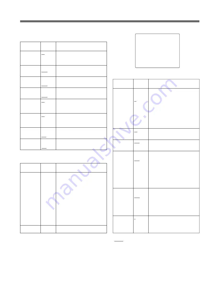
MAIN menu 2 of 2 (main menu)

#

NEXT

¢¢¢¢ 

MAIN 2/2 

¢¢¢¢

MARKER/ZEBRA..
VF DISPLAY 1/2..
VF DISPLAY 2/2..
! LED..
GENLOCK..
CAMERA ID..
TIME/DATE..
DIAGNOSTIC..

MARKER/ZEBRA

Item

Setting

options

Remarks

SAFETY ZONE

OFF
01

:

06

:

09

For  selecting  the  shape  of  the  safety
markers.
OFF: No markers are displayed.
01:

80% and 90% corner display

02:

80% corner display

03:

90% corner display

04:

80% and 90% box display

05:

80% box display

06:

90% box display

07:

16:9 picture frame and 90% of 16:9 display

08:

16:9 picture frame and 80% of 16:9 display

09:

16:9 picture frame (100%) display

ZEBRA2

ON
OFF
SPOT

For selecting the zebra 2 pattern type.
ON:

Zebra  patterns  1  and  2  are
displayed.

OFF: Only zebra pattern 1 is displayed.
SPOT: Zebra  pattern  1  is  displayed  from

the  level  set  for  ZEBRA1  DETECT
to  the  level  set  for  ZEBRA2
DETECT.

VF DTL

1
2
3
OFF

For selecting VF DTL.
The higher the number, the more the detail
of  the  signals  for  the  viewfinder  is
emphasized.    When  OFF  is  set,  the  detail
signals are not output.

CENTER MARK

ON
OFF

For setting the center marker display to ON
or OFF.
ON: Displayed

OFF: Not displayed

ZEBRA1 DETECT

070%

:

104%

For setting the boundary at which the zebra
1 pattern appears.

ZEBRA2 DETECT

071%

:

085%

:

105%

When  the  next  menu  item,  ZEBRA2,  is  set
to SPOT or OFF:

>

This item sets the boundary at which the
zebra 1 pattern appears.

When  the  next  menu  item,  ZEBRA2,  is  set
to ON:

>

This  item  sets  the  boundary  level  at
which the pattern is switched to zebra 1.

<Note>
The  ZEBRA2  DETECT  level  must  be  set
higher than the ZEBRA1 DETECT level.

Menu contents

MAIN menu 1 of 2 (main menu)

LENS SHADING

Item

Setting

options

Remarks

SHADING (USER)

For  performing  shading  compensation  for
the USER lens.

MIC/AUDIO

Item

Setting

options

Remarks

FRONT MIC
POWER

ON
OFF

ON: Phantom  power  is  supplied  to  the

front microphone.

OFF: Phantom  power  is  not  supplied  to  the

front microphone.

LINE CH2

+4dB
0dB
–6dB

For selecting the rear jack AUDIO CH2 line
input level.

FRONT MIC

–40dB
–50dB
–60dB

For selecting the camera mic input level.

REAR MIC CH2

–40dB
–50dB
–60dB

For  setting  the  input  mic  level  for  the  rear
jack AUDIO CH2 input.

MIC LOWCUT CH1

ON
OFF

ON: The  low-cut  filter  is  set  to  ON  for  the

CH1 mic input.

OFF: The low-cut filter is set to OFF for the

CH1 mic input.

MIC LOWCUT CH2

ON
OFF

ON: The  low-cut  filter  is  set  to  ON  for  the

CH2 mic input.

OFF: The low-cut filter is set to OFF for the

CH2 mic input.

LINE CH1

+4dB
0dB
–6dB

For selecting the rear jack AUDIO CH1 line
input level.

LENS SELECTA

B
C
USER

For  selecting  the  type  of  lens  mounted  on
the unit.
A:

S18 

k

6.7BERM4

S18 

k

6.7BRM4

S19 

k

6.5BERM4

S19 

k

6.5BRM4

YH18 

k

6.7IRS

YH12 

k

4.8IRS

B:

YH18 

k

6.7KRS

YH14 

k

7.3KRS

YH12 

k

4.8KRS

S14 

k

7.5BRM4

S17 

k

6.6BRM4

C:

S14 

k

7.3BRM

(For AG-DVC200L)

USER:Lens other than A, B or C

REAR MIC CH1

–40dB
–50dB
–60dB

For  setting  the  input  mic  level  for  the  rear
jack AUDIO CH1 input.

” indicates the factory setting.

Summary of Contents for AGDVC200 - DV CAMCORDER

Page 1: ...Before attempting to connect operate or adjust this product please read these instructions completely AG P F0301T2051 Printed in Japan VQT9277 2 P Digital Video Camera Recorder NTSC...

Page 2: ...RSONNEL FCC Note This device complies with Part 15 of the FCC Rules To assure continued compliance follow the attached installation instructions and do not make any unauthorized modifications This equ...

Page 3: ...tings 22 Setting the user s bit 22 Setting the time code 22 Scene files 23 Scene file function 23 Scene file setting method 23 Editing scene filenames Example USER files 23 Returning a scene filename...

Page 4: ...ngs Auto iris mode selection function This enables three auto iris settings to be selected The settings can easily be switched to match the shooting conditions Menu jog dial system A jog dial button e...

Page 5: ...90 BP L60 L90 NP 1B 1 5 viewfinder AJ VF10 AJ VF15 Digital Video Camera Recorder AG DVC200 Note Checking the lens shading compensation This unit comes with a function which provides shading compensati...

Page 6: ...his position than at the STBY position so that the battery will supply power to the unit for a longer period of time Compared with the STBY position more time is taken to start recording after the VTR...

Page 7: ...speaker When an earphone is connected to the PHONE jack the sound of the speaker will be automatically cut off What can be monitored is the mixed sound of CH1 and CH2 7 MONITOR volume control This is...

Page 8: ...of the lens is connected to this jack For further details on the lenses that can be used refer to the operating instructions of the lenses concerned 8 MIC IN mic input jack XLR 3 pin The accessory mi...

Page 9: ...refer to Using the unit with external components page 29 1 2 3 4 6 7 5 6 5 1 EJECT REW FF STOP PLAY PAUSE 9 8 8 REW rewind FF fast forward buttons lamps When one of these buttons is pressed in the sto...

Page 10: ......

Page 11: ...BATTERY on the sub menu screen Select NiCd12 if the NP 1B is to be used See page 34 Reference To remove the battery pack slide it in the opposite direction to the one in which it was attached while k...

Page 12: ...power 5 Proceed with the flange back adjustment for the lens 3 Set the unit s POWER switch to ON When an AC adapter other than the AJ B75 is to be used check the pin signals of the external DC input s...

Page 13: ...d attachment Detaching the unit from the tripod attachment Red lever While pushing down the red lever move the black lever in the direction of the arrow and slide the unit toward the back to remove it...

Page 14: ...ough 9 7 Symbols The setting menu is cleared and the unit s current status is displayed To change the back to press the JOG dial button when the is above the colon Setting the date and time 1 Proceed...

Page 15: ...the whole screen Check that the lens iris is between f 4 and f 11 Notes Flicker tends to occur under fluorescent lights mercury lamps and other such lighting conditions Use sunlight halogen lamps or...

Page 16: ...ble as an optional accessory 1 REC record lamp This lights up red during recording It flashes when an error has occurred For further details refer to Warning system page 38 3 BATT battery lamp This st...

Page 17: ...he interval recording mode For further details refer to INTERVAL REC function page 28 5 1st line message display changes in switch settings AWB Ach K AWB Ach K UNDER AWB Ach K OVER AWB Bch K AWB Bch K...

Page 18: ...have no zoom position return In such a case this item is not displayed even if ON has been selected as the display setting A ATW AWB channel display Ach Bch PRE ATW The WHITE BAL switch has been set t...

Page 19: ...ND 003 This lights during an INDEX search A positive number denotes an index count in the forward direction and a negative number denotes an index count in the reverse direction With each detection th...

Page 20: ...vice Center representative The gain switching circuit is automatically switched while the black balance is being adjusted Although flicker or noise may appear on the viewfinder screen this is not indi...

Page 21: ...standard mode the shutter speed is set by selecting the SHUTTER switch position In the SYNCHRO SCAN mode the shutter speed can be easily changed by operating the JOG dial button 1 100 1 120 1 250 1 5...

Page 22: ...time code will be out by several frames when the POWER switch has been set from ON to OFF and then back to ON again UBG now appears in the viewfinder Select a number for the flashing part by rotating...

Page 23: ...POWER AUDIO QUICK FOCUS MODE CHECK SCENE FILE MONITOR AUTO IRIS MODE FULL AUTO VTR GAIN OUTPUT WHITE BAL MENU ON OFF POWER BACK L USER STD SPOT L 1 F1 F2 F3 F4 STD BARS CAM ON SAVE STBY H L M OFF AUTO...

Page 24: ...9 Rotate the JOG dial button to move to the WRITE item 3 S C E N E F I L E N A M E E D I T U S E R T A R O F I L E N A M E U S E R F A C T O R Y F 1 F L U O F 2 S P A R K L N G F 3 C O O L F 4 R E T...

Page 25: ...T SEL INPUT SELECT REMOTE SELECT SET UP ON ENC CAMERA LOCAL 0 VTR FUNCTION TC MODE UB MODE FIRST REC TC BACK TALLY FF REW SPEED AUDIO SAMPLING DF USER REGEN ON x100 48 K VTR OPTION TIME STAMP REC TIME...

Page 26: ...tton to open the cassette compartment and insert the cassette tape 4 Point the camera at the subject and adjust the lens iris focus and zoom 5 Press the VTR START STOP button to start the recording 6...

Page 27: ...ed through the monitor speaker or earphone When the PHONES jack is used no sound will be heard through the monitor speaker The volume of the monitored sound can be adjusted using the MONITOR control N...

Page 28: ...arched Viewfinder display IND 003 Press the FF button twice The second index area ahead from the stop area is searched Viewfinder display IND 002 To stop index search at any time press the STOP button...

Page 29: ...necting it to a video component equipped with a DV connector using a DV cable In either case refer to the figure below for the connections Using the unit as a player Select 1394 as the REMOTE SELECT s...

Page 30: ...MENU button SCENE MAIN 1 2 MAIN 2 2 Press the MENU button Press the MENU button Press the JOG dial button Press the JOG dial button Press the JOG dial button Menu screen is cleared 5 5 Press the MENU...

Page 31: ...FRONT MIC REAR MIC CH1 REAR MIC CH2 MIC LOWCUT CH1 MIC LOWCUT CH2 LINE CH1 LINE CH2 VTR OPTION TIME STAMP INTERVAL REC REC TIME INTERVAL TIME PAUSE TIMER SW MODE LOW GAIN MID GAIN HIGH GAIN ATW SUPER...

Page 32: ...or selecting the low brightness black rise PRESS The black is compressed and the images appear tight NORM Standard setting STR The black is extended and the gradations in the dark areas are expanded C...

Page 33: ...ULL AUTO ENABLE DISABLE For enabling or disabling the full auto function SCENE FILE ENABLE DISABLE For enabling or disabling the scene file function ENABLE The scene file function is enabled DISABLE T...

Page 34: ...em Setting options Remarks TIME STAMP REC NO REC For selecting whether to superimpose the date and time onto the camera s video recording REC For superimposed NO REC For not superimposed Note When REC...

Page 35: ...s When the next menu item ZEBRA2 is set to ON This item sets the boundary level at which the pattern is switched to zebra 1 Note The ZEBRA2 DETECT level must be set higher than the ZEBRA1 DETECT level...

Page 36: ...and CH2 audio levels are displayed TAPE REMAIN ON OFF For setting the tape type and remaining tape display ON or OFF ON Displayed OFF Not displayed WHITE BAL ON OFF For setting the WHITE BAL switch p...

Page 37: ...layed W 0 dB Displayed at any gain setting except 0 dB SUPER V ON OFF For setting the LED display ON or OFF when SUPER V is ON ON Displayed OFF Not displayed WHITE ATW PRE OFF For setting the LED disp...

Page 38: ...cannot be performed properly even after they have been cleaned turn off the unit s power and consult your nearest service center SERVO WARNING lamp Flashes four times per second during recording and...

Page 39: ...ously push and rotate the EMERGENCY screw 1 Set the power to OFF 4 Remove the cassette 5 Return the rubber cap to its original position 2 As shown in the figure remove the rubber cap to reveal the EME...

Page 40: ...he lens cleaners available on the market to wipe the lens Never wipe the mirror under any circumstances If dirt or dust has adhered to the mirror blow it away using an air blower available on the mark...

Page 41: ...ive pixels 768 H k 494 V Spectral system f 1 4 prism system Internal filters 1 3200K clear 2 5600K 1 8ND 3 5600K 4 5600K 1 64ND Quantizing 10 bits non linear Sampling frequency 14 31818 MHz 4 fsc Digi...

Page 42: ...to 17 V max 1 A DC 7 V max 1 A output also available LENS multi connector 12 pins EVF multi connector 20 pins Other CONNECTOR SECTION AUDIO IN CH1 CH2 XLR k 2 3 pins LINE MIC MIC 48V switching system...

Page 43: ...od plate RELATED EQUIPMENT Power supply related products Battery packs AU BP402 AJ BP490 Battery chargers AJ B425 for charging the AU BP402 battery pack AJ B450 for charging the AU BP402 and the AJ BP...

Page 44: ...8 323 436 3500 Government Marketing Department 52 West Gude Drive Rockville MD 20850 301 738 3840 Broadcast PARTS INFORMATION ORDERING 9 00 a m 5 00 p m EST 800 334 4881 24 Hr Fax 800 334 4880 Emergen...

Reviews: