background image

Setup Menu: Menu items

51

 Set

up 
M

enu

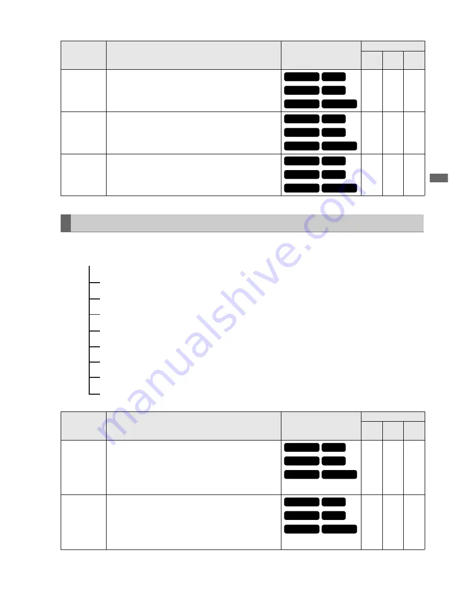
Use this menu to format P2 cards, delete and copy clips and other operations. 

MARKED

CLIPS

Displays thumbnails only for clips to which shot marks have been 

attached. 

M

M

TEXT MEMO

CLIPS

Displays thumbnails only for clips with text memo data. 

M

M

SLOT CLIPS

Displays only clips in selected slots as thumbnails.

M

OPERATION

Item

Settings and brief function description

SYSTEM FREQ 

indications

Mode

2D

(Main)

3D

SYNC

PB

DELETE

Deletes selected clips.

NOTE:

• To interrupt deleting, press the SET button or the CANCEL 

(SHIFT + EXIT) button to cancel the operation. Clips being 

deleted will not be restored even though you interrupted 

deleting.

M

M

FORMAT

Formats P2 cards in the slot selected in the FORMAT menu. 

NOTE:

• Check that no important data remains on a card before 

formatting since data erased by formatting cannot be 

recovered.

• Formats all cards inserted in the slots in 3D REC/PB mode. 

M

M

Item

Settings and brief function description

SYSTEM FREQ 

indications

Mode

2D

(Main)

3D

SYNC

PB

59.94 Hz

50 Hz

23.98 Hz

24 Hz

59-23 Hz

60-24 Hz

59.94 Hz

50 Hz

23.98 Hz

24 Hz

59-23 Hz

60-24 Hz

59.94 Hz

50 Hz

23.98 Hz

24 Hz

59-23 Hz

60-24 Hz

THUMBNAIL

OPERATION

PROPERTY

META DATA

S

TORAGE

S

ETUP

FILE

S

Y

S

TEM INFO

MENU

59.94 Hz

50 Hz

23.98 Hz

24 Hz

59-23 Hz

60-24 Hz

59.94 Hz

50 Hz

23.98 Hz

24 Hz

59-23 Hz

60-24 Hz

Summary of Contents for AG-HDP24E

Page 1: ... see page 90 M0711TO0 PS Volume Note that Operation Instructions Vol 2 describes advanced operations of the Memory Card Portable Recorder For instructions on basic operations of the Memory Card Portable Recorder refer to Operating Instructions Vol 1 printed documents supplied with the unit 2 Before operating this product please read the instructions carefully and save this manual for future use ...

Page 2: ...Note concerning screenshots in these instructions Screenshots from the AG HPD24P are used in these operating instructions Page references In this manual references to pages are indicated as page 00 Terminology The term SD memory card is used below as a generic term for both SD and SDHC memory cards A memory card with the P2 logo for example the separately sold AJ P2E064XG is referred to as a P2 ca...

Page 3: ...onnecting Clips 38 Viewing and Revising Clip Information 39 Thumbnail Editing 39 Attaching Meta data to Clips During Recording 39 Formatting P2 Cards 39 Checking Card Status 39 Synchronous Playback Mode SYNC PB 41 Playback 41 Displaying and Managing Clips 43 Changing Thumbnail Display 43 Playing Back Clips 43 Playing Back at Variable Speed 43 Viewing and Repairing Clip Information 43 Checking Card...

Page 4: ...rouble Free Operation 82 Maintenance 82 Condensation 82 Storage Precautions 82 Warning and Error Messages 83 Error Information 83 Detailed Warning and Error Information 84 Error Information 89 Updating the Firmware in This Unit 90 Handling P2 Card Recording 91 Use of SD SDHC Memory Cards 92 Index 93 ...

Page 5: ...data and enables recording and playback Playback screen Displays video time code remaining battery life and other data and enables playback Thumbnail screen Displays clip thumbnails and properties and manages and plays back clips MODE MODE SET PLAY STILL STOP PLAY STILL STOP PLAY STILL STOP THUMBNAIL THUMBNAIL THUMBNAIL Mode menu Main mode Recording and playback on one unit Recording playback scre...

Page 6: ...the STOP button to stop recording Adjusting the recording volume The level meters show CH1 and CH2 recording volume when you press the REC VOLUME button assigned to a USER button while the menu setting SETUP AUDIO INPUT SEL is set to analog audio input Use the Up Down cursor buttons to select CH1 or CH2 level display Use the Left Right cursor buttons to adjust the level Use the RESET button to res...

Page 7: ...ormat When loop recording is stopped right after deleting old data the time that remains on the card may be shorter than indicated Shot marks cannot be added or deleted during loop recording Text memos cannot be added during loop recording LOOP REC is not available during VFR Variable Frame Rate recording Terminating Loop Recording Mode Use one of the following two methods Hold down the POWER butt...

Page 8: ...ress the Left Right cursor buttons during playback or STILL Playback changes to high speed or slow and indicated as SHTL speed 2 Press the Left Right cursor buttons to change playback speed The playback speed changes each time the buttons are pressed Maximum playback speed depends on the value set by the SETUP BASIC SHUTTLE MAX menu setting Setting Menu BASIC SHUTTLE MAX page 60 Audio is not playe...

Page 9: ...of a playable clip During repeat playback REPEAT appears in the OSD s operating status display Clip and text forward rewind Repeat playback SHTL SHTL 2 0 SHTL 1 0 PLAY SHTL 0 5 SHTL 0 SHTL SHTL 0 0 Right Left Right Right Left Left Right Left Right Left Right Left Right Left Right Left Right Left Up Down NEXT PREV Overview of all clip playback transitions This unit allows you to vary audio and vide...

Page 10: ...n 3 System format Indicates the recording format of the clip at the cursor position 4 Duration Indicates the length duration of the clip at the cursor location and the rough location of current playback The playback location is indicated when the SETUP THUMBNAIL PB POSITION RESUME menu setting is selected Setup Menu THUMBNAIL PB POSITION page 57 When the playback start position is not the beginnin...

Page 11: ... that became defective because the power was shut down during recording or was damaged for some other reason Clips with the yellow bad clip indicator can sometimes be repaired Repairing bad clips page 19 Clips with the red clip indicator cannot be repaired and should be deleted If deleting is not possible format the P2 card Instead of appears to indicate that a clip is not in the P2 standard forma...

Page 12: ...ove efficiency Example Set the SETUP THUMBNAIL menu setting as shown below Set INDICATOR to ALL HIDE Set DATA DISPLAY to CLIP NAME Set THUMBNAIL SIZE to LARGE Set the THUMBNAIL menu setting to SELECTED CLIPS Figure showing thumbnail screen example 1 Press the MENU button 2 Use the Up Down Left Right cursor buttons to set the SETUP DISPLAY OSD OUTPUT menu setting to select output LCD VIDEO OUT or S...

Page 13: ... DATA DISPLAY menu setting and select the items you need Select the items you need and change settings as required Setup Menu THUMBNAIL DATA DISPLAY page 56 4 Press the SET button 5 Press the MENU button to end processing Use the steps below to change the order of year month and day in date indications 1 Open the thumbnail screen 2 Press the MENU button 3 Use the Up Down Left Right cursor buttons ...

Page 14: ...lip the cursor is on After the clip at the cursor location has been played subsequent clips are played back in order When the last clip has been played the thumbnail screen appears NOTE There is no need to select a clip that is when the thumbnail appears inside a blue frame to play it back You can change the thumbnail display settings to play back clips only from selected slots or play back only c...

Page 15: ... clip playback Single clip playback starts from the position specified on the PB POSITION menu setting When JOG VAR SHTL is used to display a still image during playback from the thumbnail screen the USER button to which ONE CLIP PLAY has been assigned allows you to play the entire clip to its end from the still image Setup Menu USER BUTTON page 70 These functions operate in the same manner as in ...

Page 16: ...p NOTE Press the TOP BOTTOM button to move the cursor to the first or last clip 2 Press the SET button A blue frame appears on the clip selected with the cursor to indicate that it is selected NOTE Repeat steps 1 and 2 to select multiple clips After selecting a clip move the cursor to another clip hold down the SHIFT button and press the SET button to select another clip This method allows you to ...

Page 17: ...not a malfunction During LOOP REC or during recording when the SETUP BASIC VFR REC menu setting is ON text memo recording is not available Changing the thumbnail screen to the text memo display allows you to delete text memos 1 Change the thumbnail screen to the text memo display 2 Use the Up Down Left Right cursor buttons to move the cursor to the thumbnail you want to delete and press the SET bu...

Page 18: ... the thumbnail by pressing the USER button instead of making a menu selection 5 Select YES in the confirmation message that appears and press the SET button This starts copying NOTE To interrupt copying press the SET or the CANCEL button to cancel the operation The incomplete copy at the destination is deleted OVERWRITE appears when an attempt is made to place a copy having the same GLOBAL CLIP ID...

Page 19: ...clip NOTE Some clips are so badly damaged they cannot be repaired Such clips are indicated by a red A clip spanning multiple P2 cards that cannot be recognized as a complete clip is marked by the incomplete clip indicator The reconnection function allows you to reconnect related clips and restore the original clip NOTE Incomplete clips occur under the following conditions When the individual clip ...

Page 20: ...erty mode This unit cannot record and play back voice memos 4 Clip information The following information appears 5 Clip meta data This area shows more detailed information on a clip 5 Browse the clip meta data as necessary Use the Up Down Left Right cursor buttons to select a meta data item and press the SET button to view information similar to that shown below Viewing and Revising Clip Informati...

Page 21: ... cannot be revised Insert the P2 card s with the remainder of the clip MEMO of meta data item to which a 100 character or larger memo has been attached cannot be revised 5 Press the EXIT button to end processing ACCESS The date of the last update and other information CREATOR CREATION DATE LAST UPDATE DATE LAST UPDATE PERSON DEVICE Manufacturer serial number and model name of recording equipment S...

Page 22: ...ETUP SYSTEM FREQUENCY menu setting is displayed the icon may appear at the text memo location in the lower half of the monitor instead of the thumbnail that should normally appear A meta data upload file containing the name of the person who shot the video the reporter the shooting location or a text memo and other information can be saved to an SD memory card This data file can be loaded and reco...

Page 23: ...ter value of the USER CLIP NAME for clips exceeding 4 GB In the following case one shot is recorded as multiple clips and the counter value is automatically incremented and recorded for each shot When an 8 GB or larger P2 card is used in this unit and each continuous recording exceeds a specified time Dividing clips over 4 GB in length Vol 1 page 30 When one recording spans multiple cards A P2 dev...

Page 24: ... press the SET button 6 Select YES in the confirmation message that appears and press the SET button The file is now loaded 7 Press the MENU button to end processing Checking and revising loaded meta data Use the following steps to check meta data loaded from an SD memory card 1 Open the thumbnail screen 2 Press the MENU button and choose the META DATA PROPERTY menu setting A screen like the one s...

Page 25: ...f the slot containing the P2 card you want to format and press the SET button NOTE Selecting SD CARD will format an SD memory card inserted in the SD memory card slot 4 Select YES in the confirmation message that appears and press the SET button Card formatting starts NOTE To cancel formatting select NO and press the SET button Check that no important data remains on a device before formatting sin...

Page 26: ...Y PROPERTY SETUP P2CARD CAP menu setting to switch between remaining free space and used space Setup Menu PROPERTY PROPERTY SETUP P2 CARD CAP page 53 1 Write protect mark A write protected P2 card is indicated by the mark displayed here 2 P2 card status The remaining free memory on the P2 card is displayed here in the form of a bar meter and a percentage value Memory used on the P2 card is also di...

Page 27: ...log 6 Card warning messages This warning appears when the following P2 cards are inserted Open Detailed P2 Card Status for more information on this warning RUN DOWN CARD The maximum number of overwrites has been exceeded DIR ENTRY NG The P2 card directory structure is not supported 4 Press the EXIT button to end processing NOTE If the number of clips recorded on a P2 card exceeds the limit OVER MA...

Page 28: ...es cannot be formatted NOTE Use storage devices under the following conditions Use storage devices within their operating specifications temperature etc Do not install storage devices in locations that are unstable or exposed to vibration Some storage devices and cables may not operate normally Use a storage device with sufficient space for copying Storage device types and available functions Stor...

Page 29: ...cording or playback may not occur normally if you do On some storage devices performance of the initial playback confirmation after connecting a hard disk may drop 1 Connect a storage device to the USB 3 0 connector on the front panel 2 Set the STORAGE USB HOST ENABLE menu setting NOTE When set to ENABLE recording and EE output is not available Use cables that conform to the USB 3 0 standard when ...

Page 30: ...s to choose the STORAGE EXPORT menu setting and press the SET button 6 Select the number of the source P2 card slot and press the SET button When the hard disk is in the TYPE S format selecting ALL SLOT will result in a batch export of all inserted cards 7 Select YES in the confirmation message that appears and press the SET button The data will now be exported A progress bar appears during export...

Page 31: ...the copied clip in the storage device folder or partition list that appears and press the SET button NOTE A storage device in the FAT format will display the following folders Root folder Up to three levels of folders containing CONTENTS folder Copying is not possible on a TYPE S storage device without a single partition To enable copying format using a FAT format or use EXPORT to create a partiti...

Page 32: ...in the selected partition or folder as thumbnails Thumbnail Screen Display Vol 1 page 34 Use the following steps to select up to six partitions or folders to use in this way 1 Select a partition or folder in the EXPLORE screen 2 Hold down the SET button 1 sec or longer to complete the operation A check mark appears on next to the selected partition or folder Storage device that makes it possible t...

Page 33: ...t Right cursor buttons to select the OPERATION CHANGE PARTITION NAME menu setting and press the SET button The soft keyboard appears 4 Enter a name for the partition and select OK The name is assigned to the partition Deleting the last partition Choose the OPERATION DELETE LAST PARTITION menu setting Setup Menu OPERATION DELETE LAST PARTITION page 52 to delete the last partition on a storage devic...

Page 34: ...lete on the thumbnail screen on a storage device 2 Press the MENU button 3 Use the Up Down Left Right cursor buttons to choose the OPERATION DELETE menu setting and press the SET button 4 Select YES in the confirmation message that appears and press the SET button NOTE It may not be possible to delete clips with the bad clip indicator and unknown clip indicator SERIAL P2 card serial number MODEL P...

Page 35: ... or other button to close the warning Importing Data by Partition from a TYPE S storage device and P2 Store Use the steps below to import write back data from a storage device to a P2 card data by partition by P2 card to a P2 card that has the same model number as the source card 1 Insert the P2 card that will store the imported partition Be sure to insert a formatted P2 card 2 Connect a storage d...

Page 36: ...og and press the SET button USB DEVICE flashes on the LCD monitor to indicate that the unit is entering the USB host mode After the mode switch USB DEVICE DISCONNECT appears on the LCD monitor This message is replaced by a USB DEVICE CONNECT message when the connection with the PC is completed NOTE Selecting 3D REC PB or SYNC PB mode disables mode changes until communications with the slave device...

Page 37: ... regular P2 clips and care is required to avoid formatting such cards 1 3D Logo Indicates that a 3D thumbnail is displayed 2 Slot status indication L indicates the P2 card status on master side and R indicates that on slave side For details on displayed data see Thumbnail Screen page 10 3 Battery status indicator Indicates remaining battery capacity on the master unit NOTE Battery capacity on the ...

Page 38: ...setting is set to OFF the master side outputs video only via the SDI HDMI outputs Side by side frame packing system Only video from the L side is output to the LCD and SDI HDMI video on the R side is identical to L side video NOTE Clip seek is not performed during playback Use seek from STILL SHTL 0 0 status When the stop state is controlled by an external device depending on the control system vi...

Page 39: ...ursor buttons to choose the OPERATION FORMAT ALL P2 menu setting and press the SET button NOTE Selecting SD CARD will format an SD memory card inserted in the SD memory card slot on the master side 4 Select YES and press the SET button Formatting of all cards starts NOTE To cancel formatting select NO and press the SET button Check that no important data remains on a card before formatting since d...

Page 40: ... or used space Indicates the remaining capacity available for 3D recording or used space and space available for 3D recording NOTE The total of minimum card capacity for the master and slave side slots is total capacity while the total of minimum recording capacity is total remaining recording capacity ...

Page 41: ...lip on the master side and slave side has the same number arranged in the same date created order Time code in the clip is continuous The clips on the master side and slave side have the same length and the initial time code value is the same Correct playback is not possible unless these conditions apply Example 1 The starting point of the clip 1 is the same but their length differs the slave side...

Page 42: ...en the slave Clip 1 playback ends SDI is muted and turns black At this time you can use the SETUP VIDEO DISCRETE BLACK menu setting to select black playback The following figure shows when the DISCRETE BLACK menu setting is OFF HDMI output does not turn black but shows master side L video for both L and R sides NOTE When playback starts from different master and slave frames time code only master ...

Page 43: ...ween clips may occur when playing back clips with different video formats 1080i and 720p or different compression formats DVCPRO HD DVCPRO50 DVCPRO DV AVC Intra 50 and AVC Intra 100 The master side enables variable playback like main mode It does not function on the slave side NOTE Independent right and left systems Video is shown only on the LCD and no output is made to SDI However when the SETUP...

Page 44: ...ing time and total card capacity is displayed in minutes NOTE 600 minutes and longer time periods are displayed in hours with an h appended after the number When remaining time and card length information is not defined the time indication is blank Time exceeding 99 hours is indicated as 99 h 3 Operating status display Indicates current deck status 4 Clip no Indicates the clip number of displayed ...

Page 45: ...when synchronization with the reference signal is not possible This parameter also appears when the SETUP DISPLAY OSD GRADE menu setting is set to MODE TC Also when the SETUP DISPLAY OSD TC SELECT menu setting is set to something other than T S M messages notifying TEXT MEMO and MARKER attachment are output these messages are provided temporary priority also when the REMOTE icon is on NOTE The uni...

Page 46: ...g and Error Information page 84 3 Press the DIAG button The original display reappears You can also press the EXIT button or the MENU button to return to the original display This function displays a simple waveform monitor on the screen for monitoring video Choose the SETUP DISPLAY WFM TYPE menu setting to open the function WAVE Waveform display VECTOR Vectorscope display NOTE Use the SETUP DISPL...

Page 47: ... 59 23 or 60 24 the playback screen and CTL may differ by one frame Time code and other settings Setup Menu TC UB CTL page 62 1 Engage the stop mode Press the STOP button to engage stop mode 2 Use the COUNTER button to select TC or UB 3 Use the SETUP TC UB CTL RUN MODE menu setting to set the run mode of the time code generator 4 Use the SETUP TC UB CTL TCG MODE UBG MODE menu setting to set TC and...

Page 48: ...G MODE to EXT when input of external time code set by the SETUP TC UB CTL EXT TC SEL menu setting was removed from the rear panel connector When menu SETUP SYSTEM FREQUENCY is modified run data is cleared When menu SETUP BASIC VFR REC is set to ON RUN MODE is set to REC RUN regardless of menu setting 1 Press the STOP button to stop recording 2 Use the COUNTER button to select TC 3 Use the SETUP TC...

Page 49: ... UB 3 Press the PLAY button Playback starts and the time code appears on the LCD display Reproducing the Time Code and User Bits 1 3 2 When the time code signal cannot be read an asterisk is displayed The colon between the seconds and the frames changes to a period in drop frame mode Field 1 field 3 Field 2 field 4 ...

Page 50: ... the same format as the system format and for which the same audio bit rate has been set in the menu AUDIO SMPL RES NOTE When the SETUP SYSTEM FREQUENCY is 23 98 Hz 24 Hz 59 23 or 60 24 only clips in a format that can be recorded are displayed Clips without an audio recording are identified by the value that has been set in the menu AUDIO SMPL RES M M SELECTED CLIPS Displays thumbnails only for cl...

Page 51: ... cancel the operation Clips being deleted will not be restored even though you interrupted deleting M M FORMAT Formats P2 cards in the slot selected in the FORMAT menu NOTE Check that no important data remains on a card before formatting since data erased by formatting cannot be recovered Formats all cards inserted in the slots in 3D REC PB mode M M Item Settings and brief function description SYS...

Page 52: ...e clip segments are reconnected the incomplete clip mark will remain M COPY Copies selected clips to a P2 card in a P2 card slot or to a storage device NOTE Take care not to turn off the power or remove insert a card during copying Otherwise the copied clip may become bad If the copied clip goes bad delete it and make a new copy Reconnect incomplete clips before copying M EXCH THUMB NAIL Replaces ...

Page 53: ...mory card information M M M PROPERTY SETUP P2 CARD CAP Select whether remaining capacity or used capacity should appear in the P2 card information REMAIN Remaining capacity indication USED Used capacity indication M M M FREE CAP OF PARTITION Indicates free space on a partition when a STORAGE thumbnail is displayed M THUMBNAIL OPERATION PROPERTY META DATA STORAGE SETUP FILE SYSTEM INFO MENU 59 94 H...

Page 54: ...s USER CLIP NAME When RECORD is ON TYPE1 Records loaded data settings TYPE2 Records loaded data and counter values When RECORD is OFF TYPE1 Records the same value as GLOBAL CLIP ID TYPE2 Records the same value as CLIP NAME M M INITIALIZE Deletes and initializes all loaded meta data M M PROPERTY Checks and revises loaded meta data M M THUMBNAIL OPERATION PROPERTY META DATA STORAGE SETUP FILE SYSTEM...

Page 55: ...Verifies OFF Does not verify NOTE Enabled only for TYPE S formatted storage devices M USB HOST Select whether or not the unit should operate in USB HOST mode ENABLE Operates in USB HOST mode EE and recording are not available DISABLE Disables operation in USB HOST mode NOTE Turning the power OFF cancels this setting The unit will then start up using the default value DISABLE next time it is powere...

Page 56: ...proxy indicator NOTE Regardless of the above settings the bad clip indicator yellow red unknown clip indicator and incomplete clip indicator are always shown The WIDE indicator is not displayed in 3D REC PB mode and SYNC PB mode M M M DATA DISPLAY Select items to appear in the time display TC Time code UB User bits TIME Time of recording DATE Date of recording DATE TIME Date and time of recording ...

Page 57: ... 3 2 NORMAL Normal thumbnail display 4 3 M M M PB POSITION Set the playback start position for playback on the thumbnail screen RESUME From the position where playback was stopped THUMBNAIL TC From the time code of the thumbnail position START TC From the start time code beginning of the clip M M M SORT Specify the order thumbnails appear OFF In recorded order ON Slot order clips in the same slot ...

Page 58: ...ding frame rate LAST UP DATE Indicates last update LAST UP PERSON Indicates last person who updated the clip MANUFACTURER Indicates the name of the manufacturer SERIAL NO Indicates the serial number MODEL NAME Indicates the name of the model ALTITUDE Indicates altitude LONGITUDE Indicates longitude LATITUDE Indicates latitude THUMBNAIL OFFSET Indicates thumbnail offset 3D CLIP Indicates whether a ...

Page 59: ...he recording stopping signals in the LTC information attached to HD SDI signals TYPE2 Recording and stopping is performed automatically according to the recording stopping signals in the SVITC information attached to HD SDI signals TYPE3 Set when other manufacturer s camera recorders are used OFF No automatic recording stopping NOTE When the thumbnail screen is displayed this setting is disabled a...

Page 60: ...lay playback is suspended when playback reaches the clip that is no longer exists Even if you insert a P2 card during repeat play additional clips are not played back until you once stop repeat play and resume it M M M SHUTTLE MAX Sets the maximum shuttle speed operation X8 8 normal speed X16 16 normal speed X32 32 normal speed X60 60 normal speed X100 100 normal speed M M M FF REW MAX Sets the ma...

Page 61: ... off ON Outputs a beep sound OFF Does not output a beep sound NOTE A beep sound is also output from the ANALOG AUDIO MON output connectors M M M Model Recording format Recording Mark TYPE Remarks AJ HDC27F H 720 p over 60p TYPE1 AJ HDX900 720 59 94p 720 23 98p over 59 94p 720 29 97p over 59 94p 720 50p 720 50p over 50p 1080 59 94i TYPE1 TYPE2 When TYPE1 is used set UB_MODE on the camera to FRAM_RA...

Page 62: ...he VITC signal will be inserted When set to 59 94 Hz LINE 10 LINE 18 LINE 20 When set to 50 Hz LINE 7 LINE 12 LINE 22 NOTE You cannot select the same line as in the VITC POS 1 menu This setting is enabled only during VIDEO and SD SDI output Pressing RESET will not restore the factory defaults VITC signals are not output when 23 98 Hz 24 Hz 59 23 or 60 24 is set in the SETUP SYSTEM FREQUENCY menu s...

Page 63: ... SDI output ON Superimposes LTC OFF Does not superimpose LTC M M M TC OUTPUT REF Switches the phase of time code output from the TIME CODE OUT connector relative to external LTC input when TCG MODE is set to EXT Only in EE mode VOUT Synchronized with output video signal TC IN Synchronized with the external time code input M M Item Settings and brief function description XX indicates factory defaul...

Page 64: ...DE data will be recorded when the SETUP SYSTEM FORMAT menu setting is 480i or 576i WIDE Recorded NORMAL Not recorded M SETUP Selects output method for analog composite signals OFF Does not apply the setup to the output 7 5 Applies 7 5 setup to the output M M M EDH SD Specifies whether or not EDH is superimposed on SDI OUT signals ON Signals are superimposed OFF Signals are not superimposed M OUTPU...

Page 65: ...onverted before output In 3D REC PB mode and SYNC PB mode 480i and 576i cannot be selected During playback of 480i 576i formatted clips in SYNC PB mode and when AUTO is selected SDI output is converted to the format selected with the SYSTEM FORMAT menu setting M M M DOWNCONV MODE Specifies the aspect ratio during down conversion FIT V Side cut mode FIT H Letter box mode FIT HV Squeeze mode M M M U...

Page 66: ...alue GM Turning the power off cancels the GAMMA setting M M M AUDIO Item Settings and brief function description XX indicates factory default settings SYSTEM FREQ indications Mode 2D Main 3D SYNC PB INPUT SEL Selects the audio input signal SDI Selects the SDI connector ANALOG Selects the ANALOG AUDIO IN connector INT SG Selects the internal signal generator NOTE When ANALOG is selected in 3D REC P...

Page 67: ...peakers BEEP sounds are not output either M M M LEVEL METER Switches the channels that are indicated on the audio level meter CH1 4 Indicates the levels for CH1 to CH4 CH5 8 Indicates the levels for CH5 to CH8 M M M DISPLAY Item Settings and brief function description XX indicates factory default settings SYSTEM FREQ indications Mode 2D Main 3D SYNC PB OSD OUTPUT Determines whether the thumbnail s...

Page 68: ...umber is indicated as 16b even for a clip without audio data M M M WFM TYPE Selects waveform and vectorscope display WAVE Waveform display VECTOR Vectorscope display OFF Not displayed M M M CROSS HATCH Selects cross hatch display for SDI or HDMI output 1 6 Displays a 1 wide pattern OFF Not displayed NOTE Not displayed for 480i or 576i output Not displayed in 3D REC PB mode and SYNC PB mode when th...

Page 69: ...trast setting becomes the contrast adjustment value for R G and B M M M R CONTRAST Adjusts the R Red contrast of the LCD monitor 30 0 30 NOTE This setting multiplied by the CONTRAST setting becomes the adjustment value M M M G CONTRAST Adjusts the G Green contrast of the LCD monitor 30 0 30 NOTE This setting multiplied by the CONTRAST setting becomes the adjustment value M M M B CONTRAST Adjusts t...

Page 70: ...a REC VOLUME button M M ONE CLIP PLAY Functions as a ONE CLIP PLAY button M M M SLOT CLIPS Switches thumbnail display between SELECTED CLIPS SLOT1 SLOT2 M M SLOT SEL Changes the P2 card slot used for recording M M DATA DISPLAY Changes MENU SETUP THUMBNAIL DATA DISPLAY settings M M M STOP EE SEL Changes MENU SETUP BASIC STOP EE SEL settings M M OUTPUT REF Changes MENU SETUP BASIC OUTPUT REF setting...

Page 71: ...Main 3D SYNC PB SYSTEM Item Settings and brief function description XX indicates factory default settings SYSTEM FREQ indications Mode 2D Main 3D SYNC PB FREQUENCY Selects the system frequency 59 94 Hz Selects 59 94 Hz as the system frequency AG HPD24P default value 50 Hz Selects 50 Hz as the system frequency AG HPD24E default value 23 98Hz Selects 23 98 Hz as the system frequency 24Hz Selects 24 ...

Page 72: ...hen used for recording In 3D REC PB mode DVCPRO HD cannot be selected M M AUDIO SMPL RES Selects quantization bit rate for audio recording in the AVC Intra 100 AVC Intra 50 recording format 16BIT Audio recording bit rate is 16 bits 8 channels are recorded 24BIT Audio recording bit rate is 24 bits 4 channels are recorded NOTE The recording format is 16 bits for DVCPRO HD DVCPRO50 DVCPRO and DV M M ...

Page 73: ...s turned off after 120 minutes of inactivity OFF Does not turn off the unit automatically and allows the power to stay on AG HPD24P default value NOTE Even when set to something other than OFF power is not turned off during playback including variable speed playback fast forward fast rewind and pause and recording When transfers are made to an external device via a USB cable the power is not turne...

Page 74: ...AGE USB HOST SETUP BASIC LOOP REC SETUP BASIC GAMMA SEL Even when ALL is selected in 3D REC PB mode and SYNC PB mode values selected in the SETUP SYSTEM FREQUENCY menu setting are not loaded M M M SAVE AS Saves selected data to an SD memory card after a file name has been entered ALL All the data in the menu W O SYSTEM Items other than SETUP SYSTEM M M M SDCARD PROPERTY Indicates capacity and used...

Page 75: ...O SYSTEM Items other than SETUP SYSTEM NOTE Even when ALL is selected in 3D REC PB mode and SYNC PB mode values selected in the SETUP SYSTEM FREQUENCY menu setting are not initialized M M M Item Settings and brief function description SYSTEM FREQ indications Mode 2D Main 3D SYNC PB 59 94 Hz 50 Hz 23 98 Hz 24 Hz 59 23 Hz 60 24 Hz ...

Page 76: ...tton When ALL is selected to load all items the system will automatically be restarted if SETUP SYSTEM FREQUENCY differs from the current setting 1 Select MENU Insert an SD memory card and select menu item to save from FILE SAVE AS Select ALL all item data or W O SYSTEM data other than menu setting SETUP SYSTEM and press the SET button If the SD memory card has not been formatted use FILE SDCARD F...

Page 77: ... STORAGE SETUP SETUP items excluding SYSTEM menu items SYSTEM INFO Item Settings and brief function description SYSTEM FREQ indications Mode 2D Main 3D SYNC PB VERSION Indicates the version of the firmware M M M MODEL Indicates the model name and serial number M M M HOUR METER Displays the hour meter OPERATION PowerON time POWER ON Power ON count LCD ON LCD on time M M M THUMBNAIL OPERATION PROPER...

Page 78: ...ing format Input signal System frequency SDI output 1 AVC Intra 50 100 1080 59 94i 59 94 1080 59 94i 720 59 94P 480 59 94i 1080 50i 50 1080 50i 720 50P 576 50i 1080 23 98P over 59 94i 2 59 23 1080 23 98PsF 1080 23 98PsF 23 98 1080 23 98PsF 1080 24PsF 24 1080 24PsF 720 59 94P 59 94 720 59 94P 1080 59 94i 480 59 94i 720 50P 50 720 50P 1080 50i 576 50i 720 23 98P over 59 94P 3 59 23 1080 23 98PsF 720...

Page 79: ... 29 97PsF 59 94 1080 29 97PsF 720 59 94P 1 480 59 94i 1 1080 23 98P over 59 94i 5 59 94 1080 23 98PsF 3 1080 59 94i 2 720 59 94P 2 480 59 94i 2 1080 23 98PsF 1080 24PsF 1080 25PsF 720 59 94P 59 94 720 59 94P 1080 59 94i 480 59 94i 720 50P 50 720 50P 1080 50i 576 50i 720 23 98P over 59 94P 7 59 23 1080 23 98PsF 720 24P over 60P 6 60 24 1080 24PsF DVCPRO50 DVCPRO DV 480 59 94i 59 94 480 59 94i 1080 ...

Page 80: ...SET button Use the Up Down Left Right cursor buttons to move the cursor The keypad keys have the functions listed below Full Keyboard Key Function BS Deletes one character Caps Toggles between upper and lower case OK Saves made entries and closes the on screen keyboard EXIT Cancels made entries and closes the on screen keyboard Moves the cursor to the first character Moves the cursor 1 character s...

Page 81: ...he type of keyboard you want to use 1 Press the MENU button 2 Use the Up Down Left Right cursor buttons to select the SETUP THUMBNAIL menu setting and select KEYBOARD 3 Press the SET button This opens a menu for keyboard setup 4 Move the cursor to the keyboard layout you want and press the SET button NOTE If the keyboard draws more than 100 mA a protective circuit may shut down the machine Keyboar...

Page 82: ...59 F 77 F Recommended relative humidity 40 60 Memory card recorder Wrap the unit in a soft cloth to protect it from dust Do not place it in a location exposed to direct sunlight which could damage the finish and the LCD screen Battery pack Storing the battery pack in a location exposed to excessively high or low temperature will reduce its service life Storing it in a location with oily smoke and ...

Page 83: ...ard removal Blinks 4 time per second Repeated rapidly A P2 card was removed during access and an error occurred in inner memory Turn the unit off Repair any clips on the removed P2 card that are corrupted E 31 2 Recording error Blinks 4 times per second Repeated rapidly Recorded data is corrupted Turn the power off then turn it on again and try again Replace a P2 card that does not enable normal r...

Page 84: ... cannot be recorded for example 100 or more text memos have been recorded Operation continues INT SG Displayed for the first 2 seconds when INT SG is selected in menu SETUP VIDEO INPUT SEL or in menu SETUP AUDIO INPUT SEL and the REC button is pressed to engage EE mode Operation continues NO INPUT Displayed for the first two seconds when the REC button is pressed to enter EE mode and INPUT SEL is ...

Page 85: ... playback clip Appears during EE or recording when frame rate data cannot be detected in the user bits data in an HD SDI input or when the input time code is not continuous Normal recording will not be possible under these conditions Check signal input to the unit Input signals with a matching time code and pull down sequence Appears when menu SETUP SYSTEM FREQUENCY is set to 23 98 Hz 24 Hz 59 23 ...

Page 86: ...AVE WARNING A problem on the slave side prevented operation Check status on the slave side STOP 63 SYNC POSI FAILED Failed to synchronize clip location Check the number and type of clips If the reference signal or input signal is corrupted during playback of a 3D clip it may not be possible to synchronize positions on the clip Press the STOP button to stop check connections and input signals befor...

Page 87: ...card Insert a card with sufficient recording capacity MISSING CLIP All cards that contain the clip must be inserted to allow attachment of shot marks Insert all cards that contain the clip NO CARD No P2 or SD memory card is inserted Insert compatible media NO COPY TO SAME CARD A clip cannot be copied to the card storing the original clip Copy the selected clip to a card that does not contain the o...

Page 88: ...P2 card LACK OF CAPACITY Not enough space left on the storage device Use a new storage device with enough free space or a formatted storage device STORAGE DISCONNECTED The unit has been disconnected from the storage device Reconnect the USB cable to the HOST connector If the device still does not operate normally turn it off and then back on again MISMATCH COMPONENT Copying is not possible since t...

Page 89: ...ect the LINK D SUB cable WAITING FOR CONNECTION The unit is waiting for connection for it takes time to detect the synchronized connection of the two units If the signal cannot be detected in 2 minutes an error is generated Locate the cause of the error before connecting again Error Information Error Description Operation No Message E 30 TURN POWER OFF Displayed when an error occurs in reading and...

Page 90: ...For English http panasonic biz sav pass_e 2 Customers not registered for a P2HD 5 Year Warranty Repair Program Check firmware version of the unit in the PROPERTY SYSTEM INFO in the menu Then access the site listed below to check the most recent firmware information and download any firmware you require Download the update file to the unit by placing it on an SD memory card For details on update pr...

Page 91: ...e P2 Viewer software exclusively designed for managing P2 card data which can be downloaded from our Web site For details on the URL Website URL page 2 Follow the steps below to use general IT tools such as Microsoft Windows Explorer or Apple Finder to transfer the data to a PC Be sure to use P2 Viewer to write data back to a P2 card Process the CONTENTS folder and the LASTCLIP TXT file together D...

Page 92: ...ard is a new standard version 3 0 established by the SD Card Association in 2009 for memory cards with capacities exceeding 32 GB Be sure to use the correct adaptors with mini SD mini SDHC microSD and microSDHC cards Note that this unit will not operate normally when only an adaptor without a card is installed Be sure to use this unit to format cards This unit supports the following SD SDHC memory...

Page 93: ...vel indicator 47 Battery status 45 Battery status indicator 12 37 BEEP 61 BRIGHTNESS 69 C CANCEL button 20 Card 26 Card Status 39 43 53 CC F1 BLANK 64 CC F2 BLANK 64 CC REC 64 CH1 INPUT LEVEL 66 CH2 INPUT LEVEL 66 CHANGE PARTITION NAME 52 Changing slots used for recording 6 Charging 24 Checking and revising 24 Clip Information 34 39 43 Clip meta data 20 21 Clip no 11 20 44 CLIP PROPERTY 53 Clips 3...

Page 94: ... 56 Headroom 56 Hot Swap Recording 7 HOUR METER 77 I ID OF 9P REMOTE 61 Importing 35 Incomplete clip indicator 11 21 Incomplete clips 19 38 INDICATOR 56 Information added to clips 20 Information on operational warnings 84 INITIAL MENU 75 INITIALIZE 54 INPUT SEL 63 66 INT SG 63 Internal mode 47 Internal speaker 56 Items to be displayed as properties 14 K Keyboard 56 58 80 KEYBOARD port 23 L LCD 69 ...

Page 95: ... 52 REPEAT PLAY 60 Repeat playback 9 Reproducing the Time Code and User Bits 49 RESET TC PRESET button 19 Resolution 55 REW button 20 REW PREV button 20 RS 422A I O 56 RUN MODE 63 S SAME FORMAT CLIPS 50 Sampling frequency 54 56 SAVE 76 SAVE AS 74 SD analog composite output 55 SD Mode 30 SD serial digital 55 SD SDHC memory card slot 21 SD SDHC Memory Cards 92 SDCARD FORMAT 74 SDCARD PROPERTY 74 SDI...

Page 96: ... clip indicator 11 UPCONV MODE 65 USB DEVICE 18 USB Device 37 36 USB HOST 37 56 45 55 USB HOST Connector 27 USB HOST port 21 USB Keyboard 81 USB2 0 device port 23 Used space 40 User Bits 36 47 USER BUTTON 70 USER CLIP NAME 23 54 USER1 70 71 USER1 3 4 6buttons 19 USER2 71 USER3 71 USER4 71 USER5 71 USER6 71 Using a Keyboard 80 V Variable Frame Rate VFR Recording 7 Variable speed 15 Variable speed p...

Page 97: ...97 ...

Page 98: ... information about collection and recycling of old products and batteries please contact your local municipality your waste disposal service or the point of sale where you purchased the items Penalties may be applicable for incorrect disposal of this waste in accordance with national legislation For business users in the European Union If you wish to discard electrical and electronic equipment ple...

Reviews: